EP0080939B1 - Schütz mit Selbstschutzmittel gegen die Kontaktrückstosskräfte und dessen Anwendung in einem strombegrenzenden Schutzschalter - Google Patents
Schütz mit Selbstschutzmittel gegen die Kontaktrückstosskräfte und dessen Anwendung in einem strombegrenzenden Schutzschalter Download PDFInfo
- Publication number
- EP0080939B1 EP0080939B1 EP82402146A EP82402146A EP0080939B1 EP 0080939 B1 EP0080939 B1 EP 0080939B1 EP 82402146 A EP82402146 A EP 82402146A EP 82402146 A EP82402146 A EP 82402146A EP 0080939 B1 EP0080939 B1 EP 0080939B1
- Authority
- EP
- European Patent Office
- Prior art keywords
- piece
- contactor
- contact
- magnetic
- electromagnet
- Prior art date
- Legal status (The legal status is an assumption and is not a legal conclusion. Google has not performed a legal analysis and makes no representation as to the accuracy of the status listed.)
- Expired
Links
- 230000005291 magnetic effect Effects 0.000 claims abstract description 40
- 230000000694 effects Effects 0.000 claims description 13
- 239000000696 magnetic material Substances 0.000 claims description 9
- 230000004907 flux Effects 0.000 claims description 3
- 244000182067 Fraxinus ornus Species 0.000 claims 1
- 239000004020 conductor Substances 0.000 description 6
- 230000005520 electrodynamics Effects 0.000 description 4
- 238000005476 soldering Methods 0.000 description 4
- 238000003466 welding Methods 0.000 description 4
- 230000006378 damage Effects 0.000 description 3
- 238000009434 installation Methods 0.000 description 3
- 238000004519 manufacturing process Methods 0.000 description 3
- 230000000295 complement effect Effects 0.000 description 2
- 238000005520 cutting process Methods 0.000 description 2
- 238000000926 separation method Methods 0.000 description 2
- 230000002159 abnormal effect Effects 0.000 description 1
- 238000004873 anchoring Methods 0.000 description 1
- 238000007664 blowing Methods 0.000 description 1
- 238000006243 chemical reaction Methods 0.000 description 1
- 238000001514 detection method Methods 0.000 description 1
- 238000006073 displacement reaction Methods 0.000 description 1
- 230000005294 ferromagnetic effect Effects 0.000 description 1
- 230000009931 harmful effect Effects 0.000 description 1
- 239000011810 insulating material Substances 0.000 description 1
- 238000012423 maintenance Methods 0.000 description 1
- 238000012544 monitoring process Methods 0.000 description 1
- 238000013021 overheating Methods 0.000 description 1
- 239000008188 pellet Substances 0.000 description 1
- 238000003825 pressing Methods 0.000 description 1
- 229920006395 saturated elastomer Polymers 0.000 description 1
- 230000006641 stabilisation Effects 0.000 description 1
- 238000011105 stabilization Methods 0.000 description 1
Images


Classifications
-
- H—ELECTRICITY
- H01—ELECTRIC ELEMENTS
- H01H—ELECTRIC SWITCHES; RELAYS; SELECTORS; EMERGENCY PROTECTIVE DEVICES
- H01H77/00—Protective overload circuit-breaking switches operated by excess current and requiring separate action for resetting
- H01H77/02—Protective overload circuit-breaking switches operated by excess current and requiring separate action for resetting in which the excess current itself provides the energy for opening the contacts, and having a separate reset mechanism
- H01H77/10—Protective overload circuit-breaking switches operated by excess current and requiring separate action for resetting in which the excess current itself provides the energy for opening the contacts, and having a separate reset mechanism with electrodynamic opening
- H01H77/101—Protective overload circuit-breaking switches operated by excess current and requiring separate action for resetting in which the excess current itself provides the energy for opening the contacts, and having a separate reset mechanism with electrodynamic opening with increasing of contact pressure by electrodynamic forces before opening
Definitions
- the invention relates to the protection of contactors against the effects of contact separation due to repulsion forces between them.
- a contactor is normally provided to support effective currents of the order of 12 In (or 6 In, depending on the ratings), In being the nominal current. Beyond this value, there is a risk of soldering and, at least, of contact wear, caused by various effects which will be analyzed below.
- Overloading can occur either when the contactor is closed or during its closing. If it corresponds to currents which would exceed, in the absence of rapid protection means, for example 100 ln, the action of the switch member is very rapid, that is to say that the current which flows in the main contactor of the contactor reaches for example 40 to 50 In peak, then drops back to the value 0, in a time, of the order of 2 ms for example, much less than the duration of a half-cycle of the sector.
- the switch member does not exert any action of significant limitation of the current during half-wave and, consequently, a current greater than 6 ln or 12 In can pass through the contactor.
- the repulsive forces then manifest themselves in the vicinity of the crest of the current and, as they are much weaker than in the previous case, when they cease, the contact closes again on a still large current. This results in a significant risk of welding.
- the invention proposes to compensate, during the time interval separating the appearance of the overload and the opening of the circuit, the effect of the repulsive forces of electro-dynamic nature which arise between the fixed and mobile contacts d '' a contactor, in order to prevent the contacts from being able to separate inadvertently with the consequences which would ensue (wear, risk of welding) for certain values of the overload current.
- a contactor comprising, in a known manner, in particular by patents US-A-3123691 and FR-A-1 514069, a control electromagnet having a movable part, a contact assembly comprising at least a first part conductive support of at least one movable contact and at least a second piece conductive support of at least one fixed contact, connecting members between the movable part of the electromagnet and the first piece of movable contact support , an elastic member arranged to cooperate with said first movable contact support part in a direction which establishes a certain contact pressure, and means for locally concentrating the flux created by the flow of current in said conductive parts in the vicinity of said first conductive part, to exert on it a force of attraction which tends to cause the closure of the contacts.
- this contactor is more particularly characterized in that said means comprise at least one first soft magnetic part rigidly coupled to a contact carrier integral with said movable part of the electromagnet and arranged so that, as soon as appears an overload current reaching the intensity that the standards require of a traditional contactor, that is to say six to fifteen times the nominal current, in said first conductive part said first magnetic part exerts a force of attraction on a part of said first conductive part and / or on a second piece of soft magnetic material integral with said first conductive piece or in direct support on said first conductive piece and subjected to the action of a contact pressure spring, said anchoring force being sufficient to counteract the effect of the repulsive forces which are then exerted between the fixed and mobile contacts, while the tensile force developed between the fixed part and the mobile part of the electromagnet is expected to be sufficient, on the one hand, to withstand the additional tensile force exerted on its movable part when said attraction force is exerted, without detachment of said mov
- the compensation device does not contribute in a appreciable manner to modifying the contact pressure, which it only effectively reinforces when an overload develops forces. of notable repulsion.
- the contact pressure is therefore provided, in the traditional way, by a pressure spring associated with the support of the movable contacts of the contactor.
- said first magnetic part has the shape of a U the base of which is rigidly coupled to a contact carrier secured to the movable part of the electromagnet, while the second magnetic part is arranged to form a variable air gap with the upper ends of the branches of the U and that said part of the support conductor of the movable contacts has the form of a blade on which said second part is supported and engaging in the opening of the U by forming a narrow gap.
- the magnetic part indirectly coupled to the mobile part of the electromagnet has the shape of a U and said part of the conductive support of the mobile contacts has the shape of a blade which engages in the opening of the U by forming a narrow air gap.
- said second magnetic piece is held in abutment, by said contact pressure spring associated with the conductive support of the movable contacts, on said part of said support and forms a variable air gap with said first magnetic piece.
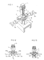
- FIGs 1 to 5 there is shown a contact holder comprising an insulating part or contact holder 1 secured to the armature of an electromagnet, not shown, and two fixed contacts 20a-20b carried by conductors folded in "J" 2a-2b cooperating with a movable contact bridge 3 with two branches 3a-3b respectively carrying contact pads 30a-30b, on either side of a vertical blade 3c.
- a contact pressure spring 4 is housed in a blade of non-magnetic material folded into a U, the lower part of which is arranged so that it can slide inside the part 1, and the upper part of which leaves the part. 1, is provided in the vicinity of its ends with two windows 50-51.
- a U-shaped piece of soft magnetic material 6 is placed between the branches of the blade 5, in their upper part, and fixed at its base to the piece 1 by means of a pin 7.
- the central vertical blade 3c which connects the two branches 3a -3b of the bridge 3 engages in the central groove 60 which is provided with the upper face of the part 6 and, as shown in FIGS. 2 and 3, when the contacts are open , the blade 3c, in edge support at the bottom of the groove 60, has its upper part which protrudes slightly from the groove, so that a second parallelepeledepiece 8, made of soft magnetic material, engaged by the projections 80- 81 with which its edges are provided, in the windows 50-51 and on the lower face of which the blade 3c is pressed, leaves a small gap between said lower face and the upper face of the part 6.
- the spring 4 is pressed, at one end, against the underside of the part 6 and, at its other end, against the base of the part 5.
- the part 1 When, the armature being attracted, the part 1 is driven downwards (arrow F, FIG. 2), the part 6, secured to the part 1 by the pin 7, moves the same distance a.
- the spring 4, by pressing the bottom of the blade 5, drives the latter down over a smaller distance b, which corresponds to the distance between the pellets 20a and 30a on the one hand, 20b and 30b on the other hand .
- the blade 5 drives the part 8 and the bridge 3, until the contacts are closed. At this time, the blade 5 can no longer move and, the part 6 continuing to descend, the spring 4 is compressed, thus ensuring a certain contact pressure and sufficient for nominal operation.
- the arrangement and dimensioning is such that, for current intensities of the order of the nominal value ln, the vector sum of the attractive forces, and of the opposite electro-dynamic forces developed in the conductors folded in "J" , is practically negligible and the contact pressure is only ensured by the spring.
- a contactor made with the figured device has an exceptionally large breaking and closing capacity, of the order of 40 to 50 ln, that is to say several times greater than that which would be obtained with the sole contact pressure spring.
- the breaking or closing capacity may reach, in the described embodiment, which is particularly suitable for the production of large-caliber contactors, effective values of 10 KA to 15 KA instead of 4 KA for a device with a nominal rating of 300 A.
- This makes it possible to envisage using such a contactor without associating it with a limiter or a fuse when the properties of the installation which it supplies make it possible to be certain that the short-circuit intensities -circuit will not exceed these values.
- current monitoring means for example magneto-thermal
- the part 6 will exert, for a closure on a peak current corresponding to an overload, a reaction on the armature in the form of a tensile force tending to tear the armature from the electromagnet. It is therefore important that measures are taken to prevent the armature from becoming detached from the fixed yoke of the electromagnet. To this end, it is advantageous to supply the electromagnet with rectified current during the holding period: the attraction force then never passing through the zero value, the risk of the armature tearing off is reduced. This measure may or may not be combined with a relatively large dimensioning of the electromagnet.
- the additional holding force also has the effect of reducing the phenomenon of mechanical rebound of the contacts which manifests itself during closing, and therefore of reducing wear, starting from around 8 ln.
- a piece 10 of soft magnetic material provided at its base with a double hooking tongue 101 which engages between two suitably profiled projections 90-91 of the internal wall of the part 9.
- the part 10 has a U-shaped cross section and the double-cut movable contact bridge 11, which carries the two contact pads 110a-110b, has a central blade 110c, which engages in the U as shown in the figure 8.
- the fixed contacts 120a and 120b are carried here by rectilinear blades 12a, 12b.
- the piece 9 is provided, at its upper end, with a hoop 92 to which is fixed, by hooking complementary profiled parts, a piece of insulating material 13 provided with a central stud 130 by which one end of a spring is guided of pressure 14.
- the other end of the spring cooperates with a recess 150 which is provided with an insulating part 15 which is supported, by its ends 151-152, on the two respective branches of the movable contact bridge 11.
- the part 9 When, the movable armature of the electromagnet being attracted, the part 9 is driven downwards (arrow F 1 'in FIG. 7), the parts 10 and 13 undergo the same movement a, and the spring 14 moves the part 15, therefore the contact bridge 11, of the distance b 1 ⁇ a, which causes the movable contacts to come to bear on the fixed contacts.
- the part 9 continuing its downward movement over a distance a i -b i , while the blade 110c is immobilized, it ceases to be in contact with the bottom of the U ( Figures 9 and 10) and the spring 14 is compressed to ensure contact pressure.
- This force plays the same role as the attractive force due to the magnetic pieces 6-8 in the embodiment of Figures 1 to 5. It is however less important. To give it a usable value, we will advantageously reduce the air gap between the branches of the U precisely, by giving this central part the shape of a blade placed on edge in a narrow groove of the U.
- the fixed contacts 12a-120a, 12b-120b are rectilinear as in that of Figures 6 to 10 and the insulating part 9, integral with the armature of the electromagnet, cooperates at its upper part with an insulating part 13 identical to that of FIGS. 6 to 10 and also serving to guide and support one end of the spring 14.
- the latter bears, at its other end, on an insulating part 16 which itself supports, by its central triangular projecting part 160, on a first blade 17 of soft magnetic material, which in turn presses on a movable contact blade 18, provided with contacts 180a-180b.
- a second blade 19 made of soft magnetic material is fixed, for example by means of a bolt 190, to the lower part of the part 9.
- the part 19 separates from the parts 17-18 and, the part 13 undergoing the same displacement, greater than the distance between the contacts , the spring 14 which pressed the part 18 on the part 19 until the establishment of the contacts, is then compressed by an additional quantity to ensure the contact pressure.
- the device could be applied to seedlings single contact breakers.
- the shape and arrangement of the magnetic piece or pieces could be subject to variants, as well as those of the contact assembly itself.
- the active air gaps are defined by the slot of the U.
- parts corresponding to those referenced by 17, 18, 19 could have flat or rectilinear shapes, means not described, but obvious to those skilled in the art, moreover making it possible to ensure lateral support of the contact bridge and of the ferromagnetic parts.
- Such an arrangement is therefore particularly advantageous due to the fact that it is much easier to manufacture a circuit breaker or a limiting stage, which is able to effectively limit the peak currents mentioned above, while it is very difficult to limit the peak currents of the order of 15 to 20 ln for which the faults of traditional contactors appear precisely.
Landscapes
- Physics & Mathematics (AREA)
- Electromagnetism (AREA)
- Breakers (AREA)
- Arc-Extinguishing Devices That Are Switches (AREA)
- Contacts (AREA)
- Emergency Protection Circuit Devices (AREA)
- Professional, Industrial, Or Sporting Protective Garments (AREA)
- Fuses (AREA)
- Coupling Device And Connection With Printed Circuit (AREA)
- Dry Shavers And Clippers (AREA)
- Electric Propulsion And Braking For Vehicles (AREA)
- Axle Suspensions And Sidecars For Cycles (AREA)
Claims (11)
Priority Applications (1)
| Application Number | Priority Date | Filing Date | Title |
|---|---|---|---|
| AT82402146T ATE18959T1 (de) | 1981-11-30 | 1982-11-25 | Schuetz mit selbstschutzmittel gegen die kontaktrueckstosskraefte und dessen anwendung in einem strombegrenzenden schutzschalter. |
Applications Claiming Priority (2)
| Application Number | Priority Date | Filing Date | Title |
|---|---|---|---|
| FR8122957A FR2517463A1 (fr) | 1981-11-30 | 1981-11-30 | Contacteur muni de moyens d'auto-protection contre les effets des forces de repulsion entre les contacts, et son association a un organe de coupure et de limitation des courants de court-circuit |
| FR8122957 | 1981-11-30 |
Publications (3)
| Publication Number | Publication Date |
|---|---|
| EP0080939A1 EP0080939A1 (de) | 1983-06-08 |
| EP0080939B1 true EP0080939B1 (de) | 1986-04-02 |
| EP0080939B2 EP0080939B2 (de) | 1990-06-27 |
Family
ID=9264794
Family Applications (1)
| Application Number | Title | Priority Date | Filing Date |
|---|---|---|---|
| EP82402146A Expired - Lifetime EP0080939B2 (de) | 1981-11-30 | 1982-11-25 | Schütz mit Selbstschutzmittel gegen die Kontaktrückstosskräfte und dessen Anwendung in einem strombegrenzenden Schutzschalter |
Country Status (12)
| Country | Link |
|---|---|
| US (1) | US4513270A (de) |
| EP (1) | EP0080939B2 (de) |
| JP (1) | JPS58103719A (de) |
| AT (1) | ATE18959T1 (de) |
| BR (1) | BR8206904A (de) |
| CA (1) | CA1182156A (de) |
| DE (1) | DE3270302D1 (de) |
| ES (1) | ES8308143A1 (de) |
| FR (1) | FR2517463A1 (de) |
| IE (1) | IE53984B1 (de) |
| IN (1) | IN159760B (de) |
| MX (1) | MX151968A (de) |
Families Citing this family (36)
| Publication number | Priority date | Publication date | Assignee | Title |
|---|---|---|---|---|
| FR2559307B1 (fr) * | 1984-02-03 | 1986-06-13 | Telemecanique Electrique | Contact equipe d'un compensateur magnetique autoliberable a partir d'un seuil de force de compensation, et contacteur-disjoncteur utilisant un tel contact |
| FR2559308B1 (fr) * | 1984-02-03 | 1986-10-17 | Telemecanique Electrique | Contact equipe d'un compensateur magnetique avec seuil de liberation reglable et contacteur-disjoncteur utilisant un tel contact |
| JPS6116841U (ja) * | 1984-06-20 | 1986-01-31 | 三菱電機株式会社 | 可動接触子の保持構造 |
| SE460812B (sv) * | 1988-02-08 | 1989-11-20 | Asea Brown Boveri | Elkopplare |
| DE19602118C2 (de) * | 1996-01-22 | 1999-12-30 | Siemens Ag | Elektrisches Schaltgerät |
| DE19617136C2 (de) * | 1996-04-29 | 2000-05-11 | Siemens Ag | Schaltgerät |
| DE29714318U1 (de) * | 1997-08-11 | 1997-12-04 | Siemens AG, 80333 München | Kontaktsystem für Schaltgeräte |
| DE10011985A1 (de) * | 2000-03-11 | 2001-09-13 | Moeller Gmbh | Kontaktsystem für ein Niederspannungsschaltgerät |
| US6545584B2 (en) * | 2001-01-17 | 2003-04-08 | Eaton Corporation | Circuit breaker with inertia device to prevent shockout |
| FR2829869B1 (fr) * | 2001-09-20 | 2003-10-31 | Schneider Electric Ind Sa | Appareil electrique interrupteur muni d'un dispositif de commutation de contact |
| US6958671B2 (en) * | 2001-11-15 | 2005-10-25 | Square D Company | Electrical contactor with positive temperature coefficient resistivity element |
| DE102006034818B3 (de) * | 2006-07-27 | 2008-01-03 | Moeller Gmbh | Kontaktsystem einer elektrischen Schaltanordnung |
| JP5206157B2 (ja) * | 2008-06-30 | 2013-06-12 | オムロン株式会社 | 電磁継電器 |
| JP5163317B2 (ja) * | 2008-06-30 | 2013-03-13 | オムロン株式会社 | 接点装置 |
| ES2442872T3 (es) | 2008-12-12 | 2014-02-14 | Tyco Electronics Amp Gmbh | Puente de contactos con imanes de soplado |
| JP4807430B2 (ja) * | 2009-03-30 | 2011-11-02 | 富士電機機器制御株式会社 | 電磁接触器 |
| FR2947667A1 (fr) * | 2009-07-01 | 2011-01-07 | Schneider Electric Ind Sas | Asservissement via un dispositif de compensation magnetique des forces de repulsion et contacteur comprenant un tel dispositif |
| JP5521852B2 (ja) * | 2010-03-30 | 2014-06-18 | アンデン株式会社 | 電磁継電器 |
| DE112011106154B4 (de) | 2010-07-16 | 2024-05-02 | Panasonic Intellectual Property Management Co., Ltd. | Kontaktvorrichtung |
| KR101072627B1 (ko) * | 2010-10-15 | 2011-10-13 | 엘에스산전 주식회사 | 전자 개폐기의 가동접점 조립체 |
| DE102012102431B4 (de) * | 2012-03-21 | 2019-11-07 | Te Connectivity Germany Gmbh | Leitungsschutzschalter |
| US20140002215A1 (en) * | 2012-06-29 | 2014-01-02 | Siemens Industry, Inc. | Electrical contact apparatus, assemblies, and methods of operation |
| FR3007888B1 (fr) * | 2013-06-27 | 2015-07-17 | Schneider Electric Ind Sas | Contacteur electrique et procede de commande d'un tel contacteur |
| JP5845467B2 (ja) * | 2014-06-18 | 2016-01-20 | パナソニックIpマネジメント株式会社 | 接点装置 |
| FR3023651B1 (fr) | 2014-07-11 | 2017-10-20 | Schneider Electric Ind Sas | Disjoncteur electrique incluant un organe mecanique de blocage d'un pont mobile |
| KR20200000311A (ko) * | 2018-08-31 | 2020-01-02 | 엘에스산전 주식회사 | 직류 릴레이 |
| KR102324514B1 (ko) * | 2018-08-31 | 2021-11-10 | 엘에스일렉트릭 (주) | 직류 릴레이 |
| KR102725406B1 (ko) * | 2018-11-09 | 2024-11-04 | 샤먼 홍파 일렉트릭 파워 컨트롤즈 컴퍼니 리미티드 | 단락전류 방지용 직류 릴레이 |
| CN110223883B (zh) * | 2019-07-09 | 2025-10-28 | 森萨塔科技(芜湖)有限公司 | 高压直流继电器的推动结构 |
| EP4086931B1 (de) * | 2019-12-31 | 2026-03-11 | Xiamen Hongfa Electric Power Controls Co., Ltd. | Gleichstromrelais für anti-kurzschlussstrom und -lichtbogenlöschung |
| KR102524508B1 (ko) * | 2020-11-04 | 2023-04-21 | 엘에스일렉트릭(주) | 가동 접촉자부 및 이를 포함하는 직류 릴레이 |
| KR102571418B1 (ko) * | 2020-11-04 | 2023-08-28 | 엘에스일렉트릭(주) | 가동 접촉자부 및 이를 포함하는 직류 릴레이 |
| CN112563079B (zh) * | 2020-11-30 | 2024-02-20 | 武汉同力同为科技有限公司 | 一种抗短路能力提升开关装置的动触桥保持结构 |
| CN112542331B (zh) * | 2020-11-30 | 2024-02-23 | 武汉同力同为科技有限公司 | 一种抗短路能力提升开关装置的动触桥保持结构 |
| CN112542355B (zh) * | 2020-11-30 | 2024-02-23 | 武汉同力同为科技有限公司 | 一种抗短路能力提升的直流继电器 |
| US12531199B2 (en) * | 2021-11-05 | 2026-01-20 | Sensata Technologies, Inc. | Component assemblies and methods of manufacturing component assemblies that include a magnetic yoke assembly for electromechanical contactors and relays |
Family Cites Families (8)
| Publication number | Priority date | Publication date | Assignee | Title |
|---|---|---|---|---|
| US3123691A (en) * | 1964-03-03 | Movable contact assembly with a magnetic shield | ||
| BE510633A (de) * | 1951-09-19 | |||
| US2841670A (en) * | 1954-12-23 | 1958-07-01 | Allis Chalmers Mfg Co | Frictionless plunger switch having alignable self-holding contacts |
| US3263042A (en) * | 1963-02-18 | 1966-07-26 | Westinghouse Electric Corp | Electric control device with electromagnetic contact-biasing means |
| FR1514069A (fr) * | 1964-02-18 | 1968-02-23 | Cem Comp Electro Mec | Perfectionnements aux verrous électromagnétiques pour contacts électriques |
| US3887888A (en) * | 1973-04-04 | 1975-06-03 | Arrow Hart Inc | High current switch |
| JPS5529982U (de) * | 1978-08-16 | 1980-02-27 | ||
| FR2483683A1 (fr) * | 1980-05-30 | 1981-12-04 | Telemecanique Electrique | Contacteur ayant des proprietes de disjoncteur |
-
1981
- 1981-11-30 FR FR8122957A patent/FR2517463A1/fr active Granted
-
1982
- 1982-11-22 IE IE2771/82A patent/IE53984B1/en not_active IP Right Cessation
- 1982-11-24 IN IN871/DEL/82A patent/IN159760B/en unknown
- 1982-11-25 EP EP82402146A patent/EP0080939B2/de not_active Expired - Lifetime
- 1982-11-25 AT AT82402146T patent/ATE18959T1/de not_active IP Right Cessation
- 1982-11-25 DE DE8282402146T patent/DE3270302D1/de not_active Expired
- 1982-11-29 BR BR8206904A patent/BR8206904A/pt not_active IP Right Cessation
- 1982-11-29 CA CA000416608A patent/CA1182156A/fr not_active Expired
- 1982-11-30 JP JP57210522A patent/JPS58103719A/ja active Granted
- 1982-11-30 US US06/445,774 patent/US4513270A/en not_active Expired - Lifetime
- 1982-11-30 ES ES517823A patent/ES8308143A1/es not_active Expired
- 1982-11-30 MX MX195395A patent/MX151968A/es unknown
Also Published As
| Publication number | Publication date |
|---|---|
| FR2517463B1 (de) | 1984-11-02 |
| MX151968A (es) | 1985-05-22 |
| DE3270302D1 (en) | 1986-05-07 |
| EP0080939B2 (de) | 1990-06-27 |
| ATE18959T1 (de) | 1986-04-15 |
| ES517823A0 (es) | 1983-08-16 |
| IE822771L (en) | 1983-05-30 |
| JPH0463489B2 (de) | 1992-10-12 |
| JPS58103719A (ja) | 1983-06-20 |
| BR8206904A (pt) | 1983-10-04 |
| CA1182156A (fr) | 1985-02-05 |
| EP0080939A1 (de) | 1983-06-08 |
| US4513270A (en) | 1985-04-23 |
| ES8308143A1 (es) | 1983-08-16 |
| IE53984B1 (en) | 1989-05-10 |
| IN159760B (de) | 1987-06-06 |
| FR2517463A1 (fr) | 1983-06-03 |
Similar Documents
| Publication | Publication Date | Title |
|---|---|---|
| EP0080939B1 (de) | Schütz mit Selbstschutzmittel gegen die Kontaktrückstosskräfte und dessen Anwendung in einem strombegrenzenden Schutzschalter | |
| EP2466601B1 (de) | Unterbrechungsvorrichtung mit Monitor mit Lichtbogenunterbrechung | |
| FR2608312A1 (fr) | Agencement de contacts pour disjoncteur en boitier moule | |
| FR2547454A1 (fr) | Dispositif reajustable de fermeture d'un circuit electrique | |
| FR2493591A1 (fr) | Interrupteur electrique | |
| FR2706072A1 (fr) | Appareil électromécanique interrupteur à commutation d'arc. | |
| FR2844392A1 (fr) | Disjoncteur a deux boitiers | |
| FR2559308A1 (fr) | Contact equipe d'un compensateur magnetique avec seuil de liberation reglable et contacteur-disjoncteur utilisant un tel contact | |
| EP2270829B1 (de) | Steuerung über eine Einrichtung zur magnetischen Kompensation einer Rückstosskraft und Schaltschutz mit einer solchen Vorrichtung | |
| EP1901320A1 (de) | Kontaktvorrichtung für ein Elektrogerät und Elektrogerät mit derartiger Vorrichtung | |
| FR2777111A1 (fr) | Disjoncteur | |
| EP0537090B1 (de) | Elektrischer Schützschalter mit Einfügung von zusätzlichen Windungen im Magnetauslöser | |
| FR2595865A1 (fr) | Interrupteur electrique, plus particulierement son actionneur magnetique de contact a haute vitesse | |
| EP3261105B1 (de) | Elektrisches gerät zum leitungsschutz | |
| EP0118334B2 (de) | Strombegrenzender Schalter | |
| EP0693764B1 (de) | Elektrischer Lastschalter mit elektromagnetischem Betätiger für Hochstrom | |
| JPS5848979B2 (ja) | 回路しや断器 | |
| WO2006045946A1 (fr) | Dispositif de protection contre les surtensions a capacite de deconnexion amelioree | |
| EP0072285B1 (de) | Vorrichtung zum Öffnen von beweglichen Kontakten von Schaltern zum Begrenzen von Kurzschlussströmen | |
| EP0130208A1 (de) | Schalter mit bedientem öffnen und schliessen und mit automatischer öffnung im fall eines überstromes. | |
| EP3349231B1 (de) | Elektromechanisches schütz | |
| EP0657907B1 (de) | Stromunterbrechungsteil eines Schaltgerätes, insbesonders eines Schützes oder eines Schutzschalters | |
| FR2534080A1 (fr) | Appareil de mise a la masse automatique de structures accidentellement sous tension | |
| FR2953979A1 (fr) | Dispositif de coupure avec circuit magnetique de renforcement | |
| FR2953986A1 (fr) | Dispositif de coupure a indicateur de soudure des contacts |
Legal Events
| Date | Code | Title | Description |
|---|---|---|---|
| PUAI | Public reference made under article 153(3) epc to a published international application that has entered the european phase |
Free format text: ORIGINAL CODE: 0009012 |
|
| 17P | Request for examination filed |
Effective date: 19821129 |
|
| AK | Designated contracting states |
Designated state(s): AT CH DE GB IT LI SE |
|
| GRAA | (expected) grant |
Free format text: ORIGINAL CODE: 0009210 |
|
| AK | Designated contracting states |
Kind code of ref document: B1 Designated state(s): AT CH DE GB IT LI SE |
|
| REF | Corresponds to: |
Ref document number: 18959 Country of ref document: AT Date of ref document: 19860415 Kind code of ref document: T |
|
| REF | Corresponds to: |
Ref document number: 3270302 Country of ref document: DE Date of ref document: 19860507 |
|
| ITF | It: translation for a ep patent filed | ||
| PLBI | Opposition filed |
Free format text: ORIGINAL CODE: 0009260 |
|
| 26 | Opposition filed |
Opponent name: SIEMENS AKTIENGESELLSCHAFT, BERLIN UND MUENCHEN Effective date: 19861208 |
|
| PUAH | Patent maintained in amended form |
Free format text: ORIGINAL CODE: 0009272 |
|
| STAA | Information on the status of an ep patent application or granted ep patent |
Free format text: STATUS: PATENT MAINTAINED AS AMENDED |
|
| RAP2 | Party data changed (patent owner data changed or rights of a patent transferred) |
Owner name: TELEMECANIQUE |
|
| 27A | Patent maintained in amended form |
Effective date: 19900627 |
|
| AK | Designated contracting states |
Kind code of ref document: B2 Designated state(s): AT CH DE GB IT LI SE |
|
| ITF | It: translation for a ep patent filed | ||
| REG | Reference to a national code |
Ref country code: CH Ref legal event code: PFA Free format text: TELEMECANIQUE |
|
| ITTA | It: last paid annual fee | ||
| EAL | Se: european patent in force in sweden |
Ref document number: 82402146.3 |
|
| PGFP | Annual fee paid to national office [announced via postgrant information from national office to epo] |
Ref country code: AT Payment date: 19951012 Year of fee payment: 14 |
|
| PGFP | Annual fee paid to national office [announced via postgrant information from national office to epo] |
Ref country code: GB Payment date: 19961119 Year of fee payment: 15 |
|
| PG25 | Lapsed in a contracting state [announced via postgrant information from national office to epo] |
Ref country code: AT Effective date: 19961125 |
|
| PGFP | Annual fee paid to national office [announced via postgrant information from national office to epo] |
Ref country code: CH Payment date: 19961125 Year of fee payment: 15 |
|
| PGFP | Annual fee paid to national office [announced via postgrant information from national office to epo] |
Ref country code: SE Payment date: 19961127 Year of fee payment: 15 |
|
| PGFP | Annual fee paid to national office [announced via postgrant information from national office to epo] |
Ref country code: DE Payment date: 19971108 Year of fee payment: 16 |
|
| PG25 | Lapsed in a contracting state [announced via postgrant information from national office to epo] |
Ref country code: GB Free format text: LAPSE BECAUSE OF NON-PAYMENT OF DUE FEES Effective date: 19971125 |
|
| PG25 | Lapsed in a contracting state [announced via postgrant information from national office to epo] |
Ref country code: SE Free format text: LAPSE BECAUSE OF NON-PAYMENT OF DUE FEES Effective date: 19971126 |
|
| PG25 | Lapsed in a contracting state [announced via postgrant information from national office to epo] |
Ref country code: LI Free format text: LAPSE BECAUSE OF NON-PAYMENT OF DUE FEES Effective date: 19971130 Ref country code: CH Free format text: LAPSE BECAUSE OF NON-PAYMENT OF DUE FEES Effective date: 19971130 |
|
| GBPC | Gb: european patent ceased through non-payment of renewal fee |
Effective date: 19971125 |
|
| REG | Reference to a national code |
Ref country code: CH Ref legal event code: PL |
|
| EUG | Se: european patent has lapsed |
Ref document number: 82402146.3 |
|
| PG25 | Lapsed in a contracting state [announced via postgrant information from national office to epo] |
Ref country code: DE Free format text: LAPSE BECAUSE OF NON-PAYMENT OF DUE FEES Effective date: 19990901 |