EP0081293A1 - Mécanisme d'étanchéité pour têtes de dents dans une pompe ou un moteur à engrenages - Google Patents
Mécanisme d'étanchéité pour têtes de dents dans une pompe ou un moteur à engrenages Download PDFInfo
- Publication number
- EP0081293A1 EP0081293A1 EP19820305755 EP82305755A EP0081293A1 EP 0081293 A1 EP0081293 A1 EP 0081293A1 EP 19820305755 EP19820305755 EP 19820305755 EP 82305755 A EP82305755 A EP 82305755A EP 0081293 A1 EP0081293 A1 EP 0081293A1
- Authority
- EP
- European Patent Office
- Prior art keywords
- gears
- top sealing
- tooth top
- seal block
- tooth
- Prior art date
- Legal status (The legal status is an assumption and is not a legal conclusion. Google has not performed a legal analysis and makes no representation as to the accuracy of the status listed.)
- Withdrawn
Links
Images


Classifications
-
- F—MECHANICAL ENGINEERING; LIGHTING; HEATING; WEAPONS; BLASTING
- F04—POSITIVE - DISPLACEMENT MACHINES FOR LIQUIDS; PUMPS FOR LIQUIDS OR ELASTIC FLUIDS
- F04C—ROTARY-PISTON, OR OSCILLATING-PISTON, POSITIVE-DISPLACEMENT MACHINES FOR LIQUIDS; ROTARY-PISTON, OR OSCILLATING-PISTON, POSITIVE-DISPLACEMENT PUMPS
- F04C15/00—Component parts, details or accessories of machines, pumps or pumping installations, not provided for in groups F04C2/00 - F04C14/00
- F04C15/06—Arrangements for admission or discharge of the working fluid, e.g. constructional features of the inlet or outlet
- F04C15/062—Arrangements for supercharging the working space
-
- F—MECHANICAL ENGINEERING; LIGHTING; HEATING; WEAPONS; BLASTING
- F04—POSITIVE - DISPLACEMENT MACHINES FOR LIQUIDS; PUMPS FOR LIQUIDS OR ELASTIC FLUIDS
- F04C—ROTARY-PISTON, OR OSCILLATING-PISTON, POSITIVE-DISPLACEMENT MACHINES FOR LIQUIDS; ROTARY-PISTON, OR OSCILLATING-PISTON, POSITIVE-DISPLACEMENT PUMPS
- F04C15/00—Component parts, details or accessories of machines, pumps or pumping installations, not provided for in groups F04C2/00 - F04C14/00
- F04C15/0003—Sealing arrangements in rotary-piston machines or pumps
- F04C15/0007—Radial sealings for working fluid
- F04C15/0019—Radial sealing elements specially adapted for intermeshing-engagement type machines or pumps, e.g. gear machines or pumps
Definitions
- the present invention relates to a gear pump or motor with gears engaged with each other with their external teeth.
- a gear pump or motor with a cover and a mounting flange provided on both sides of the housing, k with the shafts protruded on both sides of said two gears and supported by the bearings provided in the cover and the mounting flange, and with a seal block arranged on the higher pressure side of the housing, to seal the tooth tops of said gears on the delivery side.
- a cover and a mounting flange(not illustrated) are provided on both sides of a housing 1, and bushings 2 and 3 (bushings on the cover side are not illustrated) are pressed in the cover and the mounting flange.
- the bushings 2 and 3 support the gear shafts 6 and 7 of gears 4 and 5 and have inward curves of a side plate 8 fitted on their circumferential surfaces.
- the outward curves of said side plate 8 are made to coincide with the inward curves of a seal block 9, to support the seal block 9.
- the seal block 9 supported as mentioned above has a loading area 10 formed on its outwardly curved surface which is a contact surface with the housing 1, allowing a high pressure to be applied to the loading area 10 from high pressure introducing holes 11 and 12.
- the high pressure introduced into the loading area 10 is balanced by the pressure in the spaces of said gears, to seal the tooth tops of the gears by the inwardly curved surfaces of the seal block 9.
- the loading area 10 is determined, to determine the load, but if said pump is operated at a high speed at a high pressure, said equation cannot be set up.
- said conventional pump has a disadvantage that the volumetric efficiency is remarkably lowered by the leak from said clearance S.
- the object of the present invention is to provide a tooth top sealing mechanism for a gear pump or motor which prevents the generation of excessive load and keeps the clearance between the seal block and the tooth tops always in an optimum condition.
- the substantial tooth top sealing length l of the seal block is made approximately equal to, but larger than the adjacent teeth pitch P of said gears, and throttle slots are formed in the positions adjacent to said tooth top sealing portions on the low pressure side.
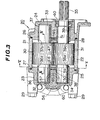
- a gear pump 20 has a housing 21 consisting of a casing 22, a cover 23 and a mounting flange 24.
- Said casing 22 is cylindrical, and closed by the cover 23 on-one side and the mounting flange 24 on the other side.
- the cover 23 and the mounting flange 24 are connected with both the ends of the casing 22 respectively through seal members 25 and 26 by fitting joints 27 and 28, being fastened firmly by bolts 29. In this joining, dowel pins as used in the ordinary gear pump are not required.
- the casing 22 contains a pair of gears 30 and 31 engaged with each other as pumping components.
- the gears 30 and 31 are provided with shafts 32 & 33 and 34 & 35 respectively on both sides.
- These shafts 32 to 35 are supported rotatably by bearings 36 & 37 and 38 & 39 as bushing fitted in the cover 23 and the mounting flange 24.
- These bearings 36 to 39 are protruded at their inner ends to some extent from the cover 23 and the mounting flange 24, to form protrusions 36a, 37a, 38a and 39a.
- the shaft 35 on one side of said gear 30 is protruded' outward through the mounting flange 24, and can be connected with a power source outside the gear pump 10.
- an oil seal 40 is fitted, to seal the clearance between the shaft 35 and the mounting flange 24.
- a seal block 41 is provided between the inside wall of the casing 22 and the tooth tops of the gears 30 and 31.
- the outwardly curved surface of the seal block 41 is formed to suit the inside wall surface of the casing 22, and inwardly curved surfaces are formed inside to suit the outside contours of the gears 30 and 31.
- the seal block 41 On the outwardly curved surface of the seal block 41, there is a high pressure area 43 sectioned by a seal member 42, and the high pressure area 43 communicates to the delivery side of the gears 30 and 31 through a radial high pressure introducing hole 44 and an axial high pressure groove 45 formed in the seal block 41.
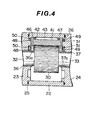
- Said seal block 41 is almost equal to the overall width of the chamber in the casing 22 containing the gears 30 and 31 as can be seen from Fig. 4. Therefore, the seal block 41 is limited in its axial movement by the inside wall surfaces of the cover 23 and the mounting flange 24, but is arranged to be able to move radially to some extent in the range between the inside wall surface of the casing 22 and the tooth tops of the gears 30 and 31.
- the gears 3 0 and 31 are made to be somewhat more narrow than the overall width in said casing 22.
- clearances are formed between the side surfaces of the gears and the cover 23 and the mounting flange 24, by narrowing the width of the gears 30 and 31, and in the clearances, side plates 46 and 47 made of steel are provided.
- the side plate 46- is positioned between the cover 23 and the side surfaces of the gears 30 and 31 facing it, while the side plate 47 is positioned between the mounting flange 24 and the side surfaces of the gears 30 and 31 facing it.
- the side plate 46 consists of a central portion 46a and branching portions 46b and 46c.
- the central portion 46a is positioned between said protrusions 36a and 38a of the bearings 36 and 38, and the branching portions 46b and 46c are formed to suit the circumferences of the protrusions 36a and 38a.
- the inside diameter of the curved surfaces 46e formed by the inward curves of the central portion 46a and the branching portions 46b and 46c exactly fits the protrusions 36a and 38a of the bearings 36 and 38.
- the outwardly curved surfaces of said branching portions 46b and 46c are the same in form as the outside contours of the gears 30 and 31, viz.
- the outwardly curved surfaces of the side plates 46 and 47 keep arcs dimensionally somewhat smaller than the outside contours of the gears 30 and 31, when the curved surfaces 46d, 46e, 47d and 47e of the side plates are supported by the circumferential surfaces of the protrusions 36a to 39a of the bearings 36 to 39.
- pressure areas 50 and 51 are formed in the inside wall portions of the cover 23 and the mounting flange 24 respectively adjacent to the side plates 46 and 47.
- the side plate 46 has speed slots 52 and 53 formed on the outwardly curved surfaces on the high pressure side and throttle slots 54 and 55 formed on the outwardly curved surfaces on the low pressure side.
- the substantial tooth top sealing length in which the seal block 41 and the side plates 46 and 47 seal the tooth tops of the gears is from point A to point B excluding the speed slots and the throttle slots as shown in Fig. 5.
- Said substantial tooth top sealing length 1 is made to be approximately equal to, but larger than the adjacent teeth pitch P of the gears.
- the pressure medium is sucked toward the suction side of the chamber in the casing 22 through an axial passage 57 from an inlet port 56 provided at one side of the cover (see Fig. 3), and is carried toward the delivery side by the gears 30 and 31 rotating mutually in the other directions.
- the pressure medium carried as mentioned above is fed from the high pressure groove 45 formed in the seal block 4l through an axial passage 59 formed in the cover 23 and an outlet port 60 opening toward the other side of the cover 23 (see Fig. 3), to an actuator not illustrated.
- the high pressure generated on the delivery side of the gears 30 and 31 in this way acts from the high pressure groove 45 to the seal block 41 onto the pressure areas 50 and 51 at the rear of the side plates 46 and 47.
- said high pressure acts also on the pressure area 43 at the rear of the seal block 41 through the high pressure introducing hole 44, and the seal block 41, being loaded with the high pressure on the rear side, is pressed against the tooth tops of the gears 30 and 31.
- the seal block 41 is shaved off on the inwardly curved surfaces by the tooth tops of the gears 30 and 31, and the tooth tops of the gears 30 and 31 slightly bite the seal block 41, for good sealing of the tooth tops of the gears 30 and 31.
- the depth of bite by the tooth tops of the gears 30 and 31 into the seal block 41 is as far as the inwardly curved surfaces of the seal block 41 are supported in contact with the outwardly curved surfaces of the side plates 46 and 47.
- the tooth tops of the gears are sealed by the inwardly curved surfaces of the seal block 41 as mentioned above.
- the substantial tooth top sealing length 1 is made to be approximately equal to P as mentioned above.
- the throttle slots can be formed directly on the side plates as mentioned above, but for example as shown in Fig. 6, if a protrusion 61 corresponding to said lengths is formed on each of the inwardly curved surfaces of the seal block 41, to bring the inwardly curved surface of the protrusion 61 into contact with the outwardly curved surface of the side plate, then throttle slots functioning like said throttle slot 54 or 55 can be formed in the other portion than said protrusion 61.
Landscapes
- Engineering & Computer Science (AREA)
- Mechanical Engineering (AREA)
- General Engineering & Computer Science (AREA)
- Chemical & Material Sciences (AREA)
- Combustion & Propulsion (AREA)
- Rotary Pumps (AREA)
- Hydraulic Motors (AREA)
Applications Claiming Priority (2)
| Application Number | Priority Date | Filing Date | Title |
|---|---|---|---|
| JP17473281A JPS5877187A (ja) | 1981-10-31 | 1981-10-31 | ギヤポンプ又はモ−タ |
| JP174732/81 | 1981-10-31 |
Publications (1)
| Publication Number | Publication Date |
|---|---|
| EP0081293A1 true EP0081293A1 (fr) | 1983-06-15 |
Family
ID=15983686
Family Applications (1)
| Application Number | Title | Priority Date | Filing Date |
|---|---|---|---|
| EP19820305755 Withdrawn EP0081293A1 (fr) | 1981-10-31 | 1982-10-28 | Mécanisme d'étanchéité pour têtes de dents dans une pompe ou un moteur à engrenages |
Country Status (2)
| Country | Link |
|---|---|
| EP (1) | EP0081293A1 (fr) |
| JP (1) | JPS5877187A (fr) |
Citations (4)
| Publication number | Priority date | Publication date | Assignee | Title |
|---|---|---|---|---|
| US2993450A (en) * | 1957-11-09 | 1961-07-25 | Robert Bosch G M B H Fa | Gear pump |
| US3381619A (en) * | 1965-07-14 | 1968-05-07 | Prematex S A | Gear hydraulical machine |
| GB1198805A (en) * | 1966-10-07 | 1970-07-15 | Plessey Co Ltd | Improvements in or relating to High-Pressure Hydraulic Gear Pumps |
| GB1311868A (en) * | 1969-10-30 | 1973-03-28 | Dewandre Co Ltd C | Gear pumps |
Family Cites Families (1)
| Publication number | Priority date | Publication date | Assignee | Title |
|---|---|---|---|---|
| BE877617A (fr) * | 1978-07-10 | 1979-11-05 | Tyrone Hydraulics | Moteurs et pompes a engrenages perfectionnes |
-
1981
- 1981-10-31 JP JP17473281A patent/JPS5877187A/ja active Pending
-
1982
- 1982-10-28 EP EP19820305755 patent/EP0081293A1/fr not_active Withdrawn
Patent Citations (4)
| Publication number | Priority date | Publication date | Assignee | Title |
|---|---|---|---|---|
| US2993450A (en) * | 1957-11-09 | 1961-07-25 | Robert Bosch G M B H Fa | Gear pump |
| US3381619A (en) * | 1965-07-14 | 1968-05-07 | Prematex S A | Gear hydraulical machine |
| GB1198805A (en) * | 1966-10-07 | 1970-07-15 | Plessey Co Ltd | Improvements in or relating to High-Pressure Hydraulic Gear Pumps |
| GB1311868A (en) * | 1969-10-30 | 1973-03-28 | Dewandre Co Ltd C | Gear pumps |
Also Published As
| Publication number | Publication date |
|---|---|
| JPS5877187A (ja) | 1983-05-10 |
Similar Documents
| Publication | Publication Date | Title |
|---|---|---|
| US3811805A (en) | Hydrodynamic thrust bearing arrangement for rotary screw compressor | |
| US3528756A (en) | Pressure loaded pump | |
| JP2772006B2 (ja) | スクリユーローター機械 | |
| US3156191A (en) | Sealing means for pumps and motors | |
| WO1995024559A1 (fr) | Palier pour pompe a engrenages | |
| US4909714A (en) | Pressure balanced external gear pump or motor of floating shaft type | |
| JPH0681777A (ja) | ゲローターポンプ | |
| US4281974A (en) | Seal mechanism in gear pumps or motors | |
| JPH01318781A (ja) | 油作動コンプライアンス機構をもつスクロール圧縮機 | |
| GB2023739A (en) | Rotary positive-displacement fluid-machines | |
| KR20010042719A (ko) | 배출장치 | |
| US3173374A (en) | Bearing for pumps and motors | |
| JPH11247767A (ja) | 歯車ポンプの軸を位置決めするための方法および歯車ポンプ | |
| EP0310292A2 (fr) | Douille de palier pour une pompe à engrenages | |
| US2734258A (en) | Method of assembling pressure loaded | |
| US4311444A (en) | Pressure-balancing end plate for a reversible gear pump or motor | |
| US4958994A (en) | Gear Machine for a pump or engine having bearing members with circumferential relief grooves | |
| US4078872A (en) | Pressure loaded gear pump | |
| US2898863A (en) | Gear pump having means to maintain center to center gear alignment | |
| EP0081902A1 (fr) | Pompe ou moteur à engrenages | |
| JP2636493B2 (ja) | 流体機械 | |
| KR102856868B1 (ko) | 진공 펌프 | |
| EP0701661B1 (fr) | Pompe a engrenages a force de sollicitation commandee | |
| JP2572016Y2 (ja) | 液圧ギヤポンプ又はモータ用液圧補償装置 | |
| WO1997020145A1 (fr) | Dispositif d'etancheite axial |
Legal Events
| Date | Code | Title | Description |
|---|---|---|---|
| PUAI | Public reference made under article 153(3) epc to a published international application that has entered the european phase |
Free format text: ORIGINAL CODE: 0009012 |
|
| AK | Designated contracting states |
Designated state(s): DE FR GB |
|
| 17P | Request for examination filed |
Effective date: 19831209 |
|
| STAA | Information on the status of an ep patent application or granted ep patent |
Free format text: STATUS: THE APPLICATION HAS BEEN WITHDRAWN |
|
| 18W | Application withdrawn |
Withdrawal date: 19840702 |
|
| RIN1 | Information on inventor provided before grant (corrected) |
Inventor name: TERUYAMA, HIDEO |