EP0081375A2 - Procédé de commande de disques magnétiques pour le traitement d'images et appareil pour celui-ci - Google Patents
Procédé de commande de disques magnétiques pour le traitement d'images et appareil pour celui-ci Download PDFInfo
- Publication number
- EP0081375A2 EP0081375A2 EP82306504A EP82306504A EP0081375A2 EP 0081375 A2 EP0081375 A2 EP 0081375A2 EP 82306504 A EP82306504 A EP 82306504A EP 82306504 A EP82306504 A EP 82306504A EP 0081375 A2 EP0081375 A2 EP 0081375A2
- Authority
- EP
- European Patent Office
- Prior art keywords
- picture image
- magnetic discs
- read
- signal
- predetermined
- Prior art date
- Legal status (The legal status is an assumption and is not a legal conclusion. Google has not performed a legal analysis and makes no representation as to the accuracy of the status listed.)
- Granted
Links
Images



Classifications
-
- H—ELECTRICITY
- H04—ELECTRIC COMMUNICATION TECHNIQUE
- H04N—PICTORIAL COMMUNICATION, e.g. TELEVISION
- H04N1/00—Scanning, transmission or reproduction of documents or the like, e.g. facsimile transmission; Details thereof
- H04N1/387—Composing, repositioning or otherwise geometrically modifying originals
- H04N1/3872—Repositioning or masking
- H04N1/3873—Repositioning or masking defined only by a limited number of coordinate points or parameters, e.g. corners, centre; for trimming
-
- H—ELECTRICITY
- H04—ELECTRIC COMMUNICATION TECHNIQUE
- H04N—PICTORIAL COMMUNICATION, e.g. TELEVISION
- H04N1/00—Scanning, transmission or reproduction of documents or the like, e.g. facsimile transmission; Details thereof
- H04N1/21—Intermediate information storage
- H04N1/2104—Intermediate information storage for one or a few pictures
-
- H—ELECTRICITY
- H04—ELECTRIC COMMUNICATION TECHNIQUE
- H04N—PICTORIAL COMMUNICATION, e.g. TELEVISION
- H04N5/00—Details of television systems
- H04N5/76—Television signal recording
- H04N5/91—Television signal processing therefor
Definitions
- the present invention relates to a method and apparatus for controlling magnetic discs which process a picture image.
- a first original document A has frames A 1 - A 6 therein and a second original document B has information contents B 1 and B 2 .
- the content B 1 is to be moved into each of the frames A 1 , A3 and A 5 and the content B 2 is to be moved into each of the frames A 2 , A4 and A 6 , to obtain a merged document C (that is, when posting or moving is effected by a computer), the operation has been completed in a first manner in the prior art as described hereunder.
- a magnetic disc hereinafter abbreviated as DK
- each of the original documents A, B and C of Fig. 1 is of "A4" size, and the picture image is read-out/written in with a resolution of about 10 lines/mm, the bulk of information will be as large as several megabites. This information corresponds to approximately 120 tracks of a DK.
- a track of disc DK in which File A has been stored (as well as the specific portion thereof which is to be moved) is first accessed to read picture information a l out of the File A into the MM.
- the track in which File B has been stored (as well as the specific portion thereof which is to be moved) is accessed to read picture information b l out of the File B into the MM.
- the information a 1 and b l are then ORed in the MM.
- the result of the OR operation is then read out of the MM and stored in the DK.
- a mask B is placed over an original document A so as to delete picture image information in a portion of an original document A.
- a portion of picture image information on an original document C is moved to the portion of document A from which picture image information has been deleted to obtain an original document D.
- An object of the present invention is to provide an image processing method and apparatus in which the image processing time is minimized.
- reference numerals 1, 2 and 3 represent respectively a writing-head selector constituted by, for example, a multiplexer (hereinafter abbreviated as MPX), a reading-head selector constituted by an MPX, and an amplifier-decoder.
- the reference numerals 4a 1 -4a zn represent zn magnetic heads and numerals 5a 1 -5a n represent n disc boards (hereinafter referred to as DK boards). Each of the n disc boards are provided with information on its opposite surfaces by two of the magnetic heads 4a 1 -4a 2n .
- the reference numerals 6, 7 and 8 represent DK-write-in information, DK-read-out information and MPX code, respectively.
- the reference numerals la 1 to la 2n represent lines for transmitting DK-write-in information produced from the writing-head selector 1
- numerals 2a l -2a 2n represent lines for transmitting DK-read-out information to be applied to the reading-head selector 2
- numerals 3a 1 -3a 2n represent lines for either transmitting write-in information to be transferred to the magnetic heads 4a l to 4a 2n or receiving read-out information from the DK boards 5a 1 -5a n via the magnetic heads 4a 1 -4 zn .
- Fig. 4 shows an embodiment of the writing-head selector 1 and the reading-head selector 2 as shown in Fig. 3.
- the reference mumeral 9 designates an MPX code register.
- Fig. 5 is a time chart of the picture image read-out of an original document (or, the picture image to be stored in a DK).
- the original document A of Fig. 1 is scanned along the respective lines a, b and c in the transverse direction.
- the read-out signals are then subject to binary transformation to obtain binary signals a', b' and c' as shown in Fig. 5.
- the MPX code 8 of Fig. 4 is set to actuate the magnetic head 4a l such that only an AND gate 10a 1 of the writing-head selector 1 is opened, (the remainder AND gates 10a 2 -10a 2n being in the closed condition).
- the binary information a', b' and c' is transferred to the first magnetic head 4a 1 through the AND gate 10a 1 , lines la 1 and 3a 1 , so that the first magnetic head 4a 1 stores the binary information a', b' and c' at an address of a predetermined track on a surface of the DK board 5a 1 .
- the frame information for the binary informa- ti o n a', b' and c' is stored at positiocs P 1 -P 2 , P 3 -P 4' P 6 -P 7 and P 10 -P 11 on the above-mentioned track.
- the amount of information read out by one scanning corresponds to the contents stored in one DK track.
- the signals a', b' and c' are allotted to the track addresses corresponding to the order of scanning; for example, the signals a', b' and c' may be allotted to the track addresses 30, 60 and 90, respectively.
- the original document B is scanned to be read along the lines d and e in the transverse direction to obtain binary signals d' and e'.
- the MPX code 8 of Fig. 4 is set to actuate only the second magnetic head 4a 2 ; that is, the AND gate 10a 2 of the writing-head selector 1 is opened and the rest of the AND gates remain closed. Therefore, the binary information d' is transferred to the magnetic head 4a 2 through the AND gate 10a 2 , lines la 2 and 3a 2 . At this time, the position to which the information d' is to be moved is written by the second magnetic head 4a 2 as d".
- This position is selected to be a position which is displaced by a distance 1 in the main scanning direction.
- information d" is inserted into the frames A 1 , A3 and A 5 as shown in Fig. 5. That is, the information d' which is to be stored in the position P 8 -P 9 (if an address conversion is not made) is removed to the position P 2 -P 3 as shown by the information d".
- the MPX code of Fig. 4 is set to actuate the third magnetic head 4a3 (not shown). That is, only the third AND gate 10a 3 of the writing-head selector 1 is opened, while the rest of the AND gates remain closed. Thus, the binary signal e' is transferred to the third magnetic head 4a3 (not shown) through the AND gate 10a3, lines la 3 and 3a3 (not shown). The signal e" is then stored at a predetermined track address on the upper surface of the DK board 5a2 (not shown).
- the position to which the information e' is to be moved is written by the magnetic head 4a3 and the signal e' is displaced from the position P5-P9 to the position P 7 -P 10 so that the information e" is stored in the DK board 5a 2 (as will be apparent upon a comparison between the positions of the signals e' and e").
- the signals d" and e" may be allotted, for example, to the track addresses 20 and 40 respectively.
- the MPX code 8 of Fig. 4 is set to simultaneously select the magnetic heads 4a 1 , 4a 2 and 4a3. That is, the AND gates lla l , 11a 2 and 11a 3 of the reading-head selector 2 are simultaneously opened while the rest of the AND gates remain closed.
- the DK boards 5a 1 and Sa 2 are read by the magnetic heads 4a 1 , 4 a 2 and 4a3.
- the respective information signals a', d" and e" are simultaneously read out by the first, second and third magnetic heads 4a 1 , 4a 2 and 4a3, respectively such that the information B 1 and B 2 of the original document B is respectively moved into the frames A 1 and A 2 of the original document A to obtain the P' (see Fig. ?).
- the respective information signals b', d" and e" are simultaneoulsy read out by the first, second and third magnetic heads 4a 1 , 4a 2 and 4a3 respectively to obtain information g'.
- the respective information signals c', d" and e" are simultaneously read out by the first, second and third magnetic heads 4a 1 , 4a 2 and 4a 3 , respectively to obtain the information h'. If the information signals f', g' and h' are subsequently outputted onto a picture image producing device, the document C as shown in Fig. 1 is obtained.
- the steps (3) - (6) can be omitted from the steps (1) - (7) of the first prior art processing method as previously described.
- highspeed picture image posting, or moving can be attained.
- it is desired to successively change the original documents to be posted or moved on a one by one basis for example, in the case where the scanned contents i and i of the original document B are to be posted to moved onto the original document A shown in Fig. 1), it will suffice to post or move the scanned information i and i to the regions of the magnetic head 4a 2 and 4a 3 .
- the processing time has been reduced even when the processing has to be started from the step in which the first original document A is loaded in accordance with conventional techniques.
- FIG. 8 A second embodiment of the present invention will be described with reference to Fig. 8 in which a mask B is placed on an original document A and information of an original document C is posted or moved to that portion of the document A covered by the mask B to obtain a picture image such as a document C.
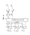
- Fig. 6 shows the configuration of the second embodiment.
- reference numerals 21, 22, 23, 24, 25 and 26 represent a writing-head selector, a masking-head selector, a reading-head selector, a first MPX code, a second MPX code and a third MPX code, respectively.
- Each of the selectors 21 - 23 is preferably constituted by a MPX device.
- Figs. 7A and 7B show an embodiment of the configuration of Fig. 6.
- Reference numerals 27, 28 and 29 represent a first MPX register, a second MPX register and a third MPX register, respectively.
- Fig. 8 is a time chart of signals read by the-picture image reading device of Fig. 2.
- the original document A is scanned along the line.a to read the original document A.
- the read-out information is subject to binary transformation to obtain binary signal a' of Fig. 8.
- the first MPX code 24 is set to select only the first magnetic head 4a 1 . Therefore, the signal a' is transferred to a DK write-in signal 6 to the writing-head selector 21.
- the signal a' is then outputted from the writing-head selector 21 through the line la l , and is applied to a first magnetic head 4a l through the line 3a 1 .
- the first magnetic head 4a 1 stores the signal a' in a predetermined region P 1 -P 6 (Fig. 8) on a predetermined track on an upper surface of a DK board 5a 1 .
- the mask B is read along the line b and the mask information (in which the portion corresponding to the position of the original document A to be recorded is made to be a logical "1") is written by a second magnetic head 4a 2 on the lower surface of the DK board 5a 1 , as shown in b' of F ig. 8.
- a logical "1" signal is stored as the mask information b' at the portion P 1 -P 2 on a predetermined track.
- the original document C which contains the information to be posted or moved is read along the line c as shown in Fig. 2.
- the read-out information c' (Fig. 8) is moved to the position P 4 - P 5 to be recorded by a magnetic head 4a3 onto an upper surface of a DK board 5a2.
- the information c" has been stored in the position P 4 -P 5 on the predetermined track.
- the second MPX code 25 is set to simultaneously access the first and second magnetic heads 4a l and 4a 2 and the third MPX code 26 set to access the third magnetic head 4a3.
- the second MPX code 25 is set to simultaneously access the magnetic heads 4a 1 and 4a 2
- each of the signals on the lines 28a 1 and 28a 2 connected to the MPX code register 28 are at a "1" state, while each of the signals on the remainder lines 28a c -28a 2n are at a "0" state.
- the c outputs of both the first and second magnetic heads 4a l and 4a 2 are "1" (namely, when the signals on both the lines 2a l and 2a 2 are "1") a logical "1" output is obtained from an AND gate 30.
- the output of the AND gate 30 is the information of the original document A which is covered by the mask B.
- the signal on the line 29a3 connected to the third MPX code register is a logical "1" while the signals on the other lines remain a logical "0".
- the signal read out by the third magnetic head 4a3 is outputted from an OR gate 31.
- a DK read-out signal 7 having a waveform d' of Fig. 8 is outputted from the masking-head selector 22.
- the document D of Fig. 2 is obtained, wherein the original document C is posted or moved to the position of the original document A which is covered by the mask B.
- the'steps (4') - (8') of the second prior art image processing method can be obtained similarly to that of the first embodiment of the invention. As such, the picture image processing time can be reduced accordingly.
- This embodiment is preferably used in the case of a so-called compounding description, in which a large character is expressed in terms of a plurality of small characters.
Landscapes
- Engineering & Computer Science (AREA)
- Multimedia (AREA)
- Signal Processing (AREA)
- Storing Facsimile Image Data (AREA)
- Information Retrieval, Db Structures And Fs Structures Therefor (AREA)
- Television Signal Processing For Recording (AREA)
- Recording Or Reproducing By Magnetic Means (AREA)
- Processing Or Creating Images (AREA)
- Editing Of Facsimile Originals (AREA)
Applications Claiming Priority (2)
| Application Number | Priority Date | Filing Date | Title |
|---|---|---|---|
| JP195710/81 | 1981-12-07 | ||
| JP56195710A JPS5897767A (ja) | 1981-12-07 | 1981-12-07 | 画像処理用磁気デイスク制御方法および装置 |
Publications (3)
| Publication Number | Publication Date |
|---|---|
| EP0081375A2 true EP0081375A2 (fr) | 1983-06-15 |
| EP0081375A3 EP0081375A3 (en) | 1986-05-14 |
| EP0081375B1 EP0081375B1 (fr) | 1989-04-19 |
Family
ID=16345681
Family Applications (1)
| Application Number | Title | Priority Date | Filing Date |
|---|---|---|---|
| EP82306504A Expired EP0081375B1 (fr) | 1981-12-07 | 1982-12-07 | Procédé de commande de disques magnétiques pour le traitement d'images et appareil pour celui-ci |
Country Status (4)
| Country | Link |
|---|---|
| US (1) | US4551769A (fr) |
| EP (1) | EP0081375B1 (fr) |
| JP (1) | JPS5897767A (fr) |
| DE (1) | DE3279638D1 (fr) |
Cited By (3)
| Publication number | Priority date | Publication date | Assignee | Title |
|---|---|---|---|---|
| GB2183428A (en) * | 1985-10-07 | 1987-06-03 | Canon Kk | Pattern forming apparatus |
| GB2220331A (en) * | 1985-10-07 | 1990-01-04 | Canon Kk | Image processing |
| EP0449313A3 (en) * | 1990-03-30 | 1992-12-16 | Canon Kabushiki Kaisha | Image processing method and apparatus |
Families Citing this family (7)
| Publication number | Priority date | Publication date | Assignee | Title |
|---|---|---|---|---|
| US4731672A (en) * | 1983-11-25 | 1988-03-15 | Canon Kabushiki Kaisha | Image processing system |
| JPH0824333B2 (ja) * | 1985-01-31 | 1996-03-06 | キヤノン株式会社 | 画像処理装置 |
| DE3672609D1 (de) * | 1986-04-30 | 1990-08-16 | Hell Rudolf Dr Ing Gmbh | Verfahren zur aufzeichnung von druckformen. |
| DE10047088C2 (de) | 2000-09-21 | 2002-10-17 | Gerhard Weber | Medium für analytische und präparative Elektrophorese |
| DE10063097B4 (de) | 2000-12-18 | 2007-04-19 | Becton, Dickinson And Co. | Elektrophoresevorrichtung |
| DE10063096C1 (de) | 2000-12-18 | 2002-09-12 | Gerhard Weber | Elektrophoresevorrichtung, Elektrophoreseverfahren unter Verwendung einer Elektrophoresevorrichtung und Verwendung der Elektrophoresevorrichtung |
| DE102005020134A1 (de) | 2005-04-29 | 2006-11-02 | Becton, Dickinson And Co. | Verfahren und Vorrichtung zur Durchführung eines parallelen und simultanen Mehrfachprozesses der trägerfreien isoelektrischen Fokussierung |
Family Cites Families (5)
| Publication number | Priority date | Publication date | Assignee | Title |
|---|---|---|---|---|
| US4302782A (en) * | 1977-03-10 | 1981-11-24 | Xerox Corporation | Reproduction scanning system having intermediate storage between input and output scanning stations |
| US4205350A (en) * | 1977-03-10 | 1980-05-27 | Xerox Corporation | Reproduction scanning system having intermediate storage between input and output scanning stations |
| DE2720944A1 (de) * | 1977-05-10 | 1978-11-16 | Hell Rudolf Dr Ing Gmbh | Verfahren und einrichtung zur herstellung von bildkombinationen |
| US4245247A (en) * | 1979-07-19 | 1981-01-13 | Eastman Kodak Company | Hard copy reproduction from video disc information |
| JPS5761372A (en) * | 1980-09-30 | 1982-04-13 | Toshiba Corp | Image recorder |
-
1981
- 1981-12-07 JP JP56195710A patent/JPS5897767A/ja active Granted
-
1982
- 1982-12-06 US US06/447,363 patent/US4551769A/en not_active Expired - Lifetime
- 1982-12-07 DE DE8282306504T patent/DE3279638D1/de not_active Expired
- 1982-12-07 EP EP82306504A patent/EP0081375B1/fr not_active Expired
Cited By (6)
| Publication number | Priority date | Publication date | Assignee | Title |
|---|---|---|---|---|
| GB2183428A (en) * | 1985-10-07 | 1987-06-03 | Canon Kk | Pattern forming apparatus |
| GB2220331A (en) * | 1985-10-07 | 1990-01-04 | Canon Kk | Image processing |
| GB2183428B (en) * | 1985-10-07 | 1990-08-29 | Canon Kk | Image processing system |
| GB2220331B (en) * | 1985-10-07 | 1990-09-12 | Canon Kk | Image processing system |
| EP0449313A3 (en) * | 1990-03-30 | 1992-12-16 | Canon Kabushiki Kaisha | Image processing method and apparatus |
| US5596426A (en) * | 1990-03-30 | 1997-01-21 | Canon Kabushiki Kaisha | Image processing method and apparatus |
Also Published As
| Publication number | Publication date |
|---|---|
| EP0081375A3 (en) | 1986-05-14 |
| EP0081375B1 (fr) | 1989-04-19 |
| DE3279638D1 (en) | 1989-05-24 |
| JPS5897767A (ja) | 1983-06-10 |
| JPS6261985B2 (fr) | 1987-12-24 |
| US4551769A (en) | 1985-11-05 |
Similar Documents
| Publication | Publication Date | Title |
|---|---|---|
| US4003024A (en) | Two-dimensional binary data enhancement system | |
| US4636848A (en) | Document information filing system with a single display device | |
| US5129011A (en) | Method and apparatus for retrieving image data | |
| US3582884A (en) | Multiple-scanner character reading system | |
| EP0051218B2 (fr) | Système pour l'enregistrement des informations d'image | |
| US4551769A (en) | Picture image processing magnetic disc controlling method and apparatus therefor | |
| KR950033954A (ko) | 영상처리장치 | |
| US4627097A (en) | Method and apparatus for improved printing in a selected orientation | |
| US5182651A (en) | Method of controlling the reception of data | |
| US4051457A (en) | System for generating a character pattern | |
| US3806871A (en) | Multiple scanner character reading system | |
| US5432614A (en) | Electronic filing apparatus | |
| US4400777A (en) | Information processing system for a computer output microfilmer | |
| US4453227A (en) | Method and apparatus for transferring a bit pattern field into a memory | |
| US4776028A (en) | Apparatus for and method of compressing form data | |
| US4942542A (en) | Image processing computer system optimized to reduce idle time of computer | |
| JPS6231546B2 (fr) | ||
| US5910794A (en) | Method and apparatus for storing and rotating bit patterns | |
| US5319794A (en) | Device for high-speed processing of information frames | |
| JPS5853272A (ja) | 画像デ−タ圧縮および再生方式 | |
| US6577313B1 (en) | Image data control apparatus | |
| JPH0134497B2 (fr) | ||
| JPH08183208A (ja) | ビットマップ記録方法および記録装置 | |
| JP3099540B2 (ja) | 光学式文字読取装置で用いるイメージ格納方法 | |
| JP3450492B2 (ja) | シリアル記録装置 |
Legal Events
| Date | Code | Title | Description |
|---|---|---|---|
| PUAI | Public reference made under article 153(3) epc to a published international application that has entered the european phase |
Free format text: ORIGINAL CODE: 0009012 |
|
| AK | Designated contracting states |
Designated state(s): DE GB |
|
| PUAL | Search report despatched |
Free format text: ORIGINAL CODE: 0009013 |
|
| AK | Designated contracting states |
Kind code of ref document: A3 Designated state(s): DE GB |
|
| 17P | Request for examination filed |
Effective date: 19860718 |
|
| 17Q | First examination report despatched |
Effective date: 19871103 |
|
| GRAA | (expected) grant |
Free format text: ORIGINAL CODE: 0009210 |
|
| AK | Designated contracting states |
Kind code of ref document: B1 Designated state(s): DE GB |
|
| REF | Corresponds to: |
Ref document number: 3279638 Country of ref document: DE Date of ref document: 19890524 |
|
| PLBE | No opposition filed within time limit |
Free format text: ORIGINAL CODE: 0009261 |
|
| STAA | Information on the status of an ep patent application or granted ep patent |
Free format text: STATUS: NO OPPOSITION FILED WITHIN TIME LIMIT |
|
| 26N | No opposition filed | ||
| PGFP | Annual fee paid to national office [announced via postgrant information from national office to epo] |
Ref country code: GB Payment date: 19941129 Year of fee payment: 13 |
|
| PGFP | Annual fee paid to national office [announced via postgrant information from national office to epo] |
Ref country code: DE Payment date: 19941208 Year of fee payment: 13 |
|
| PG25 | Lapsed in a contracting state [announced via postgrant information from national office to epo] |
Ref country code: DE Effective date: 19950127 |
|
| PG25 | Lapsed in a contracting state [announced via postgrant information from national office to epo] |
Ref country code: GB Effective date: 19951207 |
|
| GBPC | Gb: european patent ceased through non-payment of renewal fee |
Effective date: 19951207 |