EP0081378A2 - Remplissage d'une gaine de barreau combustible avec des sphères nucléaires de dimensions diverses - Google Patents
Remplissage d'une gaine de barreau combustible avec des sphères nucléaires de dimensions diverses Download PDFInfo
- Publication number
- EP0081378A2 EP0081378A2 EP82306517A EP82306517A EP0081378A2 EP 0081378 A2 EP0081378 A2 EP 0081378A2 EP 82306517 A EP82306517 A EP 82306517A EP 82306517 A EP82306517 A EP 82306517A EP 0081378 A2 EP0081378 A2 EP 0081378A2
- Authority
- EP
- European Patent Office
- Prior art keywords
- fuel
- spheres
- tubes
- loading
- tubing
- Prior art date
- Legal status (The legal status is an assumption and is not a legal conclusion. Google has not performed a legal analysis and makes no representation as to the accuracy of the status listed.)
- Granted
Links
Images


Classifications
-
- G—PHYSICS
- G21—NUCLEAR PHYSICS; NUCLEAR ENGINEERING
- G21C—NUCLEAR REACTORS
- G21C21/00—Apparatus or processes specially adapted to the manufacture of reactors or parts thereof
- G21C21/02—Manufacture of fuel elements or breeder elements contained in non-active casings
- G21C21/04—Manufacture of fuel elements or breeder elements contained in non-active casings by vibrational compaction or tamping of fuel in the jacket
-
- Y—GENERAL TAGGING OF NEW TECHNOLOGICAL DEVELOPMENTS; GENERAL TAGGING OF CROSS-SECTIONAL TECHNOLOGIES SPANNING OVER SEVERAL SECTIONS OF THE IPC; TECHNICAL SUBJECTS COVERED BY FORMER USPC CROSS-REFERENCE ART COLLECTIONS [XRACs] AND DIGESTS
- Y02—TECHNOLOGIES OR APPLICATIONS FOR MITIGATION OR ADAPTATION AGAINST CLIMATE CHANGE
- Y02E—REDUCTION OF GREENHOUSE GAS [GHG] EMISSIONS, RELATED TO ENERGY GENERATION, TRANSMISSION OR DISTRIBUTION
- Y02E30/00—Energy generation of nuclear origin
- Y02E30/30—Nuclear fission reactors
Definitions
- the present invention relates to the loading of fuel rods with spherical nuclear fuel.
- One method for loading a fuel rod is to simply drop the spheres into a vertical cladding tube while vibrating the rod to assist in packing.
- this method is not satisfactory for several reasons.
- the distribution of the particles sizes freely falling from a height of 6 to 12 feet into a cladding tube does not lead to uniform distribution.
- This method also leads to the trapping of air which requires a longer time to evacuate at the sealing of the tube.
- the vibrating packing is extended because of the random loading of the spheres.
- a loading device for loading different-sized spheres (or the like) of nuclear fuel into a rod sheath, characterised by means (64, 100, 108) for separately delivering a metered quantity of spheres of nuclear fuel of each different size to the fuel rod sheath, said delivery means including means (114) for regulating the flow rate for each size of nuclear fuel sphere delivered to said sheath (2).
- a loading device for loading spheres (or the like) of nuclear fuel of a plurality (for example three) of different diameters into a fuel rod characterised by:
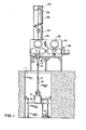
- FIG. 1 shows the system viewed from the front.
- a fuel cladding rod 2 in the form of a sheath to be loaded with fuel is held vertically upright by a fuel rod support clamp 4. Because of the length of the fuel rods 2, the rods 2 may be set in pit 1 in the building floor.
- the support claim 4 is fixed to a vibrator 6 driven by vibrator motor 88.
- the vibrator 6 rests on a frame 10.
- the frame 10 is vertically adjustable to give the vibrator 6 a vertical travel of several feet. This allows the loading system to accommodate fuel cladding rods 2 of different lengths.
- the open upper end of the fuel cladding tube 2 is attached to an adaptor 18 with an airtight connection.
- the adaptor 18 is mounted to the glove box 22 via a bellows arrangement so that the fuel tube 2 is flexibly mounted to the glove box 22 allowing the fuel tube 2 to vibrate in response to the vibrator 6 while the tube is being loaded.
- the adaptor 18 is connected to the glove box 22 with a vacuum valve 24 so that the adaptor 18 and fuel tube 2 combination may be isolated from the glove box 22 forming an airtight combination.
- the glove box 22 is an enclosure capable of being made airtight which receives the nuclear fuel through the entrance vacuum valve 26.
- the glove box includes windows 28 and hinged glove box covers 30. Opening the glove box covers 30 reveals gloves (not shown) mounted to the glove box 22 which allows the operator to accomplish manipulation within the glove box 22 while still retaining the inert atmosphere within the glove box 22.
- On the upper side and connected to the glove box 22 is the rod loading assembly cover 32.
- the rod loading assembly cover 32 is of sufficient length to allow the. rod loading assembly 34 to rise high enough so that it is free of the fuel cladding tube 2.
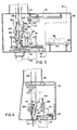
- Figure 3 shows a side view of the glove box and fuel cladding tube assembly.
- FIG. 4 shows the passage of the spherical nuclear fuel from the entrance vacuum valve 26 to the loading hoppers 60 and 62 of the weighing stations.
- the nuclear fuel spheres enter the glove box 22 through the entrance vacuum valve 26 in containers large enough to hold sufficient fuel for about six fuel tubes 2.
- the fuel containers 36 indicated by the dotted lines move along the rollers 40 of the transport conveyer 38, which may be powered or non-powered. After coming to rest on the conveyor 38, the fuel is lifted vertically upward by the overhead transport system 42.
- the over head transport system 42 is capable of lifting the fuel container 36 from the transport conveyor 38 and moving it from right to left and back and forth within the glove box 22.
- the overhead transport conveyor 38 includes a rotating drum 43 around which is wrapped a cord 44 for raising and lowering the spheres.
- the containers 36- are moved one at a time from the transport conveyor-38 to the loading hoppers 60 and 62 of the weighing scales.
- _ three sizes of spheres are used, which are referred to herein as fines, mediums and large.
- the mediums weighing station 66 is shown in Figure 3 by the dotted figure in the load position for receiving fuel.
- the fuel container 36 are attached to the transport lid 43 and moved by the overhead transport system 42 to each of the weighing stations where the fuel spheres are deposited into the hoppers 60 and 62 of the scales.
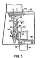
- the mediums 66 and large (not shown but labelled 65 for convenience of reference) weighing stations are mounted on one platform and move from side to side by the drive motor 68.
- the weighing stations move up and down by the drive mechanism 72, the glove box 22 providing a recess 75 for the support shaft 76 when the station is lowered.
- the fines weighing station 64 moves front to back driven by the drive motor 78 within the glove box 22 as well as side to side motion driven by motor 70.
- the mediums 66 and large 65 weighing stations are mounted on one platform moved toward the glove box opening for loading.
- the large (not shown but designated 61 for convenience of reference) and mediums 62 weighing stations loading hoppers are lowered to accommodate the fuel containers 36 which are moved to the weighing stations by the overhead fuel transport 42.
- the fines weighing system 64 is mounted independently of weighing stations 65 and 66 and moves towards the back of the glove box 22, then to the right and down for loading.
- the fuel spheres containers 36 are picked up by the overhead transport system 42 and positioned on top of the weighing station hoppers. The spheres are released into the loading hoppers 60, 61 and 62.
- Spheres of each size are dropped into the weighing scales hoppers 80 and 82 in incremental amounts by the stepper motors 84 and 86.
- the flow ceases (Recall only two of the three weighing scales are shown in the Figures).
- These predetermined amounts of fuel spheres are sufficient to fill one fuel rod 2.
- These fuel spheres are then released to the hoppers 92, 94, and 96 of the feeding probe 34.
- the feeding probe 34 is a device for depositing the three different sizes of spheres into the fuel rod 2 in a controlled manner so that the correct uniform density is achieved in the rod 2.
- the probe 34 includes three funnels 92, 94 and 96 into which each of the three quantities of fuel is discharged from the weighing scale hoppers 80, 81 and 82.
- the funnels are spaced about 60° apart and are all identical except for the ability to accommodate different sized spherical fuel.
- the three funnels 92, 94 and 96 are connected to the probe hopper 98 via three solenoid valves 100. There is one solenoid valve 100 for each funnel.
- the probe hopper 98 is divided into three sections.
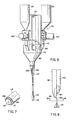
- the fuel spheres after being released by the solenoid valves 100, pass through a regulator gate 114 shown in Figure 9 which is of V-shaped configuration as viewed from the side as shown.
- the gate 114 is releasably attached by conventional ball plunger means 115 to the hopper 98 so as to restrict the passageway 116 connecting the funnels 92 to the sections 102, 104 and 106 of the probe hopper 98.
- the gate 114 includes an opening of height h and width w. These dimensions are selected according to the size of nuclear fuel spheres and the desired rate of flow into the probe hopper 98. The rate of flow of each of the fuel spheres is determined so that upon emergence from the probe 34 within the fuel rod 2, the maximum randomness of the three different size spheres is achieved.
- the probe hopper 98 is connected to tubing 108, 110 and 112. Each of these tubes corresponds to one of the sections of the probe hopper 98 which, in turn, corresponds to one of the funnels 92, 94 and 96. 'In the particular embodiment shown in Figures 6 and 10, two of the tubes 108 and 110 are of the same circular cross-section. These tubes are used for the two smallest diameter fuel. The largest fuel sphere is carried by the tube 112 of elliptical cross section.
- each of the tubes 108, 110 and 112 is extended into scoops as shown in Figures 8 and 10.
- the scoop shaped extensions terminate into points 116 and 177 toward the axis through the centre of the three tubed arrangement.
- the extensions of tubes 108 and 110 for the two smaller tubes join together to form one common point 117. These extensions help in the mixing of the fuel spheres to provide a random distribution of packing of the fuel tube.
- a cone shaped piece 118 is fixed to the lower end of the fuel tubes 108, 110 and 112 by two cylindrical rod members 13 0 as shown in Figure 8.
- the cone 118 is fixed to the rods 130 by conventional means.
- the cone 118 may be fixed to the lower end of the fuel tubes 108, 110, and 112 by a cylindrical collar 119.
- the collar overlaps and is welded to the lower end of the fuel tubes.
- the cone 118 is fixed to the other end of the collar 118 with the point of the cone 118 along the axis of the collar and pointed toward the probe 34.
- the cone 118 is welded at several points 121 but leaving a gap 123 between the cone 118 and colar 119 so that the fuel spheres may emerge from the probe 34.
- the weighing stations are moved out of the way of the fuel feeding probe 90 and the solenoid valves 100 are opened.
- the fuel spheres descend through the valve 100, the regulator gate 114 and the tubing 108, 110 and 112.
- the probe 90 is raised at a rate so that the bottom of the fuel probe 90 remains just above the ascending fuel column. That is, the spheres are deposited on top of the fuel column such that the end of the probe remains between about 1 and 5 in above the ascending fuel column.
- the probe 34 is raised and lowered by means 33 through a cable 35 attached to Bracket 31 of the probe 34.
- Copper tubes 132 guide the feeding probe 90 up and down.
- the copper tubes 132 in combination with wires 134 provide the electrical contact to operate the solenoids 100.
- the vibrator 6 is in operation while the fuel rod 2 is being loaded. After the loading is completed and feeding probe 90 is clear of the fuel rod 2, the rod is removed from the support clamp 4. A new fuel rod is placed in the clamp 4 and process is started again.
Landscapes
- Engineering & Computer Science (AREA)
- Physics & Mathematics (AREA)
- Manufacturing & Machinery (AREA)
- Plasma & Fusion (AREA)
- General Engineering & Computer Science (AREA)
- High Energy & Nuclear Physics (AREA)
- Monitoring And Testing Of Nuclear Reactors (AREA)
- Instruments For Viewing The Inside Of Hollow Bodies (AREA)
Applications Claiming Priority (2)
| Application Number | Priority Date | Filing Date | Title |
|---|---|---|---|
| US327816 | 1981-12-07 | ||
| US06/327,816 US4495145A (en) | 1981-12-07 | 1981-12-07 | Spherical nuclear fuel loading probe |
Publications (3)
| Publication Number | Publication Date |
|---|---|
| EP0081378A2 true EP0081378A2 (fr) | 1983-06-15 |
| EP0081378A3 EP0081378A3 (en) | 1984-10-24 |
| EP0081378B1 EP0081378B1 (fr) | 1987-11-11 |
Family
ID=23278191
Family Applications (1)
| Application Number | Title | Priority Date | Filing Date |
|---|---|---|---|
| EP82306517A Expired EP0081378B1 (fr) | 1981-12-07 | 1982-12-07 | Remplissage d'une gaine de barreau combustible avec des sphères nucléaires de dimensions diverses |
Country Status (4)
| Country | Link |
|---|---|
| US (1) | US4495145A (fr) |
| EP (1) | EP0081378B1 (fr) |
| JP (1) | JPS58105095A (fr) |
| DE (1) | DE3277660D1 (fr) |
Cited By (3)
| Publication number | Priority date | Publication date | Assignee | Title |
|---|---|---|---|---|
| EP0081379A3 (en) * | 1981-12-07 | 1984-11-07 | Exxon Nuclear Company Inc. | Loading fuel rod with nuclear spheres |
| EP0192137A3 (en) * | 1985-02-19 | 1987-11-19 | Westinghouse Electric Corporation | Manufacturing automation system for nuclear fuel rod production |
| EP0449479A1 (fr) * | 1990-03-22 | 1991-10-02 | The Babcock & Wilcox Company | Dispositif mélangeur et de chargement de marériaux de densités différentes |
Families Citing this family (3)
| Publication number | Priority date | Publication date | Assignee | Title |
|---|---|---|---|---|
| GB2183039B (en) * | 1985-11-18 | 1989-10-04 | British Nuclear Fuels Plc | Stack forming apparatus |
| JPH0230311A (ja) * | 1988-04-18 | 1990-01-31 | Kawasaki Steel Corp | 継目無鋼管の傾斜圧延方法 |
| JPH0230312A (ja) * | 1988-04-18 | 1990-01-31 | Kawasaki Steel Corp | 継目無鋼管の熱間圧延方法 |
Family Cites Families (13)
| Publication number | Priority date | Publication date | Assignee | Title |
|---|---|---|---|---|
| US2460605A (en) * | 1941-05-07 | 1949-02-01 | Certain Teed Prod Corp | Apparatus for feeding flowable material from a plurality of containers |
| US2724535A (en) * | 1951-10-04 | 1955-11-22 | Crown Cork & Seal Co | Filling valve for apparatus for filling containers with liquid |
| GB743424A (en) * | 1953-04-23 | 1956-01-18 | Keir & Cawder Ltd | Device and apparatus for controlled discharge of granular material |
| US2867247A (en) * | 1956-06-04 | 1959-01-06 | Kuner Empson Company | Feed tube |
| US2983658A (en) * | 1956-11-30 | 1961-05-09 | Herbert H Hyman | Heterogeneous nuclear reactor employing small unclad bodies of fissionable material as fuel |
| US3100742A (en) * | 1958-03-17 | 1963-08-13 | Atomic Energy Commission | Fuel element for a neutronic reactor |
| US3572405A (en) * | 1968-06-06 | 1971-03-23 | Atomic Energy Commission | Apparatus for blending particles |
| CH533537A (de) * | 1970-12-21 | 1973-02-15 | Gericke & Co | Vorrichtung zum Abfüllen eines Behältnisses mit verdichtetem, pulvrigem Gut |
| US3778348A (en) * | 1971-02-12 | 1973-12-11 | Atomic Energy Commission | Nuclear fuel element with axially aligned fuel pellets and fuel microspheres therein |
| US3901409A (en) * | 1974-07-23 | 1975-08-26 | Us Energy | Apparatus for blending small particles |
| US4111335A (en) * | 1976-03-15 | 1978-09-05 | General Atomic Company | Metering system |
| US4134393A (en) * | 1976-07-09 | 1979-01-16 | Virgil Stark | Solar energy collection |
| US4495146A (en) * | 1981-12-07 | 1985-01-22 | Exxon Nuclear Company, Inc. | Spherical nuclear fuel loading system |
-
1981
- 1981-12-07 US US06/327,816 patent/US4495145A/en not_active Expired - Fee Related
-
1982
- 1982-12-07 JP JP57213454A patent/JPS58105095A/ja active Granted
- 1982-12-07 EP EP82306517A patent/EP0081378B1/fr not_active Expired
- 1982-12-07 DE DE8282306517T patent/DE3277660D1/de not_active Expired
Cited By (3)
| Publication number | Priority date | Publication date | Assignee | Title |
|---|---|---|---|---|
| EP0081379A3 (en) * | 1981-12-07 | 1984-11-07 | Exxon Nuclear Company Inc. | Loading fuel rod with nuclear spheres |
| EP0192137A3 (en) * | 1985-02-19 | 1987-11-19 | Westinghouse Electric Corporation | Manufacturing automation system for nuclear fuel rod production |
| EP0449479A1 (fr) * | 1990-03-22 | 1991-10-02 | The Babcock & Wilcox Company | Dispositif mélangeur et de chargement de marériaux de densités différentes |
Also Published As
| Publication number | Publication date |
|---|---|
| US4495145A (en) | 1985-01-22 |
| EP0081378A3 (en) | 1984-10-24 |
| DE3277660D1 (en) | 1987-12-17 |
| EP0081378B1 (fr) | 1987-11-11 |
| JPS58105095A (ja) | 1983-06-22 |
| JPH0365518B2 (fr) | 1991-10-14 |
Similar Documents
| Publication | Publication Date | Title |
|---|---|---|
| EP0081379B1 (fr) | Remplissage d'une barre combustible avec des sphères nucléaires | |
| US5897282A (en) | Catalytic reactor charging system and method for operation thereof | |
| JP2701905B2 (ja) | サイロ車輌等に粉粒物を積載する装置 | |
| US6203261B1 (en) | Adjustable reclaiming device for moving bulk material | |
| US20010041117A1 (en) | Catalytic reactor charging system and method for operation thereof | |
| EP1117590A1 (fr) | Appareil de remplissage et de pesage pour remplir des sacs | |
| US4495145A (en) | Spherical nuclear fuel loading probe | |
| US3881610A (en) | Loading apparatus or loading head for loose material | |
| GB2103950A (en) | Process and apparatus for mixing bulk materials in a container | |
| RU2180265C1 (ru) | Способ и устройство для загрузки частиц в трубу трубчатого реактора | |
| CN113911756A (zh) | 集装箱散货装箱装置及其控制方法 | |
| EP0686588A2 (fr) | Appareil de manutention de matériaux | |
| CN111965079B (zh) | 一种全自动放矿模拟试验装置 | |
| WO1998014392A1 (fr) | Systeme et procede de chargement d'un reacteur catalytique | |
| CH676297A5 (fr) | ||
| WO1998002238A1 (fr) | Mecanisme de remplissage d'un reacteur a tubes | |
| JPH07315302A (ja) | 粉体の定量充填装置およびこれに用いる弁 | |
| CN215972200U (zh) | 垂直加料直装秤 | |
| CN213008935U (zh) | 一种物料打包系统 | |
| CA2038870C (fr) | Melangeur de produits de densites diverses | |
| CN209241457U (zh) | 一种自动称量输送装置 | |
| EP4663563A1 (fr) | Agencement de dispositif de décharge de sacs | |
| JPH06138004A (ja) | 放射性流体を収容したポットを、サンプリング装置と分析チェインとの間で輸送、計量する自動操作装置 | |
| CN217754352U (zh) | 粒状物体自动装填机构 | |
| GB1590287A (en) | Apparatus for the injection of additive material into a melt |
Legal Events
| Date | Code | Title | Description |
|---|---|---|---|
| PUAI | Public reference made under article 153(3) epc to a published international application that has entered the european phase |
Free format text: ORIGINAL CODE: 0009012 |
|
| AK | Designated contracting states |
Designated state(s): BE CH DE FR GB LI SE |
|
| PUAL | Search report despatched |
Free format text: ORIGINAL CODE: 0009013 |
|
| AK | Designated contracting states |
Designated state(s): BE CH DE FR GB LI SE |
|
| 17P | Request for examination filed |
Effective date: 19850306 |
|
| 17Q | First examination report despatched |
Effective date: 19860520 |
|
| RAP1 | Party data changed (applicant data changed or rights of an application transferred) |
Owner name: SIEMENS AKTIENGESELLSCHAFT BERLIN UND MUENCHEN |
|
| GRAA | (expected) grant |
Free format text: ORIGINAL CODE: 0009210 |
|
| AK | Designated contracting states |
Kind code of ref document: B1 Designated state(s): BE CH DE FR GB LI SE |
|
| REF | Corresponds to: |
Ref document number: 3277660 Country of ref document: DE Date of ref document: 19871217 |
|
| ET | Fr: translation filed | ||
| PLBE | No opposition filed within time limit |
Free format text: ORIGINAL CODE: 0009261 |
|
| STAA | Information on the status of an ep patent application or granted ep patent |
Free format text: STATUS: NO OPPOSITION FILED WITHIN TIME LIMIT |
|
| 26N | No opposition filed | ||
| PGFP | Annual fee paid to national office [announced via postgrant information from national office to epo] |
Ref country code: GB Payment date: 19901116 Year of fee payment: 9 |
|
| PGFP | Annual fee paid to national office [announced via postgrant information from national office to epo] |
Ref country code: SE Payment date: 19901212 Year of fee payment: 9 |
|
| PGFP | Annual fee paid to national office [announced via postgrant information from national office to epo] |
Ref country code: FR Payment date: 19901219 Year of fee payment: 9 |
|
| PGFP | Annual fee paid to national office [announced via postgrant information from national office to epo] |
Ref country code: BE Payment date: 19901228 Year of fee payment: 9 |
|
| PGFP | Annual fee paid to national office [announced via postgrant information from national office to epo] |
Ref country code: DE Payment date: 19910225 Year of fee payment: 9 |
|
| PGFP | Annual fee paid to national office [announced via postgrant information from national office to epo] |
Ref country code: CH Payment date: 19910322 Year of fee payment: 9 |
|
| PG25 | Lapsed in a contracting state [announced via postgrant information from national office to epo] |
Ref country code: GB Effective date: 19911207 |
|
| PG25 | Lapsed in a contracting state [announced via postgrant information from national office to epo] |
Ref country code: SE Effective date: 19911208 |
|
| PG25 | Lapsed in a contracting state [announced via postgrant information from national office to epo] |
Ref country code: LI Effective date: 19911231 Ref country code: CH Effective date: 19911231 Ref country code: BE Effective date: 19911231 |
|
| BERE | Be: lapsed |
Owner name: SIEMENS A.G. BERLIN UND MUNCHEN Effective date: 19911231 |
|
| GBPC | Gb: european patent ceased through non-payment of renewal fee | ||
| PG25 | Lapsed in a contracting state [announced via postgrant information from national office to epo] |
Ref country code: FR Effective date: 19920831 |
|
| REG | Reference to a national code |
Ref country code: CH Ref legal event code: PL |
|
| PG25 | Lapsed in a contracting state [announced via postgrant information from national office to epo] |
Ref country code: DE Effective date: 19920901 |
|
| REG | Reference to a national code |
Ref country code: FR Ref legal event code: ST |
|
| EUG | Se: european patent has lapsed |
Ref document number: 82306517.2 Effective date: 19920704 |