EP0081379A2 - Remplissage d'une barre combustible avec des sphères nucléaires - Google Patents
Remplissage d'une barre combustible avec des sphères nucléaires Download PDFInfo
- Publication number
- EP0081379A2 EP0081379A2 EP82306518A EP82306518A EP0081379A2 EP 0081379 A2 EP0081379 A2 EP 0081379A2 EP 82306518 A EP82306518 A EP 82306518A EP 82306518 A EP82306518 A EP 82306518A EP 0081379 A2 EP0081379 A2 EP 0081379A2
- Authority
- EP
- European Patent Office
- Prior art keywords
- fuel
- spheres
- weighing
- loading
- fuel rod
- Prior art date
- Legal status (The legal status is an assumption and is not a legal conclusion. Google has not performed a legal analysis and makes no representation as to the accuracy of the status listed.)
- Granted
Links
Images



Classifications
-
- G—PHYSICS
- G21—NUCLEAR PHYSICS; NUCLEAR ENGINEERING
- G21C—NUCLEAR REACTORS
- G21C21/00—Apparatus or processes specially adapted to the manufacture of reactors or parts thereof
- G21C21/02—Manufacture of fuel elements or breeder elements contained in non-active casings
- G21C21/04—Manufacture of fuel elements or breeder elements contained in non-active casings by vibrational compaction or tamping of fuel in the jacket
-
- Y—GENERAL TAGGING OF NEW TECHNOLOGICAL DEVELOPMENTS; GENERAL TAGGING OF CROSS-SECTIONAL TECHNOLOGIES SPANNING OVER SEVERAL SECTIONS OF THE IPC; TECHNICAL SUBJECTS COVERED BY FORMER USPC CROSS-REFERENCE ART COLLECTIONS [XRACs] AND DIGESTS
- Y02—TECHNOLOGIES OR APPLICATIONS FOR MITIGATION OR ADAPTATION AGAINST CLIMATE CHANGE
- Y02E—REDUCTION OF GREENHOUSE GAS [GHG] EMISSIONS, RELATED TO ENERGY GENERATION, TRANSMISSION OR DISTRIBUTION
- Y02E30/00—Energy generation of nuclear origin
- Y02E30/30—Nuclear fission reactors
Definitions
- the present invention is concerned with the loading of fuel rods with spheres (or the like) of nuclear fuel.
- One method for loading a fuel rod is to simply drop the spheres into a vertical cladding tube while vibrating the rod to assist in packing.
- this method is not satisfactory for several reasons.
- the distribution of the particles sizes freely falling from a height of 6 to 12 feet into a cladding tube does not lead to uniform distribution.
- This method also leads to the trapping of air which requires a longer time to evacuate at the sealing of the tube.
- the vibrating packing is extended because of the random loading of the spheres.
- a loading system for loading different-sized spheres (or the like) of nuclear fuel into a fuel rod sheath, characterized by means for delivering and metering nuclear fuel spheres of each different size to the fuel rod sheath, including means for weighing a given quantity of fuel spheres Of each size prior to delivery to said sheath.
- a loading system for loading different-sized spheres (or the like) of nuclear fuel into a rod sheath, characterized by means for separately delivering and metering spheres of nuclear fuel of each different size to the fuel rod sheath, whereby a given quantity of each size of spheres of nuclear fuel is precisely delivered to said fuel rod sheath.
- a system for loading spheres (or the like) of nuclear fuel into an upright fuel rod characterised by :
- a preferred loading system includes a main housing having an inert atmosphere and having an opening to receive fuel spheres having three different diameters for loading into fuel rods; a weighing station system for receiving the spheres and separating the spheres into three predetermined quantities, the weighing system including a balance means for weighing the nuclear fuel spheres; a means for transferring the fuel spheres after entering the housing to the weighing station within the housing; a fuel rod support system for supporting the fuel rod in an upright position; a feeding probe for loading the predetermined quantities of the fuel spheres in a controlled manner into the fuel rod; and a means for transferring each of the predetermined quantity of the fuel spheres to a corresponding hopper of the feeding probe for subsequent loading into the fuel rod.
- a method for loading a nuclear fuel rod with spherical nuclear fuel.
- the method includes the steps of transferring nuclear fuel spheres having three different diameters into a glove box having an inert atmosphere; transferring the fuel spheres to weighing stations, a different weighing station corresponding to each diameter of the nuclear fuel spheres; weighing out a predetermined quantity of fuel spheres for each diameter; transferring the fuel spheres to hoppers on a fuel probe, one hopper corresponding to each of the diameters of the nuclear fuel sphere; lowering the fuel probe into the fuel rod so that the lower end of the probe is just above the bottom of the fuel rod; discharging the nuclear fuel spheres from the fuel probe discharge tube opening at a controlled rate into the fuel rod; and removing the fuel probe from the fuel rod at a rate such that the lower end of the fuel probe remains just above the top of the ascending fuel column.
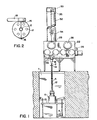
- FIG. 1 shows the system viewed from the front.
- a fuel cladding rod 2 to be loaded with fuel is held vertically upright by a fuel rod support clamp 4. Because of the length of the fuel rods 2, the rods 2 may be set in pit 1 in the building floor.
- the support clamp 4 is fixed to a vibrator 6 driven by vibrator motor 8.
- the vibrator 6 rests on a frame 10.
- the frame 10 is vertically adjustable to give the vibrator 6 a vertical travel of several feet. This allows the loading system to accommodate fuel cladding rods 2 of different lengths.
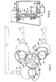
- the support clamp 4 is a cage structure of six vertical rods 12, three of which are held in a spaced parallel array by semi-circular pieces 14 (see Figure 2).
- the semi-circular pieces 14 are hinged at one end 16 and clamped 18 at the other. Only one of the bottom semi-circular pieces 14 of the support clamp 4 is fixed to the vibrator 6. This allows the half of the support clamp 4 whose bottom semi-circular piece 14 is not fixed to the vibrator 6 to swing open about the hinge 16 disclosing the interior of the clamp.
- This arrangement allows easy horizontal access to the interior of the fuel rod support clamp 4 in order to insert empty fuel cladding tubes 2 and remove loaded tube 2.
- the open upper end of the fuel cladding tube 2 is attached to an adaptor 18 with an airtight connection.
- the adaptor 18 is mounted to the glove box 22 via a bellows arrangement so that the fuel tube 2 is flexibly mounted to the glove box 22 allowing the fuel tube 2 to vibrate in response to the vibrator 6 while the tube is being loaded.
- the adaptor 18 is connected to the glove box 22 with a vacuum valve 24 so that the adaptor 18 and fuel tube 2 combination may be isolated from the clove box 22 formina an airtiaht combination.
- the glove box 22 is an enclosure capable of being made airtight which receives the nuclear fuel through the entrance vacuum valve 26.
- the glove box includes windows 28 and hinged glove box covers 30. Opening the glove box covers 30 reveals gloves (not shown) mounted to the glove box 22 which allows the operator to accomplish manipulation within the glove box 22 while still retaining the inert atmosphere within the glove box 22.
- On the upper side and connected to the glove box 22 is the rod loading assembly cover 32.
- the rod loading assembly cover 32 is of sufficient length to allow the rod loading assembly 34 to rise high enough so that it is free of the fuel cladding tube 2.
- Figure 3 shows a side view of the glove box and fuel cladding tube assembly.
- the fuel After entering the glove box through the vacuum valve 26, the fuel proceeds to the weighing station.
- Referring to figures 4, 5, 6, and 7 shows the passage of the spherical nuclear fuel from the entrance vacuum valve 26 to the loading hoppers 60 and 62 of the weighing stations.
- the nuclear fuel spheres enter the glove box 22 through the entrance vacuum valve 26 in containers 36 large enough to hold sufficient fuel for about six fuel tubes 2.
- the fuel containers 36 indicated by the dotted lines move along the rollers 40 of the transport conveyer 38, which may be powered or non-powered. After coming to rest on the conveyor 38, the fuel is lifted vertically upward by the overhead transport system 42.
- the overhead transport system 42 is capable of lifting the fuel container 36 from the transport conveyor 38 and moving it from right to left and back and forth within the glove box 22.
- the overhead transport conveyor 38 includes a rotating drum 41 around which is wrapped a cord 44 for raising and lowering the spheres.
- the containers 36 are moved one at a time from the transport conveyor 38 to the loading hoppers 60 and 62 of the weighing scales.
- three sizes of spheres are used,which are referred to herein as fines, mediums and large.
- the mediums weighing station 66 is shown in figure 4 by the dotted figure in the load position for receiving fuel.
- the fuel container 36 is attached to the transport lid 43 and moved by the overhead transport system 42 to each of the weighing stations where the fuel spheres are deposited into the hoppers 60 and 62 of the scales.
- the mediums 66 and large (not shown but designated 65 for convenience of reference) weighing stations are mounted on one platform and move from side to side by the drive motor 68.
- the weighing stations move up and down by the drive mechanism 72, the glove box 22 providing a recess 74 for the support shaft 76 when the station is lowered.
- the fines weighing station 64 moves front to back driven by the drive motor 78 within the glove box 22 as well as side to side motion driven by motor 70.
- Figure 7 shows a schematic view of the weighing station system viewed from above. The relative motion of the weighing stations, fines 64, mediums 66 and large 65 is indicated by arrows. The loading of the weighing station hoppers occurs when the stations are located at the position L of Figure 7.
- the mediums 66 and large 65 weighing stations are mounted on one platform and are moved to position L in Figure 7 for loading.
- the large (not shown but designated 61 for ronvenience of reference) and mediums 62 weighing stations loading hoppers are lowered to accommodate the fuel containers 36 which are moved to the weighing stations by the overhead fuel transport 42.
- the fines weighing system 64 is mounted independently of weighing stations 65 and 66 moves toward the back of the glove box 22, then to the right and down for loading.
- the fuel spheres containers 36 are picked up by the overhead transport system 42 and positioned on top of the weighing station hoppers. The spheres are released into the loading hoppers 60, 61 and 62 .
- Spheres of each size are dropped into the weighing scales hoppers 80 and 82 in incremental amounts by the stepper motors 84 and 86.
- the flow ceases (recall only two of the three weighing scales are shown in the Figures).
- These three predetermined amounts of the three sizes of fuel spheres are sufficient to fill one fuel rod 2 when they are mixed together within the fuel rod.
- These fuel spheres are then released into the hoppers 92, 94, and 96 of the feeding probe 34.
- the feeding probe 34 is described in more detail in copending application 82306517.0 based on U.S. 327,816.
- the probe is a means for feeding the three different sizes of spheres into the fuel rod 2 in a controlled manner so that the correct uniform density is achieved in the rod 2.
- the probe 34 includes three funnels 92, 94 and 96 into which each of the three quantities of fuel is discharged from the weighing scale hoppers 80, 81 and 82.
- only two 92 and 94 of the three funnels are shown for clarity.
- the funnels are spaced about 60 0 apart and are all identical except for the ability to accommodate different sized spherical fuel.
- the three funnels 92, 94 and 96 are connected to the probe hopper 98 via three solenoid valves 100. There is one solenoid valve 100 for each funnel.
- the probe hopper 98 is divided into three sections 102, 104 and 106 (see Figure 7).
- the gate 114 is releasably attached by conventional ball plunger means 115 to the hopper 98 so as to restrict the passageway 116 connecting the funnels 92 to the sections 102, 104 and 106 of the probe hopper 98.
- the gate 114 includes an opening of height h and width w.
- the probe hopper 98 is connected to tubing 108, 110 and 112. Each of these tubes corresponds to one of the sections of the probe hopper 98 which, in turn, corresponds to one of the funnels 92, 94 and 96.
- two of the tubes 108 and 110- are of the same circular cross-section. These tubes are used for the two smallest diameter fuel. The largest fuel sphere is carried by the tube 112 of larger cross section.
- each of the tubes 108, 110 and 112 may be extended into scoops as shown in Figure 8.
- the scoop shaped extensions terminate toward the axis through the center of the three tubed arrangement. These extensions help in the mixing of the fuel.spheres to provide a random distribution of packing of the fuel tube.
- a cone shaped piece 118 may be fixed to the lower end of the fuel tubes 108, 110 and 112 by two cylindrical rod members 130 as shown in Figure 8. The cone 118 is fixed to the rods 130 by conventional means.
- the method for using the above described system is described below. Some of operations described below are carried by the operator through the glove openings 28. Other operations are carried out automatically, e.g., the raising and lowering of the fuel probe 34.
- the operator places an empty fuel rod 2 in the fuel rod support clamp 4 fixed to the vibrator 6.
- the upper end of the rod 2 is connected to the adaptor 18 with a flexible coupling to the glove box 22.
- the feeding probe 34 which is attached to a raising and lowering means 33 by a cable 35 attached to bracket 31 is lowered into the fuel rod 2 so that the tubing 108, 110 and 112 reaches to the bottom of the fuel rod 2.
- the operator then transfers the fuel sphere container 36 from the transport conveyer 40 to the loading position L (See Figure 7) by the overhead transport system 42.
- the fuel spheres are transferred to the hoppers 60, 61 and 62 of the weighing scales. Predetermined amounts of fuel are released to the weighing station hoppers 80 and 82 by the stepper motors 84 and 86.
- the weighing stations are then moved into the dump position relative to the feed probe 34 so that the fuel spheres may be unloaded into the feeding probe hoppers.
- Figure 4 shows the mediums weighing station 66 in the loading position as indicated by the dotted outline. After loading the fuel into hopper 62, the weighing station is raised and moved into position as indicated by the solid figure to unload the fuel spheres into the fuel probe.
- Figures 5 and 6 show the fines weighing station 64 in the load position and the dump position, respectively.
- the weighing stations are moved out of the way of the fuel feeding probe 34 and the solenoid valves 100 are opened.
- the fuel spheres descend through the valve 100, the regulator gate 114 and the tubing 108, 110 and 112.
- the probe 34 is raised at a rate so that the bottom of the fuel probe 34 remains just above the ascending fuel column. That is, the spheres are deposited on top of the fuel column such that the end of the probe remains between about 1 and 5 in above the ascending fuel column.
- Copper tubes 132 guide the feeding probe 34 up and down.
- the copper tubes 132 in combination with wires 134 provide the electrical contact to operate the solenoids 100.
- the vibrator 6 is in operation while the fuel rod 2 is being loaded to assist in the packing of the fuel rod 2. After the loading is completed and feeding probe 90 is clear of the fuel rod 2, the rod is removed from the support clamp 4. A new fuel rod is placed in the clamp 4 and process is started again.
Landscapes
- Engineering & Computer Science (AREA)
- Physics & Mathematics (AREA)
- Manufacturing & Machinery (AREA)
- Plasma & Fusion (AREA)
- General Engineering & Computer Science (AREA)
- High Energy & Nuclear Physics (AREA)
- Monitoring And Testing Of Nuclear Reactors (AREA)
- Charge And Discharge Circuits For Batteries Or The Like (AREA)
- Elimination Of Static Electricity (AREA)
- Other Liquid Machine Or Engine Such As Wave Power Use (AREA)
Applications Claiming Priority (2)
| Application Number | Priority Date | Filing Date | Title |
|---|---|---|---|
| US06/327,817 US4495146A (en) | 1981-12-07 | 1981-12-07 | Spherical nuclear fuel loading system |
| US327817 | 1999-06-08 |
Publications (3)
| Publication Number | Publication Date |
|---|---|
| EP0081379A2 true EP0081379A2 (fr) | 1983-06-15 |
| EP0081379A3 EP0081379A3 (en) | 1984-11-07 |
| EP0081379B1 EP0081379B1 (fr) | 1988-04-13 |
Family
ID=23278197
Family Applications (1)
| Application Number | Title | Priority Date | Filing Date |
|---|---|---|---|
| EP82306518A Expired EP0081379B1 (fr) | 1981-12-07 | 1982-12-07 | Remplissage d'une barre combustible avec des sphères nucléaires |
Country Status (4)
| Country | Link |
|---|---|
| US (1) | US4495146A (fr) |
| EP (1) | EP0081379B1 (fr) |
| JP (1) | JPS58105096A (fr) |
| DE (1) | DE3278339D1 (fr) |
Cited By (2)
| Publication number | Priority date | Publication date | Assignee | Title |
|---|---|---|---|---|
| EP0081378A3 (en) * | 1981-12-07 | 1984-10-24 | Exxon Nuclear Company Inc. | Loading different-sized spheres of nuclear fuel into a fuel rod sheath |
| EP0449479A1 (fr) * | 1990-03-22 | 1991-10-02 | The Babcock & Wilcox Company | Dispositif mélangeur et de chargement de marériaux de densités différentes |
Families Citing this family (9)
| Publication number | Priority date | Publication date | Assignee | Title |
|---|---|---|---|---|
| US4748798A (en) * | 1985-05-10 | 1988-06-07 | Japan Nuclear Fuel Co., Ltd. | Apparatus for automatically loading nuclear fuel pellets |
| US4842808A (en) * | 1988-03-25 | 1989-06-27 | Westinghouse Electric Corp. | Nuclear fuel pellet collating system |
| US4897858A (en) * | 1988-03-25 | 1990-01-30 | Westinghouse Electric Corp. | Nuclear fuel pellet collating system and method |
| US20060176995A1 (en) * | 2005-02-10 | 2006-08-10 | Arizona Public Service Company | Control arrangement for use with nuclear fuel |
| JP4406465B2 (ja) * | 2008-03-27 | 2010-01-27 | 株式会社日本触媒 | 成型体用硬化性樹脂組成物、成型体及びその製造方法 |
| US10538001B2 (en) | 2011-03-16 | 2020-01-21 | Intech Defense, Llc | Methods and systems for providing protection against harmful materials |
| CN103578575B (zh) * | 2012-07-25 | 2016-08-31 | 李正蔚 | 球形燃料反应堆 |
| US11127508B2 (en) * | 2018-10-08 | 2021-09-21 | Bwxt Nuclear Energy, Inc. | Nuclear thermal propulsion fuel element packing device |
| CN113044321A (zh) * | 2019-12-27 | 2021-06-29 | 中核北方核燃料元件有限公司 | 一种核燃料元件连续自动包装装置及方法 |
Family Cites Families (18)
| Publication number | Priority date | Publication date | Assignee | Title |
|---|---|---|---|---|
| US2460605A (en) * | 1941-05-07 | 1949-02-01 | Certain Teed Prod Corp | Apparatus for feeding flowable material from a plurality of containers |
| GB548124A (en) * | 1941-06-24 | 1942-09-25 | Herbert Toms Ashton | Improvements relating to the manufacture of sheathed cores of pulverulent or powdered or comminuted material |
| US3947320A (en) * | 1953-04-01 | 1976-03-30 | The United States Of America As Represented By The United States Energy Research & Development Administration | Nickel container of highly-enriched uranium bodies and sodium |
| GB743424A (en) * | 1953-04-23 | 1956-01-18 | Keir & Cawder Ltd | Device and apparatus for controlled discharge of granular material |
| US2983658A (en) * | 1956-11-30 | 1961-05-09 | Herbert H Hyman | Heterogeneous nuclear reactor employing small unclad bodies of fissionable material as fuel |
| GB968759A (en) * | 1962-08-28 | 1964-09-02 | Atomic Energy Authority Uk | Nuclear reactor valve |
| GB1051954A (fr) * | 1964-04-08 | |||
| US3572405A (en) * | 1968-06-06 | 1971-03-23 | Atomic Energy Commission | Apparatus for blending particles |
| US3828518A (en) * | 1971-01-12 | 1974-08-13 | Babcock & Wilcox Co | Fuel rod fabrication |
| US3778348A (en) * | 1971-02-12 | 1973-12-11 | Atomic Energy Commission | Nuclear fuel element with axially aligned fuel pellets and fuel microspheres therein |
| US3838716A (en) * | 1973-07-24 | 1974-10-01 | Us Interior | System for packing particulate material into long cylindrical containers |
| DE2357426C2 (de) * | 1973-11-17 | 1984-07-19 | Hochtemperatur-Reaktorbau GmbH, 5000 Köln | Beschickungsanlage für Kernreaktoren mit kugelförmigen Betriebselementen |
| US3901409A (en) * | 1974-07-23 | 1975-08-26 | Us Energy | Apparatus for blending small particles |
| US4111335A (en) * | 1976-03-15 | 1978-09-05 | General Atomic Company | Metering system |
| DE2705763A1 (de) * | 1977-02-11 | 1978-08-17 | Rheinische Braunkohlenw Ag | Vorrichtung zum befuellen eines unter erhoehtem druck zu setzenden behaelters mit frei fliessenden feststoffen |
| JPS5458192A (en) * | 1977-10-19 | 1979-05-10 | Toshiba Corp | Insertng method into cladding tube of fuel pellets |
| US4312704A (en) * | 1979-04-30 | 1982-01-26 | Kernforschungsanlage Julich Gesellschaft Mit Beschrankter Haftung | Shut-off device blocking spontaneous passage of spherical bulk material especially in quick emptying pipes of pebble bed reactors |
| US4495145A (en) * | 1981-12-07 | 1985-01-22 | Exxon Nuclear Company, Inc. | Spherical nuclear fuel loading probe |
-
1981
- 1981-12-07 US US06/327,817 patent/US4495146A/en not_active Expired - Fee Related
-
1982
- 1982-12-07 JP JP57213455A patent/JPS58105096A/ja active Granted
- 1982-12-07 EP EP82306518A patent/EP0081379B1/fr not_active Expired
- 1982-12-07 DE DE8282306518T patent/DE3278339D1/de not_active Expired
Cited By (2)
| Publication number | Priority date | Publication date | Assignee | Title |
|---|---|---|---|---|
| EP0081378A3 (en) * | 1981-12-07 | 1984-10-24 | Exxon Nuclear Company Inc. | Loading different-sized spheres of nuclear fuel into a fuel rod sheath |
| EP0449479A1 (fr) * | 1990-03-22 | 1991-10-02 | The Babcock & Wilcox Company | Dispositif mélangeur et de chargement de marériaux de densités différentes |
Also Published As
| Publication number | Publication date |
|---|---|
| EP0081379B1 (fr) | 1988-04-13 |
| JPH0365519B2 (fr) | 1991-10-14 |
| JPS58105096A (ja) | 1983-06-22 |
| DE3278339D1 (en) | 1988-05-19 |
| US4495146A (en) | 1985-01-22 |
| EP0081379A3 (en) | 1984-11-07 |
Similar Documents
| Publication | Publication Date | Title |
|---|---|---|
| US4495146A (en) | Spherical nuclear fuel loading system | |
| US5897282A (en) | Catalytic reactor charging system and method for operation thereof | |
| US20010041117A1 (en) | Catalytic reactor charging system and method for operation thereof | |
| EP0081378B1 (fr) | Remplissage d'une gaine de barreau combustible avec des sphères nucléaires de dimensions diverses | |
| RU2180265C1 (ru) | Способ и устройство для загрузки частиц в трубу трубчатого реактора | |
| US6319118B1 (en) | Seed package handling system for test plot combine | |
| JPH07330163A (ja) | 物質処理装置 | |
| US4332120A (en) | Nuclear fuel pellet loading apparatus | |
| WO1998014392A1 (fr) | Systeme et procede de chargement d'un reacteur catalytique | |
| WO1998002238A1 (fr) | Mecanisme de remplissage d'un reacteur a tubes | |
| CN218621125U (zh) | 一种单晶炉用加料器自动加料系统 | |
| CN219044422U (zh) | 一种用于小口容器的粉末装填机 | |
| JP6435436B2 (ja) | 錠剤処理設備 | |
| JPH07315302A (ja) | 粉体の定量充填装置およびこれに用いる弁 | |
| GB2571823A (en) | Pinch valve | |
| CN107695331B (zh) | 一种用于塞棒生产的自动装料系统 | |
| EP4663563A1 (fr) | Agencement de dispositif de décharge de sacs | |
| JPH0117406B2 (fr) | ||
| CN217754352U (zh) | 粒状物体自动装填机构 | |
| EP0013166A1 (fr) | Tube vibratoire d'alimentation pour système de transfert de poudre | |
| EP0449479A1 (fr) | Dispositif mélangeur et de chargement de marériaux de densités différentes | |
| JP4097990B2 (ja) | 選別乾燥充填装置及びそれに用いられるカプセル支持装置 | |
| CN218877640U (zh) | 一种粉末涂料装料传输装置 | |
| US4954036A (en) | Variable height silo charge system | |
| US3913637A (en) | Revolving bagging machine |
Legal Events
| Date | Code | Title | Description |
|---|---|---|---|
| PUAI | Public reference made under article 153(3) epc to a published international application that has entered the european phase |
Free format text: ORIGINAL CODE: 0009012 |
|
| AK | Designated contracting states |
Designated state(s): BE CH DE FR GB LI SE |
|
| PUAL | Search report despatched |
Free format text: ORIGINAL CODE: 0009013 |
|
| AK | Designated contracting states |
Designated state(s): BE CH DE FR GB LI SE |
|
| 17P | Request for examination filed |
Effective date: 19850416 |
|
| 17Q | First examination report despatched |
Effective date: 19860526 |
|
| RAP1 | Party data changed (applicant data changed or rights of an application transferred) |
Owner name: SIEMENS AKTIENGESELLSCHAFT BERLIN UND MUENCHEN |
|
| GRAA | (expected) grant |
Free format text: ORIGINAL CODE: 0009210 |
|
| AK | Designated contracting states |
Kind code of ref document: B1 Designated state(s): BE CH DE FR GB LI SE |
|
| REF | Corresponds to: |
Ref document number: 3278339 Country of ref document: DE Date of ref document: 19880519 |
|
| ET | Fr: translation filed | ||
| PLBE | No opposition filed within time limit |
Free format text: ORIGINAL CODE: 0009261 |
|
| STAA | Information on the status of an ep patent application or granted ep patent |
Free format text: STATUS: NO OPPOSITION FILED WITHIN TIME LIMIT |
|
| 26N | No opposition filed | ||
| PGFP | Annual fee paid to national office [announced via postgrant information from national office to epo] |
Ref country code: GB Payment date: 19901116 Year of fee payment: 9 |
|
| PGFP | Annual fee paid to national office [announced via postgrant information from national office to epo] |
Ref country code: SE Payment date: 19901212 Year of fee payment: 9 |
|
| PGFP | Annual fee paid to national office [announced via postgrant information from national office to epo] |
Ref country code: FR Payment date: 19901219 Year of fee payment: 9 |
|
| PGFP | Annual fee paid to national office [announced via postgrant information from national office to epo] |
Ref country code: BE Payment date: 19901228 Year of fee payment: 9 |
|
| PGFP | Annual fee paid to national office [announced via postgrant information from national office to epo] |
Ref country code: DE Payment date: 19910225 Year of fee payment: 9 |
|
| PGFP | Annual fee paid to national office [announced via postgrant information from national office to epo] |
Ref country code: CH Payment date: 19910322 Year of fee payment: 9 |
|
| PG25 | Lapsed in a contracting state [announced via postgrant information from national office to epo] |
Ref country code: GB Effective date: 19911207 |
|
| PG25 | Lapsed in a contracting state [announced via postgrant information from national office to epo] |
Ref country code: SE Effective date: 19911208 |
|
| PG25 | Lapsed in a contracting state [announced via postgrant information from national office to epo] |
Ref country code: LI Effective date: 19911231 Ref country code: CH Effective date: 19911231 Ref country code: BE Effective date: 19911231 |
|
| BERE | Be: lapsed |
Owner name: SIEMENS A.G. BERLIN UND MUNCHEN Effective date: 19911231 |
|
| GBPC | Gb: european patent ceased through non-payment of renewal fee | ||
| PG25 | Lapsed in a contracting state [announced via postgrant information from national office to epo] |
Ref country code: FR Effective date: 19920831 |
|
| REG | Reference to a national code |
Ref country code: CH Ref legal event code: PL |
|
| PG25 | Lapsed in a contracting state [announced via postgrant information from national office to epo] |
Ref country code: DE Effective date: 19920901 |
|
| REG | Reference to a national code |
Ref country code: FR Ref legal event code: ST |
|
| EUG | Se: european patent has lapsed |
Ref document number: 82306518.0 Effective date: 19920704 |