EP0082041A1 - Procédé et dispositif pour commander la respiration artificielle - Google Patents
Procédé et dispositif pour commander la respiration artificielle Download PDFInfo
- Publication number
- EP0082041A1 EP0082041A1 EP82402173A EP82402173A EP0082041A1 EP 0082041 A1 EP0082041 A1 EP 0082041A1 EP 82402173 A EP82402173 A EP 82402173A EP 82402173 A EP82402173 A EP 82402173A EP 0082041 A1 EP0082041 A1 EP 0082041A1
- Authority
- EP
- European Patent Office
- Prior art keywords
- ventilation
- fco
- controlled
- state
- patient
- Prior art date
- Legal status (The legal status is an assumption and is not a legal conclusion. Google has not performed a legal analysis and makes no representation as to the accuracy of the status listed.)
- Withdrawn
Links
- 238000000034 method Methods 0.000 title claims description 7
- 230000029058 respiratory gaseous exchange Effects 0.000 claims abstract description 6
- 239000000523 sample Substances 0.000 claims abstract description 3
- 238000002627 tracheal intubation Methods 0.000 claims abstract description 3
- 238000009423 ventilation Methods 0.000 claims description 58
- 230000002269 spontaneous effect Effects 0.000 claims description 24
- 230000001131 transforming effect Effects 0.000 claims 1
- 239000007789 gas Substances 0.000 description 9
- 235000021183 entrée Nutrition 0.000 description 5
- 239000008280 blood Substances 0.000 description 4
- 210000004369 blood Anatomy 0.000 description 4
- 238000010586 diagram Methods 0.000 description 4
- 230000003519 ventilatory effect Effects 0.000 description 4
- 230000004913 activation Effects 0.000 description 3
- 208000008784 apnea Diseases 0.000 description 3
- 238000013125 spirometry Methods 0.000 description 3
- CURLTUGMZLYLDI-UHFFFAOYSA-N Carbon dioxide Chemical compound O=C=O CURLTUGMZLYLDI-UHFFFAOYSA-N 0.000 description 2
- 240000008042 Zea mays Species 0.000 description 2
- 229910002092 carbon dioxide Inorganic materials 0.000 description 2
- 230000008859 change Effects 0.000 description 2
- 238000001514 detection method Methods 0.000 description 2
- 230000006872 improvement Effects 0.000 description 2
- 239000000203 mixture Substances 0.000 description 2
- 238000012544 monitoring process Methods 0.000 description 2
- 230000000750 progressive effect Effects 0.000 description 2
- 230000001360 synchronised effect Effects 0.000 description 2
- 230000007704 transition Effects 0.000 description 2
- 238000012935 Averaging Methods 0.000 description 1
- 206010009192 Circulatory collapse Diseases 0.000 description 1
- 208000010496 Heart Arrest Diseases 0.000 description 1
- 241000287107 Passer Species 0.000 description 1
- 208000001871 Tachycardia Diseases 0.000 description 1
- 230000009471 action Effects 0.000 description 1
- 230000001154 acute effect Effects 0.000 description 1
- 206010001053 acute respiratory failure Diseases 0.000 description 1
- 230000006978 adaptation Effects 0.000 description 1
- QVGXLLKOCUKJST-UHFFFAOYSA-N atomic oxygen Chemical compound [O] QVGXLLKOCUKJST-UHFFFAOYSA-N 0.000 description 1
- 230000008901 benefit Effects 0.000 description 1
- 239000001569 carbon dioxide Substances 0.000 description 1
- 230000002425 cardiocirculatory effect Effects 0.000 description 1
- 230000007423 decrease Effects 0.000 description 1
- 230000001934 delay Effects 0.000 description 1
- 230000000694 effects Effects 0.000 description 1
- 230000014509 gene expression Effects 0.000 description 1
- 230000002045 lasting effect Effects 0.000 description 1
- 230000000474 nursing effect Effects 0.000 description 1
- 229910052760 oxygen Inorganic materials 0.000 description 1
- 239000001301 oxygen Substances 0.000 description 1
- 230000000241 respiratory effect Effects 0.000 description 1
- 201000004193 respiratory failure Diseases 0.000 description 1
- 206010040560 shock Diseases 0.000 description 1
- 239000000725 suspension Substances 0.000 description 1
- 230000006794 tachycardia Effects 0.000 description 1
- 230000001960 triggered effect Effects 0.000 description 1
- 230000002747 voluntary effect Effects 0.000 description 1
- XLYOFNOQVPJJNP-UHFFFAOYSA-N water Chemical compound O XLYOFNOQVPJJNP-UHFFFAOYSA-N 0.000 description 1
Images



Classifications
-
- G—PHYSICS
- G01—MEASURING; TESTING
- G01N—INVESTIGATING OR ANALYSING MATERIALS BY DETERMINING THEIR CHEMICAL OR PHYSICAL PROPERTIES
- G01N33/00—Investigating or analysing materials by specific methods not covered by groups G01N1/00 - G01N31/00
- G01N33/48—Biological material, e.g. blood, urine; Haemocytometers
- G01N33/483—Physical analysis of biological material
- G01N33/497—Physical analysis of biological material of gaseous biological material, e.g. breath
-
- A—HUMAN NECESSITIES
- A61—MEDICAL OR VETERINARY SCIENCE; HYGIENE
- A61M—DEVICES FOR INTRODUCING MEDIA INTO, OR ONTO, THE BODY; DEVICES FOR TRANSDUCING BODY MEDIA OR FOR TAKING MEDIA FROM THE BODY; DEVICES FOR PRODUCING OR ENDING SLEEP OR STUPOR
- A61M16/00—Devices for influencing the respiratory system of patients by gas treatment, e.g. ventilators; Tracheal tubes
- A61M16/0051—Devices for influencing the respiratory system of patients by gas treatment, e.g. ventilators; Tracheal tubes with alarm devices
-
- A—HUMAN NECESSITIES
- A61—MEDICAL OR VETERINARY SCIENCE; HYGIENE
- A61M—DEVICES FOR INTRODUCING MEDIA INTO, OR ONTO, THE BODY; DEVICES FOR TRANSDUCING BODY MEDIA OR FOR TAKING MEDIA FROM THE BODY; DEVICES FOR PRODUCING OR ENDING SLEEP OR STUPOR
- A61M16/00—Devices for influencing the respiratory system of patients by gas treatment, e.g. ventilators; Tracheal tubes
- A61M16/021—Devices for influencing the respiratory system of patients by gas treatment, e.g. ventilators; Tracheal tubes operated by electrical means
- A61M16/022—Control means therefor
- A61M16/024—Control means therefor including calculation means, e.g. using a processor
-
- A—HUMAN NECESSITIES
- A61—MEDICAL OR VETERINARY SCIENCE; HYGIENE
- A61M—DEVICES FOR INTRODUCING MEDIA INTO, OR ONTO, THE BODY; DEVICES FOR TRANSDUCING BODY MEDIA OR FOR TAKING MEDIA FROM THE BODY; DEVICES FOR PRODUCING OR ENDING SLEEP OR STUPOR
- A61M16/00—Devices for influencing the respiratory system of patients by gas treatment, e.g. ventilators; Tracheal tubes
- A61M16/04—Tracheal tubes
- A61M16/0402—Special features for tracheal tubes not otherwise provided for
- A61M16/0411—Special features for tracheal tubes not otherwise provided for with means for differentiating between oesophageal and tracheal intubation
- A61M2016/0413—Special features for tracheal tubes not otherwise provided for with means for differentiating between oesophageal and tracheal intubation with detectors of CO2 in exhaled gases
-
- A—HUMAN NECESSITIES
- A61—MEDICAL OR VETERINARY SCIENCE; HYGIENE
- A61M—DEVICES FOR INTRODUCING MEDIA INTO, OR ONTO, THE BODY; DEVICES FOR TRANSDUCING BODY MEDIA OR FOR TAKING MEDIA FROM THE BODY; DEVICES FOR PRODUCING OR ENDING SLEEP OR STUPOR
- A61M2230/00—Measuring parameters of the user
- A61M2230/40—Respiratory characteristics
- A61M2230/43—Composition of exhalation
- A61M2230/432—Composition of exhalation partial CO2 pressure (P-CO2)
Definitions
- the subject of the present invention is an improvement in ventilators or artificial ventilators and more particularly a new apparatus intended to facilitate the weaning of patients subjected to ventilatory assistance and the monitoring of spontaneous ventilation modes (VS-CPAP IMV). It also aims at a new operating mode for controlling artificial respiration.
- ventilation is controlled by the carbon dioxide content of the gas exhaled by the patient.
- a cell for analyzing the CO 2 content of the exhaled gas is added to an artificial respirator, a capnograph, an apparatus which receives the CO 2 content from the cell and transforms it into an analog electrical signal, and an on-demand ventilation module controlled by the C0 2 content, device which receives the analog signal from the capnigrapher and which controls the running of the fan.
- the cell and the capnigrapher are known devices, available commercially.
- the module is new and constitutes an important characteristic of the present invention.
- the system according to the invention which thus comprises a method and a device, takes into account the respiratory efficiency of the patient and allows weaning under conditions of maximum safety, for the minimum intervention of the nursing staff.
- bistable elements which can take two states: a low state, or zero and a high state or one. We will use to simplify the expressions zero and one without assigning a limiting character to it.
- a device comprises a ventilator, or artificial respirator 1, which can be of any type, connected to a patient by means of an intubation probe, tracheostomy , or less often a mask 2, supplied by an inspiration conduit 3 and an exhalation conduit 4.
- a cell 6 for analyzing C0 2 is placed on the dead space of apparatus (part of the circuit swept alternately by the inspired gas and by the exhaled gas)
- a cell 6 for analyzing C0 2 connected by a line 7 to a capnigraph 8.
- This is connected by a line 9 to input A of the module 11 for ventilation on demand (MVC0 2 , of after the name in English Mandatory Ventilation), whose output B is connected by a line 12 to the fan 1.
- the device can be adapted to all modern fans, having a spontaneous mode of operation.
- the capnigraphy is collected at the level of the apparatus dead space (figure 1).
- FIG. 2 represents the analog output signal from the capnograph. During inspiration, the C0 2 concentration is zero. Each tooth on the curve represents an expiration period: the concentration is maximum at the end of expiration.
- the doctor determines two monitoring ranges; the first between a minimum and maximum threshold: this is range 1 (FI) -figure 2- called spontaneous ventilation; the second between the same minimum threshold and an intermediate threshold lower than the maximum threshold, it is the range n ° 2 (F2), called controlled ventilation.
- the maximum threshold (FCO 2 max) is calculated by the difference between PCO 2ET (partial pressure of CO 2 expired at the end of expiration) and the partial pressure of CO 2 in arterial blood (PaC0 2 ).
- This gradient is a characteristic of the patient at the time of weaning. (Weaning is the period of removal of the ventilator from the time the patient has acceptable independent breathing). It requires an analysis of arterial blood gases for its determination.
- PB is the barometric pressure
- PBH 2 0 is the partial pressure of water vapor
- ECO 2ET the CO 2 concentration of the gas exhaled at the end of expiration
- PCO 2ET the partial pressure of CO 2 of the gas exhaled at the end of expiration
- PaCO 2 the partial pressure of CO 2 in the blood.
- the maximum FCO 2 max threshold will be set at 4.5%.
- the minimum threshold (FCO 2 min) is always greater than 1% CO 2 . It allows the resumption of control by the ventilator in the event of apnea, acute cardio-circulatory failure, cardiac arrest or very significant tachycardia.
- the intermediate threshold (FC0 2 int) is always between FCO 2 max and FCO 2 min.
- FCO 2ET In the controlled ventilation mode, FCO 2ET must be between FCO 2 min and FC0 2 int.
- the patient When the system is started, the patient is in controlled ventilation and the values of FCO 2 min and FC0 2 int are determined; then the patient is put into spontaneous ventilation and FCO 2 max is determined.
- the device automatically engages the "controlled ventilation" mode, if the overshoot is constant and lasting more than one period whose variable duration can be fixed for example at 15 or 20 s (time delay T1).
- controlled ventilation FCO 2ET decreases rapidly and must again be between FCO 2 min and FCO 2 int.
- T2 time delay
- any failure of the capnograph, any absence of power to the system also triggers the controlled mode, as well as the voluntary shutdown of the device, or by default of power.
- the device has a standby control 56, Figure 3, which suspends its operation during aspirations and patient care.
- the controlled ventilation mode is then adopted. Stopping from the "stand by" position restarts the system in the mode it was in before the suspension.
- FIG. 3 represents the block diagram of the module 11 of FIG. 1.
- the CO 2 signal coming from the capnigraph 8 is delivered at point A.
- a concentration of 1% of C0 2 can be represented by a voltage of 1 volt.
- the module includes a power supply 25 with a sector fault detector 26, and a manual control 27. It is advantageously possible to provide a display 28 of the CO 2 content.
- the module has three threshold detectors: a maximum threshold detector D1, a minimum threshold detector D2 and an intermediate threshold detector D3. In one embodiment of the invention, these detectors can be flip-flops which take on their outputs the state zero when the voltage at the input is higher than the chosen voltage, and the state one, when the voltage of entry is lower.
- the output B of the module is connected to the connection 51 to the ventilator, connected through the memory 49 (memorization of the state of the ventilator) to the control lever 35, 36: 35 activation of the ventilator, 36 activation stop the respirator. Only the zero states cause the position of the flip-flop 35, 36 to change.
- Manual control 27 is connected to input 31 of door 37. If the three inputs 31, 32, 33 of door 37 are in state one, output 38 is in state one, which doesn’t has no action on starting. If one of the inputs 31, 32, 33 is in the zero state, the output 38 is the zero state, which triggers the start-up of the ventilator.
- T1 goes to zero state (exceeding FCO 2 max) T1 takes state one for (for example) 15 s.
- D2 goes to zero state (exceeding FCO 2 min) T2 takes state one for 15 s.
- T2 goes to state zero which triggers start-up (as soon as one of the inputs 31 , 32, 33 is at state zero), which triggers the audible alarm 50, through memory 49.
- the activation of the respirator triggers by line 40 an impulse which puts T3 in state one for one 5 min series (for example).
- the zero state of D3 (exceeding FC0 2 int) keeps T3 in state one for 5 minutes each time. If for 5 min T3 does not receive anything from D3 (no overshoot of FCO 2 int, D3 remains at state one) T3 goes to zero state, which controls the stopping 36 of the respirator.
- D1 is connected to the reset of B1 by line 44
- Tl is connected to the input D of Bl, whose command C is connected by line 41 to the output of D2.
- the output S of B1 is connected to the input D of B2, the control C of which is connected by line 42 also to the output of D2.
- the reset to one of B2 is connected by line 43 to the automatic reset 45.
- the output S of B2 is connected to the input D of B3, the control C of which is connected by line 46 of T1.
- the reset to one of B3 is connected by line 47 to the output S of B2, line 47 being also connected to the reset to T1.
- the output S of B3 is connected to the input 32 of gate 37.
- the scales are set as follows.
- a zero state of D2 through line 41 causes the state of D. to go to S.
- a state one of D2 through line 42 causes the state of D. to go to S.
- Tl sends a pulse on command C at the end of the 15 s time delay period of T1. This pulse changes the state of D.
- the module works as follows.
- T2 If after 15s T2 has not received a pulse on its input from D2, it goes to zero and the ventilator starts to operate; from the moment it starts, T3 receives a pulse and delays for a time set for example at 5 min.
- the state of the respirator is stored in memory 49 and is restored when the sector returns or when the standby button is released.
- FIG. 4 represents an example of practical assembly with the conventional signs and the values of the components. Those skilled in the art can thus completely realize the device of the invention. It is obvious that variants or equivalents are possible, both in the detail of the assembly and the choice of components or their values.
- FIG. 5 represents the evolution of the CO 2 content of the gas exhaled during one day.
- VC stands for controlled ventilation and VS for spontaneous ventilation.
- the device has the advantage of maintaining a constant PaCO 2 at during the day.
- FIG. 2 represents a sequence of spontaneous ventilation, until the end F1 of T1, controlled ventilation until the end F2 of T2, then spontaneous ventilation again.
- microprocessor will allow an earlier detection of the value of FC0 2ET and an averaging over three cycles, to fix more precisely the values of the different thresholds, to fix variable durations according to the patients for T1 and T2, and especially to consider between the controlled ventilation mode and the spontaneous mode, a transition to intermittent ventilation on demand (IMV) progressively degraded.
- IMV intermittent ventilation on demand
- FIG. 6 represents a progressive withdrawal period with passage into IMV mode: intermittent forced ventilation. There is a spontaneous ventilation until the end F1 of T1, a controlled ventilation until the end F2 of T2 then an IMV ventilation until F3 and then a spontaneous ventilation.
- the time T3 duration of each of the IMV types (2/1, 3/1, 4/1, etc.) can be fixed, of the order of 3 min, or variable, adjustable by the doctor for each patient.
- a mircoprocessor could also per to take into account the ventilatory frequency in the spontaneous mode; exceeding a maximum and minimum threshold causing the respirator to start in the controlled mode. This consideration of the ventilatory frequency is a possible improvement of the system.
Landscapes
- Health & Medical Sciences (AREA)
- Life Sciences & Earth Sciences (AREA)
- Engineering & Computer Science (AREA)
- Biomedical Technology (AREA)
- Hematology (AREA)
- General Health & Medical Sciences (AREA)
- Physics & Mathematics (AREA)
- Chemical & Material Sciences (AREA)
- Anesthesiology (AREA)
- Animal Behavior & Ethology (AREA)
- Pulmonology (AREA)
- Public Health (AREA)
- Veterinary Medicine (AREA)
- Molecular Biology (AREA)
- Emergency Medicine (AREA)
- Heart & Thoracic Surgery (AREA)
- Urology & Nephrology (AREA)
- Biophysics (AREA)
- Food Science & Technology (AREA)
- Medicinal Chemistry (AREA)
- Analytical Chemistry (AREA)
- Biochemistry (AREA)
- General Physics & Mathematics (AREA)
- Immunology (AREA)
- Pathology (AREA)
- Measurement Of The Respiration, Hearing Ability, Form, And Blood Characteristics Of Living Organisms (AREA)
- Percussion Or Vibration Massage (AREA)
- Respiratory Apparatuses And Protective Means (AREA)
Abstract
La mise à l'arrêt ou en marche du respirateur (1) est commandée par un module (11) recevant d'un capnigraphe (8) un signal électrique représentatif de la teneur en CO2 du gaz traversant une cellule (6) d'analyse du CO2 fixée à la sortie de la sonde d'intubation, de trachéotomie d'un patient en respiration assistée. C'est la teneur en CO2 qui détermine la marche ou l'arrêt de l'assistance par le respirateur.
Description
- La présente invention a pour objet un perfectionnement aux respirateurs ou ventilateurs artificiels et plus particulièrement un nouvel appareillage destiné à faciliter le sevrage des malades soumis à l'assistance ventilatoire et la surveillance des modes de ventilation spontanée (VS-CPAP IMV). Elle vise également un nouveau mode opératoire de commande de la respiration artificielle.
- Il existe actuellement des systèmes permettant la ventilation à la demande au cours du sevrage des malades soumis à l'assistance ventilatoire pour un épisode d'insuffisance respiratoire aiguë. Parmi ces systèmes on connait notamment :
- - la mise en ventilation spontanée avec utilisation du respirateur qui délivre au malade un mélange gazeux, à concentration en oxygène, température et humidification constantes. La spirométrie peut être surveillée. En cas d'apnée (absence de respiration) le ventilateur reprend la commande après un délai constant. L'adjonction d'une pression positive résiduelle est possible ; elle est dénommée couramment CPAP, d'après l'appellation en anglais : Continuous Positive Airway Pressure.
- - l'utilisation du Trigger ou ventilation auto-déclenchée, le malade maitrisant la fréquence de fonctionnement du respirateur.
- - la ventilation intermittente à la demande qui permet une assistance ventilatoire partielle à raison de n cycles spontanés pour 1 cycle controlé (2/1, 3/1, 4/1, etc). Ce système peut fonctionner sur un mode synchrone ou non synchrone. Il est désigné couramment IMV, d'après l'appellation en anglais : Intermittent Mandatory Ventilation.
- - la ventilation forcée déterminée dans laquelle est définie une spirométrie de base que le malade doit dépasser en ventilation spontanée. Si la spirométrie spontanée du malade est inférieure à une limite que le médecin peut fixer, le ventilateur reprend la commande. Ce système est désigné habituellement par MMV, également d'après l'appellation en anglais : Minute Mandatory Ventilation.
- Aucun de ces systèmes n'est pleinement satisfaisante En effet, aucun d'entre eux ne tient compte de l'efficacité de la ventilation spontanée du malade.
- Conformément à la présente invention, la ventilation est asservie à la teneur en gaz carbonique du gaz expiré par le patient. Selon la présente invention, on adjoint à un respirateur artificiel une cellule d'analyse de la teneur en C02 du gaz expiré, un capnigraphe, appareil qui reçoit de la cellule la teneur en CO2 et la transforme en un signal électrique analogique, et un module de ventilation à la demande asservi à la teneur en C02, appareil qui reçoit le signal analogique du capnigraphe et qui commande la marche du ventilateur.
- La cellule et le capnigraphe sont des appareils connus, disponibles dans le commerce. Le module est nouveau et constitue une caractéristique importante de la présente invention.
- Le système selon l'invention, qui comporte ainsi un procédé et un dispositif, tient compte de l'efficacité respiratoire du malade et permet le sevrage dans des conditions desé- curité maximum, pour le minimum d'intervention du personnel soignant.
- D'autres caractéristiques de l'invention apparaîtront au cours de la description qui va suivre, donnée à titre d'exemple non limitatif en regard des dessins ci-joints, et qui fera bien comprendre comment l'invention peut être réalisée.
- Les dessins montrent :
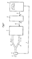
- - figure 1 : un schéma général du dispositif selon l'invention ;
- - figure 2 : une représentation d'un signal analogue délivré par capnigraphe ;
- - figure 3 : un schéma bloc du module selon l'invention
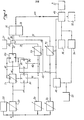
- - figure 4 : un schéma complet avec indication des composants du module de la figure 3;
- - figure 5 : une représentation de l'évolution de la pression partielle de C02 dans le sang (PaC02) au cours d'une journée, avec utilisation du dispositif selon l'invention ; et
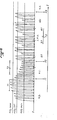
- - figure 6 : une représentation du signal de sortie du capnigraphe au cours d'une séquence de sevrage progressif avec passage en mode à ventilation intermittente (IMV).
- Dans la suite de la description, on décrira l'emploi d'éléments bistables qui peuvent prendre deux états : un état bas, ou zéro et un état haut ou un. On utilisera pour simplifier les expressions zéro et un sans y attribuer un caractère limitatif.
- Comme on peut le voir sur la figure 1, un dispositif selon l'invention comporte un ventilateur, ou respirateur artificiel 1, qui peut être d'un type quelconque, branché sur un patient au moyen d'une sonde d'intubation, de trachéotomie, ou moins souvent d'un masque 2, alimenté par un conduit d'inspiration 3 et un conduit d'expiration 4. Sur l'espace mort d'appareillage (partie du circuit balayée alternativement par le gaz inspiré et par le gaz expiré) est placée une cellule 6 d'analyse du C02, connectée par une ligne 7 à un capnigraphe 8. Celui-ci est connecté par une ligne 9 à l'entrée A du module 11 de ventilation à la demande (M.V.C02, d'après l'appellation en langue anglaise Mandatory Ventilation), dont la sortie B est connectée par une ligne 12 au ventilateur 1.
- L'appareil peut s'adapter à tous les ventilateurs modernes, possédant un mode de fonctionnement spontané. La capnigra- phie est recueillie au niveau de l'espace mort d'appareillage (figure 1). La concentration maxima (en fin d'expiration) de CO2 expiré par le malade (FCO2ET ; ET = End Tidal ou fin de cycle) est la valeur constamment surveillée.
- La figure 2 représente le signal analogique de sortie du capnigraphe. Pendant l'inspiration, la concentration en C02 est nulle. Chaque dent de la courbe représente une période d'expiration : la concentration est maximum en fin d'expiration.
- Le médecin détermine deux fourchettes de surveillance ; la première entre un seuil minimum et maximum : c'est la fourchette n° 1 (FI) -figure 2- dite de ventilation spontanée ; la seconde entre le même seuil minimum et un seuil intermédiaire inférieur au seuil maximum, c'est la fourchette n° 2 (F2), dite de ventilation contrôlée.
- Le seuil maximum (FCO2max) est calculé par la différence entre PCO2ET (pression partielle du CO2 expiré de fin d'expiration) et la pression partielle de CO2 dans le sang artériel (PaC02). Ce gradient est une caractéristique du malade au moment du sevrage. (Le sevrage est la période d'enlèvement du ventilateur à partir du moment où le patient a une respiration autonome acceptable). Il nécessite une analyse des gaz du sang artériel pour sa détermination.


- Par exemple, si l'on désire que la PaCO2 du malade ne dépasse pas 45 mmHg, pour un gradient de 12 mmHg :



- Le seuil maximum de FCO2max sera fixé à 4,5%.
- Le seuil minimum (FCO2min) est toujours supérieur à 1% de CO2. Il permet la reprise de la commande par le ventilateur en cas d'apnée, de défaillance cardio-circulatoire aiguë, d'arrêt cardiaque ou de tachycardie très importante.
- Le seuil intermédiaire (FC02int) est toujours compris entre le FCO2max et FCO2min. Il est nécessaire que, dans le mode de ventilation contrôlée, FCO2ET soit compris entre FCO2min et FC02int.
- A la mise en route du système, le malade est en ventilation contrôlée et les valeurs de FCO2min et de FC02int sont déterminées ; puis le malade est mis en ventilation spontanée et FCO2max est déterminée.
- Tant que le malade présente une ventilation satisfaisante avec


- Si FCO2ET reste effectivement compris entre ces deux seuils pendant une période pouvant être fixée par exemple à 5 mn (temps de temporisation T2), l'appareil enclenche alors le mode de ventilation spontanée. Tl et T2 sont réglables dans leur durée de façon interne à l'appareil. Entre la fin de T1 et la fin de T2 (figure 2) la ventilation est contrôlée, en dehors de cette période, elle est spontanée
- Toute absence de cycle, apnée en inspiration ou en expiration, enclenche automatiquement le mode de ventilation contrôlée après un temps égal à T1.
- Toute panne du capnigraphe, toute absence d'alimentation du système enclenche également le mode contrôlé, de même que l'arrêt volontaire de l'appareil, ou par défaut d'alimentation.
- L'appareil dispose d'une commande mise en attente (stand by) 56, figure 3, qui suspend son fonctionnement durant les aspirations et soins du malade. Le mode ventilation contrôlée est alors adopté. L'arrêt de la position "stand by" fait redémarrer le système dans le mode qui était le sien avant la suspension.
- La figure 3 représente le schéma de principe du module 11 de la figure 1. Le signal CO2 provenant du capnigraphe 8 est délivré au point A. A titre d'exemple commode, une concentration de 1% de C02 peut être représentée par une tension de 1 volt. Le module comporte une alimentation 25 avec un détecteur de pannes secteur 26, et une commande manuelle 27. On peut avantageusement prévoir un affichage 28 de la teneur en C02. Le modulé comporte trois détecteurs de seuil : un détecteur de seuil maxi Dl, un détecteur de seuil mini D2 et un détecteur de seuil intermédiaire D3. Dans une forme de réalisation de l'invention, ces détecteurs peuvent être des bascules qui prennent sur leurs sorties l'état zéro quand la tension à l'entrée est supérieure à la tension choisie, et l'état un, quand la tension d'entrée est inférieure.
- La sortie B du module est branchée sur la connexion 51 au respirateur, reliée à travers la mémoire 49 (mise en mémorisation de l'état du respirateur) à la bascule de commande 35, 36 : 35 mise en marche du respirateur, 36 mise à l'arrêt du respirateur. Seuls les états zéro font changer la position de la bascule 35, 36.
- Les détecteurs Dl, D2, D3 sont connectés chacun à une temporisation T1, T2, T3.
- T1 est connecté, à travers une bascule B3 à l'entrée 32 d'une porte ET 37 dont la sortie 38 est connectée à la mise en marche 35 ;
- T2 est connecté à l'entrée 33 de la porte 37 et
- T3 est connecté par la ligne 39 à la mise à l'arrêt 36.
- La commande manuelle 27 est connectée à l'entrée 31 de la porte 37. Si les trois entrées 31, 32, 33 de la porte 37 sont à l'état un, la sortie 38 est à l'état un, ce qui n'a pas d'action sur la mise en marche. Si une des entrées 31, 32, 33 est à l'état zéro, la sortie 38 est l'état zéro, ce qui déclenche la mise en marche 35 du respirateur. Quand D1 passe à l'état zéro (dépassement de FCO2max) T1 prend l'état un pour (par exemple) 15 s. Quand D2 passe à l'état zéro (dépassement de FCO2min) T2 prend l'état un pour 15 s. Si D2 garde l'état un, c'est-à-dire si FCO2min n'est pas atteint pendant 15 s, T2 passe à l'état zéro ce qui déclenche la mise en marche (dès qu'une des entrées 31, 32, 33 est à l'état zéro), ce qui déclenche l'alarme sonore 50, à travers la mémoire 49. La mise en marche du respirateur déclenche par la ligne 40 une impulsion qui met T3 à l'état un pour une série de 5 mn (par exemple). L'état zéro de D3 (dépassement de FC02int) maintient chaque fois T3 à l'état un pour 5 mn. Si pendant 5 mn T3 ne reçoit rien de D3 (pas de dépassement de FCO2int, D3 reste à l'état un) T3 passe à l'état zéro, ce qui commande l'arrêt 36 du respirateur. Deux bascules B1 et B2 sont montées comme représentées. D1 est connectée sur la remise à zéro de B1 par la ligne 44, Tl est connectée à l'entrée D de Bl, dont la commande C est connectée par la ligne 41 à la sortie de D2. La sortie S de B1 est connectée à l'entrée D de B2 dont la commande C est connectée par la ligne 42 également à la sortie de D2. La remise à un de B2 est connectée par la ligne 43 à la remise à zéro automatique 45. La sortie S de B2 est connectée à l'entrée D de B3 dont la commande C est connectée par la ligne 46 de T1. La remise à un de B3 est connectée par la ligne 47 à la sortie S de B2, la ligne 47 étant connectée aussi à la remise à zéro de Tl. La sortie S de B3 est connectée à l'entrée 32 de la porte 37. Les bascules sont réglées de la façon suivante. Pour B1, un état zéro de D2, par la ligne 41 fait passer en S l'état de D. Pour B2, un état un de D2, par la ligne 42 fait passer en S l'état de D. Pour B3, Tl envoie une impulsion sur la commande C à la fin de la période de temporisation de 15 s de Tl. Cette impulsion fait passer à S l'état de D.
- Le module fonctionne de la façon suivante.
- A la mise en route de l'appareil, le système de Raz automatique envoie une impulsion sur :
- - la remise à un de la bascule B2 dont la sortie prend l'état un, cette sortie commande la remise à un de la bascule B3 et la remise à zéro du temporisateur Tl, la bascule 3 prend donc sur sa sortie l'état un, T1 l'état zéro.
- - l'entrée du temporisateur T2 qui prend l'état un sur sa sortie pour 15s.
- - la remise à zéro du temporisateur T3 qui prend sur sa sortie l'état zéro.
- - la remise à zéro de la mémoire du stand by 46.
- Donc à la mise en route de l'appareil on a :


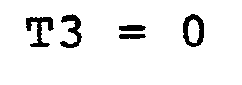
- Si au bout de 15s T2 n'a pas reçu d'impulsion sur son entrée venant de D2, celui-ci passe à l'état zéro et le respirateur se met en fonctionnement; dès l'instant où celui-ci se met en marche , T3 reçoit une impulsion et temporise pour un temps réglé par exemple à 5 mn.
- Si au bout de 5 mn celui-ci n'a plus reçu d'impulsion venant de D3 ou d'un second ordre éventuel de mise en marche du respirateur, la sortie de T3 passe alors à zéro et on a arrêt du respirateur.
- La détection maxi s'opère comme suit. Au moment où FCO2max est dépassé, D1 prend l'état zéro, T1 passe à un pour 15s et B1 est mise à zéro par la ligne 44. A la fin de l'expiration commence la période d'inspiration suivante avec FCO2= 0 donc les trois détecteurs prennent l'état un. L'état un de D2 est appliqué par les lignes 41 et 42 sur les entrées C de B1 et B2. Cela n'a aucun effet sur B1 qui n'est sensible qu'à un état zéro, mais B2 est sensible à l'état un. Comme la sortie S de B1 est à l'état zéro, qui est appliqué à l'entrée D de B2, cet état est transmis à la sortie S de B2 par le passage à l'état un de D2. A la remontée due à l'expiration suivante, D2 reprend l'état zéro ce qui fait prendre à la sortie S de B1 l'état de Tl, c'est-à-dire un.
- Deux cas peuvent se présenter :
- 1) on refranchit le seuil Dl : B1 est remis à zéro, puis on repasse sous le seuil D2, la sortie S de B2 prend l'état de Bl, c'est-à-dire zéro, qu'elle avait déjà. Cet état zéro est appliqué à l'entrée D de B3 mais n'est pas transmis à la sortie qui reste à l'état un. Donc chaque fois que FC02 franchit seuil maxi, seuil mini, seuil maxi ... etc l'opération se répète pendant tout le temps de la temporisation de T1. T2 est à l'état un, la commande manuelle aussi en l'absence d'actionnement, les trois entrées 31, 32, 33 de la bascule 37 étant à l'état un, celle-ci ne déclenche pas la mise en marche 35 du respirateur. Au moment où Tl revient à zéro, il envoie une impulsion sur la commande C de B3, ce qui fait passer la sertie S de B3 à l'état de D, c'est-à-dire l'état S de B2 qui reste à zéro. Le passage de la sortie S de B3 à l'état zéro commande la mise en marche du respirateur.
- 2) on ne refranchit pas le seuil Dl au cours de la temporisation de Tl mais on franchit le seuil D2. Bl n'est pas remise à zéro ; B2 prend alors l'état un quand D2 prend l'état un ce qui, par la ligne 47, met la sortie de B3 à l'état un et remet à zéro Tl. Rien ne se passe et le respirateur reste à l'arrêt.
- En résumé, si D1 est franchi entre un franchissement vers le haut et un franchissement vers le bas de D2, B2 reste à l'état zéro et le respirateur se met en marche au bout du temps T1. Mais si D2 est franchi vers le haut, puis vers le bas, sans que Dl ait été dépassé, B2 se met à l'état un lors du passage de D2 vers le bas. Si B2 est à l'état un à la fin de Tl, il n'y a pas mise en route du respirateur.
- En cas de coupure secteur ou de mise en stand by par la commande 56, l'état du respirateur est mis en mémoire en 49 et est restitué lorsque le secteur revient ou lorsque l'on relâche le bouton stand by.
- La figure 4 représente un exemple de montage pratique avec les signes conventionnels et les valeurs des composants. L'homme de l'art peut ainsi réaliser complètement le dispositif de l'invention. Il est évident que des variantes ou des équivalents sont possibles, tant dans le détail du montage que du choix des composants ou de leurs valeurs.
- La figure 5 représente l'évolution de la teneur en CO2 du gaz expiré au cours d'une journée. VC signifie ventilation contrôlée et VS ventilation spontanée. On voit que l'appareil a l'avantage de maintenir une PaCO2 constante au cours de la journée.
- La figure 2 représente une séquence de ventilation spontanée, jusqu'à la fin F1 de Tl, ventilation contrôlée jusqu'à la fin F2 de T2, puis ventilation spontanée à nouveau.
- L'utilisation d'un microprocesseur permettra une détection plus précoce de la valeur de FC02ET et un moyennage sur trois cycles, de fixer plus précisément les valeurs des différents seuils, de fixer des durées variables suivant les malades pour T1 et T2, et surtout d'envisager entre le mode de ventilation contrôlée et le mode spontané, un passage en ventilation intermittente à la demande (IMV) progressivement dégradé.
- Le passage ventilation spontanée → ventilation contrôlée s'effectuera donc comme précédemment, mais le passage ventilation contrôlée → ventilation spontanée s'effectuera plus progressivement permettant une meilleure adaptation du malade à la ventilation spontanée.
- La figure 6 représente une période de sevrage progressif avec passage en mode IMV : ventilation forcée intermittente. On a une ventilation spontanée jusqu'à la fin Fl de Tl, une ventilation contrôlée jusqu'à la fin F2 de T2 puis une ventilation IMV jusqu'à F3 et ensuite une ventilation spontanée.
- Tout dépassement en mode IMV pendant une durée supérieure à Tl de FC02max enclenche le mode contrôlé et la procédure recommence.
- Le temps T3 = durée de chacun des types IMV (2/1, 3/1, 4/1, etc) peut être fixe, de l'ordre de 3 mn, ou variable, réglable par le médecin pour chaque malade.
- L'utilisation d'un mircoprocesseur pourra également permettre de tenir compte de la fréquence ventilatoire dans le mode spontané ; le dépassement d'un seuil maxima et minima entraînant la mise en marche du respirateur dans le mode contrôlé. Cette prise en compte de la fréquence ventilatoire est une amélioration possible du système.
Claims (7)
1. Procédé de commande de la respiration artificielle d'un patient placé sous l'assistance d'un respirateur artificiel caractérisé en ce que la mise en marche et l'arrêt du respirateur sont commandés en fonction de la teneur en C02 en fin d'expiration FCO2ET du gaz expiré par le patient.
2. Procédé selon la revendication 1, caractérisé en ce que l'on détermine un seuil maximum FC02max et un seuil minimum FC02min de la teneur en C02 du gaz expiré par le patient et que tant que le patient présente une ventilation spontanée avec FC02min <FCO2ET <FCO2max il reste en ventilation spontanée, et dès qu'il dépasse les seuils, de façon constante pendant une durée supérieure à une durée choisie arbitrairement, on met le patient en ventilation contrôlée.
3. Procédé selon la revendication 2, caractérisé en ce que l'on détermine un troisième seuil FC02int intermédiaire entre les deux premiers et que l'on arrête la ventilation contrôlée si l'on a 
pendant une période choisie de l'ordre de 5 mn.
4. Dispositif pour la mise en oeuvre du procédé selon une des revendications 1 à 3, caractérisé en ce qu'il comprend un respirateur artificiel (1) avec une conduite (3) d'inspiration et une conduite (4) d'expiration connectées toutes deux à une sonde d'intubation, de trachéotomie, ou à un masque (2), une cellule (6) d'analyse de la teneur en CO2 du gaz qui la traverse placée sur une conduite commune à l'aspiration et à l'expiration, un capnigraphe (8) connecté à la cellule et transformant les signaux reçus de celle-ci pour délivrer des signaux transformés à un module de commande, et un module (11) de commande recevant les signaux du capnigraphe pour commander la mise en marche ou la mise à l'arrêt du respirateur, le module étant organisé pour commander la mise en marche ou la mise à l'arrêt du respirateur en fonction de la teneur en CO2 en fin d'expiration du gaz expiré.
5. Dispositif selon la revendication 4, caractérisé en ce que le capnigraphe (8) délivre au module une tension électrique proportionnelle à chaque instant à la teneur en C02 du gaz aspiré ou expiré, que le module (11) comporte trois détecteurs Dl, D2, D3 disposés en parallèles et auxquels est appliquée la sortie du capnigraphe, les détecteurs étant réglables en tension de façon à prendre un état ou un autre selon que la tension appliquée est supérieure ou inférieure à la tension de réglage, et un circuit logique tel que, si l'on désigne par FCO2ET la tension maxima délivrée par le capnigraphe à chaque expiration , pour 
le circuit logique ne commande pas la mise en marche du ventilateur mais la commande, si FCO2ET sort des limites D2, D1 de façon constante pendant une durée choisie de l'ordre de 15s, et commande la mise à l'arrêt du ventilateur si la condition D2 <FCO2ET <D3 est satisfaite pendant une période de temps choisie, de l'ordre de quelques minutes : 3 à 5.
6. Dispositif selon la revendication 5, caractérisé en ce que la mise en marche ou à l'arrêt du ventilateur est commandée par une bascule (35,36) sensible à un état zéro sur une de ses entrées, que les détecteurs Dl, D2, D3 sont des bistables prenant l'état zéro quand la tension appliquée est supérieure à la tension de réglage, et un état un (haut) quand la tension appliquée est inférieure à la tension de réglage, chaque détecteur Dl, D2, D3 étant connecté directement à une temporisation associée respectivement T1, T2, T3.
7. Dispositif selon la revendication 6, caractérisé en ce que la temporisation T1 est branchée sur la commande (35, 36) du respirateur à travers une bascule B3 dont le niveau est commandé par deux bascules B1, B2 en série, le niveau de B1 étant commandé par Dl et D2 et le niveau de B2 étant commandé par B1 et D2.
Applications Claiming Priority (2)
| Application Number | Priority Date | Filing Date | Title |
|---|---|---|---|
| FR8123193 | 1981-12-11 | ||
| FR8123193A FR2517961A1 (fr) | 1981-12-11 | 1981-12-11 | Procede et dispositif pour commander la respiration artificielle |
Publications (1)
| Publication Number | Publication Date |
|---|---|
| EP0082041A1 true EP0082041A1 (fr) | 1983-06-22 |
Family
ID=9264922
Family Applications (1)
| Application Number | Title | Priority Date | Filing Date |
|---|---|---|---|
| EP82402173A Withdrawn EP0082041A1 (fr) | 1981-12-11 | 1982-11-29 | Procédé et dispositif pour commander la respiration artificielle |
Country Status (9)
| Country | Link |
|---|---|
| US (1) | US4537190A (fr) |
| EP (1) | EP0082041A1 (fr) |
| JP (1) | JPS58105762A (fr) |
| AR (1) | AR229775A1 (fr) |
| BR (1) | BR8207176A (fr) |
| ES (1) | ES8308209A1 (fr) |
| FR (1) | FR2517961A1 (fr) |
| IL (1) | IL67428A0 (fr) |
| MX (1) | MX152294A (fr) |
Cited By (5)
| Publication number | Priority date | Publication date | Assignee | Title |
|---|---|---|---|---|
| WO1990014852A1 (fr) * | 1989-06-07 | 1990-12-13 | Caduceus Limited | Ameliorations apportees aux ventilateurs medicaux |
| US5271388A (en) * | 1989-06-07 | 1993-12-21 | Caduceus Limited | Medical ventilator |
| EP0569241A3 (en) * | 1992-05-07 | 1994-05-18 | Cook William A Australia | An improved apparatus and method for insufflation with gas |
| EP1060755A1 (fr) * | 1995-07-10 | 2000-12-20 | Burkhard Prof. Dr. Lachmann | Dispositif de respiration artificielle |
| WO2001000265A1 (fr) * | 1999-06-30 | 2001-01-04 | University Of Florida | Ventilateur medical et procede pour le commander |
Families Citing this family (50)
| Publication number | Priority date | Publication date | Assignee | Title |
|---|---|---|---|---|
| US4648396A (en) * | 1985-05-03 | 1987-03-10 | Brigham And Women's Hospital | Respiration detector |
| US5522382A (en) * | 1987-06-26 | 1996-06-04 | Rescare Limited | Device and method for treating obstructed breathing having a delay/ramp feature |
| US5199424A (en) * | 1987-06-26 | 1993-04-06 | Sullivan Colin E | Device for monitoring breathing during sleep and control of CPAP treatment that is patient controlled |
| US4986268A (en) * | 1988-04-06 | 1991-01-22 | Tehrani Fleur T | Method and apparatus for controlling an artificial respirator |
| US5165397A (en) * | 1988-12-15 | 1992-11-24 | Arp Leon J | Method and apparatus for demand oxygen system monitoring and control |
| AU651627B2 (en) * | 1990-09-19 | 1994-07-28 | University Of Melbourne, The | Arterial CO2 monitor and closed loop controller |
| US5402796A (en) * | 1990-09-19 | 1995-04-04 | University Of Melbourne | Arterial CO2 Monitor and closed loop controller |
| US5320093A (en) * | 1990-12-21 | 1994-06-14 | Brigham And Women's Hospital | Rapid anesthesia emergence system using closed-loop PCO2 control |
| US5193544A (en) * | 1991-01-31 | 1993-03-16 | Board Of Trustees Of The Leland Stanford Junior University | System for conveying gases from and to a subject's trachea and for measuring physiological parameters in vivo |
| FI921924A7 (fi) * | 1991-05-08 | 1992-11-09 | Nellcor Inc | Portabel koldioxidmonitor |
| US5203343A (en) * | 1991-06-14 | 1993-04-20 | Board Of Regents, The University Of Texas System | Method and apparatus for controlling sleep disorder breathing |
| US5095896A (en) * | 1991-07-10 | 1992-03-17 | Sota Omoigui | Audio-capnometry apparatus |
| US5645054A (en) * | 1992-06-01 | 1997-07-08 | Sleepnet Corp. | Device and method for the treatment of sleep apnea syndrome |
| EP0645119A3 (fr) * | 1993-09-27 | 1998-04-15 | Ohmeda Inc. | Logiciel d'invalidation d'un dispositif de surveillance volumétrique d'apnée |
| DE69422900T2 (de) | 1993-12-01 | 2000-06-08 | Resmed Ltd., North Ryde | Vorrichtung zur Erzeugung eines kontinuierlichen positiven Atemwegdruckes (CPAP) |
| AUPM279393A0 (en) * | 1993-12-03 | 1994-01-06 | Rescare Limited | Estimation of flow and detection of breathing in cpap treatment |
| US5622182A (en) * | 1994-06-27 | 1997-04-22 | Jaffe; Richard A. | System for measuring core body temperature in vivo |
| US5720277A (en) * | 1995-02-27 | 1998-02-24 | Siemens Elema Ab | Ventilator/Anaesthetic system with juxtaposed CO2 meter and expired gas flow meter |
| US5598838A (en) * | 1995-04-07 | 1997-02-04 | Healthdyne Technologies, Inc. | Pressure support ventilatory assist system |
| US6135107A (en) * | 1996-03-11 | 2000-10-24 | Mault; James R. | Metabolic gas exchange and noninvasive cardiac output monitor |
| AUPN973596A0 (en) | 1996-05-08 | 1996-05-30 | Resmed Limited | Control of delivery pressure in cpap treatment or assisted respiration |
| AUPO247496A0 (en) | 1996-09-23 | 1996-10-17 | Resmed Limited | Assisted ventilation to match patient respiratory need |
| US5778874A (en) * | 1996-10-02 | 1998-07-14 | Thomas Jefferson University | Anesthesia machine output monitor |
| AUPO511397A0 (en) * | 1997-02-14 | 1997-04-11 | Resmed Limited | An apparatus for varying the flow area of a conduit |
| US5915380A (en) | 1997-03-14 | 1999-06-29 | Nellcor Puritan Bennett Incorporated | System and method for controlling the start up of a patient ventilator |
| JPH11206884A (ja) * | 1998-01-21 | 1999-08-03 | Tadashi Nemoto | ファジー理論制御を用いた人工呼吸器の自動ウィニングシステムおよび自動ウィニングプログラムを記録した記録媒体 |
| EP1115448A4 (fr) * | 1998-09-23 | 2002-05-08 | Univ Johns Hopkins | Materiel de survie |
| US20070000494A1 (en) * | 1999-06-30 | 2007-01-04 | Banner Michael J | Ventilator monitor system and method of using same |
| US6951216B2 (en) * | 2002-12-19 | 2005-10-04 | Instrumentarium Corp. | Apparatus and method for use in non-invasively determining conditions in the circulatory system of a subject |
| US8336549B2 (en) * | 2003-12-29 | 2012-12-25 | Ramses Nashed | Disposable anesthesia face mask |
| DE102006012727B4 (de) | 2005-07-19 | 2025-06-18 | Löwenstein Medical Technology S.A. | Beatmungsgerät mit Betriebsdatenspeicher |
| US8021310B2 (en) | 2006-04-21 | 2011-09-20 | Nellcor Puritan Bennett Llc | Work of breathing display for a ventilation system |
| US7784461B2 (en) | 2006-09-26 | 2010-08-31 | Nellcor Puritan Bennett Llc | Three-dimensional waveform display for a breathing assistance system |
| US20080230062A1 (en) * | 2007-03-23 | 2008-09-25 | General Electric Company | Setting expiratory time in mandatory mechanical ventilation based on a deviation from a stable condition of exhaled gas volumes |
| EP2303376B1 (fr) | 2008-05-28 | 2016-03-30 | Oridion Medical 1987 Ltd. | Sonde d'intubation endotrachéale de suivi du co2 |
| US20100218766A1 (en) * | 2009-02-27 | 2010-09-02 | Nellcor Puritan Bennett Llc | Customizable mandatory/spontaneous closed loop mode selection |
| US8924878B2 (en) | 2009-12-04 | 2014-12-30 | Covidien Lp | Display and access to settings on a ventilator graphical user interface |
| US9119925B2 (en) | 2009-12-04 | 2015-09-01 | Covidien Lp | Quick initiation of respiratory support via a ventilator user interface |
| US8335992B2 (en) | 2009-12-04 | 2012-12-18 | Nellcor Puritan Bennett Llc | Visual indication of settings changes on a ventilator graphical user interface |
| US9262588B2 (en) | 2009-12-18 | 2016-02-16 | Covidien Lp | Display of respiratory data graphs on a ventilator graphical user interface |
| US8499252B2 (en) | 2009-12-18 | 2013-07-30 | Covidien Lp | Display of respiratory data graphs on a ventilator graphical user interface |
| US9126000B2 (en) * | 2010-02-26 | 2015-09-08 | Nihon Kohden Corporation | Artificial ventilation apparatus |
| JP5570853B2 (ja) * | 2010-02-26 | 2014-08-13 | 日本光電工業株式会社 | 人工呼吸装置 |
| US9901695B2 (en) | 2010-06-22 | 2018-02-27 | Koninklijke Philips N.V. | Respiratory interface apparatus |
| US20130053717A1 (en) * | 2011-08-30 | 2013-02-28 | Nellcor Puritan Bennett Llc | Automatic ventilator challenge to induce spontaneous breathing efforts |
| US10362967B2 (en) | 2012-07-09 | 2019-07-30 | Covidien Lp | Systems and methods for missed breath detection and indication |
| US9950129B2 (en) | 2014-10-27 | 2018-04-24 | Covidien Lp | Ventilation triggering using change-point detection |
| EP3334341B1 (fr) * | 2015-08-11 | 2019-12-25 | Koninklijke Philips N.V. | Système d'accessoire d'échantillonnage automatique |
| EP3383463B1 (fr) * | 2015-12-01 | 2022-09-07 | Koninklijke Philips N.V. | Dispositif pour le traitement de la respiration ataxique |
| US11672934B2 (en) | 2020-05-12 | 2023-06-13 | Covidien Lp | Remote ventilator adjustment |
Citations (4)
| Publication number | Priority date | Publication date | Assignee | Title |
|---|---|---|---|---|
| GB798561A (en) * | 1955-01-27 | 1958-07-23 | Arnold St Jacques Lee | Improvements in or relating to apparatus for the administration of substances to living subjects |
| DE2424025B1 (de) * | 1974-05-17 | 1975-11-20 | Original Hanau Quarzlampen Gmbh, 6450 Hanau | Beatmungsgerät |
| EP0022144A1 (fr) * | 1979-07-03 | 1981-01-14 | Drägerwerk Aktiengesellschaft | Respirateur artificiel commandé par des valeurs mesurées sur le patient |
| GB2079984A (en) * | 1980-06-18 | 1982-01-27 | Engstrom Medical Ab | Improvements in or relating to a method and apparatus for controlling lung ventilators |
Family Cites Families (6)
| Publication number | Priority date | Publication date | Assignee | Title |
|---|---|---|---|---|
| US3693653A (en) * | 1971-01-29 | 1972-09-26 | Robert L Cramer | Fluid mixing regulator |
| SU459242A1 (ru) * | 1973-02-20 | 1975-02-05 | Всесоюзный научно-исследовательский институт горноспасательного дела | Стенд-имитатор внешнего дыхани человека |
| US3951137A (en) * | 1974-11-20 | 1976-04-20 | The United States Of America As Represented By The Secretary Of The Air Force | Rebreathing system |
| DE2507981B2 (de) * | 1975-02-25 | 1977-03-31 | Drägerwerk AG, 2400 Lübeck | Vorrichtung zur steuerung der atmung in beatmungsgeraeten |
| US4121578A (en) * | 1976-10-04 | 1978-10-24 | The Bendix Corporation | Physiological responsive control for an oxygen regulator |
| US4188946A (en) * | 1977-10-07 | 1980-02-19 | Rayburn Robert L | Controllable partial rebreathing anesthesia circuit and respiratory assist device |
-
1981
- 1981-12-11 FR FR8123193A patent/FR2517961A1/fr active Granted
-
1982
- 1982-11-29 EP EP82402173A patent/EP0082041A1/fr not_active Withdrawn
- 1982-12-07 US US06/447,584 patent/US4537190A/en not_active Expired - Fee Related
- 1982-12-07 IL IL67428A patent/IL67428A0/xx unknown
- 1982-12-08 MX MX195496A patent/MX152294A/es unknown
- 1982-12-09 AR AR291535A patent/AR229775A1/es active
- 1982-12-10 JP JP57217657A patent/JPS58105762A/ja active Pending
- 1982-12-10 BR BR8207176A patent/BR8207176A/pt unknown
- 1982-12-10 ES ES518088A patent/ES8308209A1/es not_active Expired
Patent Citations (4)
| Publication number | Priority date | Publication date | Assignee | Title |
|---|---|---|---|---|
| GB798561A (en) * | 1955-01-27 | 1958-07-23 | Arnold St Jacques Lee | Improvements in or relating to apparatus for the administration of substances to living subjects |
| DE2424025B1 (de) * | 1974-05-17 | 1975-11-20 | Original Hanau Quarzlampen Gmbh, 6450 Hanau | Beatmungsgerät |
| EP0022144A1 (fr) * | 1979-07-03 | 1981-01-14 | Drägerwerk Aktiengesellschaft | Respirateur artificiel commandé par des valeurs mesurées sur le patient |
| GB2079984A (en) * | 1980-06-18 | 1982-01-27 | Engstrom Medical Ab | Improvements in or relating to a method and apparatus for controlling lung ventilators |
Non-Patent Citations (1)
| Title |
|---|
| MEDICAL & BIOLOGICAL ENGINEERING, vol. 13, no. 6, novembre 1975, pages 846-854, Stevenage, Herts (GB); * |
Cited By (10)
| Publication number | Priority date | Publication date | Assignee | Title |
|---|---|---|---|---|
| WO1990014852A1 (fr) * | 1989-06-07 | 1990-12-13 | Caduceus Limited | Ameliorations apportees aux ventilateurs medicaux |
| US5271388A (en) * | 1989-06-07 | 1993-12-21 | Caduceus Limited | Medical ventilator |
| US5307795A (en) * | 1989-06-07 | 1994-05-03 | Caduceus Limited | Medical ventilators |
| EP0569241A3 (en) * | 1992-05-07 | 1994-05-18 | Cook William A Australia | An improved apparatus and method for insufflation with gas |
| EP1060755A1 (fr) * | 1995-07-10 | 2000-12-20 | Burkhard Prof. Dr. Lachmann | Dispositif de respiration artificielle |
| WO2001000265A1 (fr) * | 1999-06-30 | 2001-01-04 | University Of Florida | Ventilateur medical et procede pour le commander |
| US6796305B1 (en) | 1999-06-30 | 2004-09-28 | University Of Florida Research Foundation, Inc. | Ventilator monitor system and method of using same |
| US7066173B2 (en) | 1999-06-30 | 2006-06-27 | University Of Florida Research Foundation, Inc. | Medical ventilator and method of controlling same |
| US7210478B2 (en) | 1999-06-30 | 2007-05-01 | University Of Florida Research Foundation, Inc. | Ventilator monitor system and method of using same |
| US8122883B2 (en) | 1999-06-30 | 2012-02-28 | University Of Florida Research Foundation, Inc. | Medical ventilator and method of controlling same |
Also Published As
| Publication number | Publication date |
|---|---|
| FR2517961A1 (fr) | 1983-06-17 |
| FR2517961B1 (fr) | 1984-03-16 |
| IL67428A0 (en) | 1983-05-15 |
| AR229775A1 (es) | 1983-11-30 |
| US4537190A (en) | 1985-08-27 |
| BR8207176A (pt) | 1983-10-11 |
| ES518088A0 (es) | 1983-09-01 |
| JPS58105762A (ja) | 1983-06-23 |
| MX152294A (es) | 1985-06-21 |
| ES8308209A1 (es) | 1983-09-01 |
Similar Documents
| Publication | Publication Date | Title |
|---|---|---|
| EP0082041A1 (fr) | Procédé et dispositif pour commander la respiration artificielle | |
| EP3821929B1 (fr) | Dispositif de fourniture de gaz thérapeutique, en particulier de no ou de n2o, à un patient | |
| EP0344280A1 (fr) | Procédé de fonctionnement d'un dispositif de ventilation artificielle et un tel dispositif. | |
| CA2275209A1 (fr) | Dispositif de determination de phases respiratoires du sommeil d'un utilisateur | |
| EP3320463A1 (fr) | Interface utilisateur tactile destinée à un dispositif de stimulation de l'air trachéo-bronchique | |
| EP0182722A1 (fr) | Appareil de ventilation artificielle pourvu d'un dispositif d'assistance inspiratoire volumétrique | |
| FR2811577A1 (fr) | Installation de ventilation en gaz d'un patient | |
| EP3323457B1 (fr) | Appareil de ventilation artificielle avec modes ventilatoires adaptés au massage cardiaque | |
| EP3510924B1 (fr) | Appareil de ventilation pour réanimation cardio-pulmonaire avec affichage de la tendance en co2 | |
| US11246506B2 (en) | Automatic sampling accessory system and method of detection | |
| CA3023591A1 (fr) | Appareil de ventilation pour reanimation cardio-pulmonaire avec monitorage et affichage de la valeur maximale de co2 mesuree | |
| FR2767466A1 (fr) | Procede pour determiner l'image du flux respiratoire nasal et/ou buccal d'un utilisateur | |
| EP4406575B1 (fr) | Ventilateur médical avec affichage d'une indication de la recrutabilité des poumons d'un patient | |
| FR2596279A1 (fr) | Appareil de ventilation artificielle pour l'assistance inspiratoire volumetrique d'un patient | |
| EP4180074B1 (fr) | Détection du débranchement du circuit patient d'un ventilateur médical à partir de la compliance | |
| EP4180076B1 (fr) | Détection du débranchement du circuit patient d'un ventilateur médical à partir de la résistance | |
| EP4417235B1 (fr) | Appareil de fourniture de gaz, tel du no, à un patient avec comptage du temps total de traitement effectif | |
| FR3118694A1 (fr) | Boitier autonome de monitorage d’une ventilation délivrée pendant une réanimation cardio-pulmonaire | |
| FR3161569A3 (fr) | Détection du débranchement du circuit patient d’un ventilateur médical | |
| EP4616892A1 (fr) | Ventilateur médical affichant la pression d'ouverture des voies aériennes du patient | |
| Smye et al. | A temperature-sensitive respiratory alarm | |
| FR2766718A1 (fr) | Appareil de diagnostic ou de traitement de troubles respiratoires du sommeil | |
| WO1992003091A1 (fr) | Procede de mesure du niveau d'hyperinsufflation d'un patient sous assistance ventilatoire |
Legal Events
| Date | Code | Title | Description |
|---|---|---|---|
| PUAI | Public reference made under article 153(3) epc to a published international application that has entered the european phase |
Free format text: ORIGINAL CODE: 0009012 |
|
| AK | Designated contracting states |
Designated state(s): AT BE CH DE FR GB IT LI LU NL SE |
|
| 17P | Request for examination filed |
Effective date: 19831214 |
|
| STAA | Information on the status of an ep patent application or granted ep patent |
Free format text: STATUS: THE APPLICATION IS DEEMED TO BE WITHDRAWN |
|
| 18D | Application deemed to be withdrawn |
Effective date: 19850917 |
|
| RIN1 | Information on inventor provided before grant (corrected) |
Inventor name: CHOPIN, CLAUDE Inventor name: CAILLOT, LUC |