EP0082254A2 - Appareil pour la formation d'une image - Google Patents
Appareil pour la formation d'une image Download PDFInfo
- Publication number
- EP0082254A2 EP0082254A2 EP82108933A EP82108933A EP0082254A2 EP 0082254 A2 EP0082254 A2 EP 0082254A2 EP 82108933 A EP82108933 A EP 82108933A EP 82108933 A EP82108933 A EP 82108933A EP 0082254 A2 EP0082254 A2 EP 0082254A2
- Authority
- EP
- European Patent Office
- Prior art keywords
- image forming
- forming apparatus
- unit
- photosensitive body
- corona
- Prior art date
- Legal status (The legal status is an assumption and is not a legal conclusion. Google has not performed a legal analysis and makes no representation as to the accuracy of the status listed.)
- Granted
Links
Images




Classifications
-
- G—PHYSICS
- G03—PHOTOGRAPHY; CINEMATOGRAPHY; ANALOGOUS TECHNIQUES USING WAVES OTHER THAN OPTICAL WAVES; ELECTROGRAPHY; HOLOGRAPHY
- G03G—ELECTROGRAPHY; ELECTROPHOTOGRAPHY; MAGNETOGRAPHY
- G03G15/00—Apparatus for electrographic processes using a charge pattern
- G03G15/02—Apparatus for electrographic processes using a charge pattern for laying down a uniform charge, e.g. for sensitising; Corona discharge devices
- G03G15/0291—Apparatus for electrographic processes using a charge pattern for laying down a uniform charge, e.g. for sensitising; Corona discharge devices corona discharge devices, e.g. wires, pointed electrodes, means for cleaning the corona discharge device
Definitions
- the present invention relates to an image forming apparatus comprising a corona discharging device provided at a predetermined interval from the surface of a photosensitive body and, more particularly, to an image forming apparatus such as an electrostatic copying apparatus or an electronic printer in which a corona discharging device is used for a charger, a transfer unit and a peeling unit.
- corona discharging devices are normally disposed as a charger, a transfer unit, a sheet peeling unit and a static eliminator at positions in the vicinity of the periphery of the photosensitive body.
- the relative position between the photosensitive body and the corona discharging device has heretofore been defined by the contact between frames of the upper and lower units to each other. Accordingly, the relative position between the photosensitive body and the corona discharging device might not have been constantly defined due to irregularities in the dimensional and assembling accuracy at the time of manufacture. Further, when the upper unit has been repeatedly opened and closed, the pivotal position tended to shift slightly, with the result that the relative position between the photosensitive body and the corona discharging device might have varied. Thus, the conventional corona dischargers could not have stably performed corona discharge, causing improper transfer of an image or improper peeling of a sheet as its drawbacks.
- an image forming apparatus which comprises: a housing including a lower unit and an upper unit swingably supported to the lower unit; a photosensitive body housed in the housing and rotatably supported by the upper unit; a fixed member attached to the upper unit and having a fixed position relative to the photosensitive body; and a corona discharging device provided in the lower unit and including a corona charger provided with a base member fixed to the lower unit and facing the photosensitive body, a case attached to the base member being movable between the photosensitive body and the base member and opening to the photosensitive body and a charging wire housed in the case, the charging wire and photosensitive body being adapted to be connected to a power supply; urging means for moving the case in one direction toward the photosensitive body, and a positioning member fixed to the corona charger and being in contact with the fixed member to move the corona charger in a direction opposite to the one direction against the urging means when the upper unit is swung to close the housing,
- the corona charger is swingably supported to the lower unit in a direction contacting with or separating from the photosensitive body provided in the upper unit and is always elastically urged toward the photosensitive body.
- the positioning member provided integrally with the corona charger is contacted with the photosensitive body or a member fixed to the photosensitive body, thereby accurately positioning the corona charger to the photosensitive body.
- Fig. 1 shows the structure of an electrostatic copying apparatus according to the present invention provided with a corona discharging device applied to a transfer unit as a peeling unit.
- reference number 1 designates a body of the electrostatic copying apparatus.
- an original platform 2 On the upper surface of the body 1 is placed an original platform 2, which can be reciprocatedly moved in the directions indicated by arrows X as required.
- an exhaust sheet tray At the left side of the body 1 is detachably provided an exhaust sheet tray, and at the right side of the body 1 are detachably provided a cassette 4 for containing copy sheets P and a manual guide 5.
- a photosensitive drum 6 rotatably driven in a clockwise direction.
- a charger 7 Around this photosensitive drum 6 are sequentially arranged in the rotating direction a charger 7, an exposure device 8, a developing device 9, a transfer unit 10, a peeling unit 11, a static eliminator 12, a cleaning device 13 and an after-image erasing device 14.
- the exposure device 8 includes an illumination system 8a which illuminates an original (not shown) placed on the original platform 2 and a light converging transmission device 8b which converges the reflected light from the original to the surface of the photosensitive drum 6.
- sheet feeding mechanisms 15 and 16 respectively feed copy sheets P in the cassette 4 and copy sheets manually inserted via the manual guide 5 into a sheet conveying passage 17.
- This sheet conveying passage 17 extends between the sheet feeding mechanisms 15 and 16 and the exhaust sheet tray 3 in the body 1, and is formed of a pair of conveying rollers 18, a conveying belt 19, a pair of exhaust sheet rollers 20 and guide plates 21 suitably disposed therebetween.
- the midpoint of the sheet conveying passage 17 passes through a transfer section defined by the photosensitive drum 6 and the transfer unit 10.
- a pair of fixing rollers 22 At the end side of the sheet conveying passage 17 are disposed a pair of fixing rollers 22.
- a motor 23 which is the prime driver of both the original platform 2 and the photosensitive drum 6, and a cooling device 24 for preventing the heater section in the body 1 from overheating.
- Reference numeral 25 designates an exhaust sheet detection switch provided in the vicinity of the exhaust sheet rollers 20 provided on the sheet conveying passage 17.
- the copy sheet P thus peeled is conveyed through the sheet conveying passage 17 to the exhaust sheet tray 3. Then, the developer image is fixed onto the copy sheet P by the pair of fixing rollers 22.
- the surface of the photosensitive drum 6 thus transferred with the developer image is cleaned by sequentially facing the static eliminator 12, cleaning device 13 and after-image erasing device 14, and is then once again faced to the charger 7.
- the body 1 of the copying apparatus thus constructed includes an upper unit 26 and a lower unit 28 formed by dividing the body 1 at the boundary of a line L substantially along the sheet conveying passage 17.
- the upper unit 26 is rotatably pivoted at one end to the lower unit 28 to rotatably displace upwards at an angle 6 as required to be raised from the lower unit 28, and the sheet conveying passage 17 is opened.
- most of the sheet conveying passage 17 can be opened by swinging the upper unit 26, and the clogged or jammed sheet P can be readily removed.
- the photosensitive drum 6 is provided at a pair of frames 27 of the upper unit 26 side and the transfer unit 10 and the peeling unit 11 are provided at a pair of frames 29 of the lower unit 28 side.
- the transfer unit 10 and the peeling unit 11 are respectively defined by the first and second corona discharging sections of a corona discharging device 30 as will be described later. Accordingly, in the state that the upper unit 26 is superposed with the lower unit 28, the intervals between the photosensitive drum 6 and both the transfer unit 10 and the peeling unit 11 are always maintained at the predetermined value.
- a corona discharger 34 is constructed which includes a first corona discharging section as the transfer unit 10 and a second corona discharging section as the peeling unit 11 disposed adjacent to each other.
- Supporting projections 35 extending downwardly are provided on the lower surfaces of both ends of the discharger body 31 of the corona discharger 34.
- the supporting projections 35 are engaged with recesses of supporting members 36 which are clamped by screws to the frames 29 of the lower unit 28.
- coil springs 37 are contained in the recesses as elastic supporting members.
- the discharger body 31 is thus elastically supported via the coil springs 37. In this manner, the corona discharger 34 is swingably provided in the contacting and separating direction relative to the photosensitive drum 6 and is always urged toward the photosensitive drum 6.
- the intervals between the surface of the photosensitive drum 6 and the discharging wires 33a and 33b of the first and second corona discharging sections as the transfer unit 10 and the peeling unit 11 can always be maintained constant with exremely stable corona discharging performance.
- a paper guide member 32c is attached to the top of the discharger body 31. The interval between the surfaces of the photosensitive drum 6 and the paper guide member 32c can always he maintained constant so that the feeding path for the copying paper P is defined reliably with extremely stable corona discharging performance.
- the guide rollers 39 are rotatably driven by the rotation of the photosensitive drum 6, and a high voltage is suitably applied through a flexible power supply wire 49a from a high voltage power supply 49 to the discharging wires 33a and 33b.
- a micrometer mechanism 40 may be associated as a control mechanism in each supporting arm 38 mounted with the guide roller 39.
- the micrometer mechanism 40 When the micrometer mechanism 40 is thus associated, the interval between the discharging wire 33b and the photosensitive drum 6 can be arbitrarily controlled. Therefore, it can facilitate the control of the corona discharging amount.
- the control mechanism may not always employ the micrometer mechanism 40, but may employ more simple screw mechanism so as to achieve the same object.
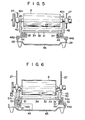
- the corona discharger 34 may not always be positioned directly by the surface of the photosensitive drum 6 but also by a supporting shaft 41 for rotatably supporting the photosensitive drum 6.
- the guide rollers 39 may be eliminated so as to obviate the scratches on the surface of the photosensitive drum 6.
- Shaft contacting parts 42a of supporting pieces 42 as positioning members which are contacted with the supporting shaft 41 may be preferably formed of self-lubricating resin.
- Oblique portions 43 may be formed along the shaft inserting direction at the shaft contacting parts 42a so that the shaft 41 may be smoothly inserted when the shaft 41 is slidably inserted into the photosensitive drum 6.
- the supporting members 44 of the floating corona discharger 34 may be mounted on the frames 29 provided integrally with the lower surface base 45 of the body 1 by engaging hooks 44a with the frames 29.
- a pair of supporting pieces 46 may be positioned as positioning members in contact with the pair of frames 27 of the upper unit 26 on which the photosensitive drum 6 is mounted.
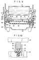
- One of the pair of coil springs 37 may be formed as elastic supporting members of a conductive material.
- the discharging wire 33 is stretched via terminals 47 and 48.
- the one end of the one coil spring 37 is connected to the one terminal 48 for applying a voltage to the discharging wire 33, and the other end of the coil spring 37 is contacted under pressure with the power supply portion 49b of the high voltage power supply 49.
- a voltage may be applied to the discharging wire 33 with this structure.
- a pair of engaging recesses 50 may be formed on both side faces of the discharger body 31 of the corona discharger 34 urged by the coil spring 37 as an elastic supporting member always toward the photosensitive drum 6.
- engaging pawls 51a are respectively formed at the ends of the engaging arms 51 extending from the power supply 49 and the supporting members 44 to be capable of being engaged with the engaging recesses 50.
- the engaging arms 51 may be formed of elastic synthetic resin.
- the corona discharging device 30 may be readily assembled merely by inserting the corona discharger 34 by elastically opening the engaging arms 51. Moreover, it not only restricts the elevational movements of the corona discharger 34 but can also simultaneously control the lateral movements of the corona discharger 34.
- the power supply 49 produces a necessary high voltage from a DC power source by the known method.
- the elastic supporting members operating also as a power supply member are formed of conductive coil springs.
- the elastic supporting members are not limited only to this particular structure.
- the power supply member may have a power supply side feeder 52 and a charger side power receiver 53 both formed of a conductive leaf spring. Both the feeder 52 and the receiver 53 become capable of being energized under pressure contact with each other at the respective contacts 52a and 53a when the upper unit 26 is superposed on the lower unit 28.
- the contacts 52a and 53a may be formed in an oblique state relative to the power supply side feeder 52 and the charger side power receiver 53. Accordingly, both the feeder 52 and the receiver 53 are slidably pressed against each other at the contacting time so that both the contacts 52a and 53a are cleaned by each other at every frictional contact, thereby preventing improper contact.
- the corona discharger 34 may be supported by the supporting members 54.
- the supporting members 54 contain the power supply 49 therein.
- the voltage produced from the power supply 49 is applied to the power supply side feeder 52.
- the supporting members 54 may be formed of elastic synthetic resin, and upper and lower engaging arms 55 and 56 may be respectively formed at both ends.
- the engaging pawls 55a of the lower engaging arms 55 are engaged with the engaging holes 57 formed at the frames 29 formed integrally with the lower base 45 of the lower unit 28.
- the supporting members 54 are fixed to the frames 47 by this engagement.
- the corona discharger 34 is provided between the both upper engaging arms 56, and the engaging pawls 56a are engaged with the engaging recesses 50 formed of the outside surfaces of the supporting pieces 46.
- the elevational and lateral movements of the corona discharger 34 may be restricted by this engagement.
- stopper members 58 are formed integrally at both ends of the supporting members 54. The lateral movements and the swingable rotation of the corona discharger 34 in Fig. 10 can be controlled.
- Oblique parts are formed similar to the oblique parts of the engaging pawls 56a of the engaging arms 56 at the portions corresponding to the engaging recesses 50 of both ends of the discharger body 31.
- the corona discharger 31 can be associated with the supporting members 54 by one- touch operation.
- the discharger body 31 is pushed upward by the repelling force between the power supply side feeder 52 and the charger side receiver 53 formed of a conductive leaf spring at the contacting time and also by the repelling force between the elastic pieces 60 formed on the lower surface of the discharge body 31 and the supporting members 54.
- the corona discharger 34 will not fall because of the engagement of the engaging pawls 56a of the engaging arms 56 with the engaging recesses 50.
- Both the elastic pieces 60 may be formed of resin integral with the discharger body 31, or may be formed of another member and may be mounted with the member, or may be mounted not at the discharger body 31 side but at the supporting members 54.
- the corona discharging device 30 thus constructed, when the upper unit 26 is integrally associated with the lower unit 28, the frames 27 are lowered and are contacted with the upper surfaces of the positioning members 46 of the discharger body 31, thereby pressing them down.
- the relative positional relationship between the corona discharger 34 and the frames 27 can be accurately determined by this depression.
- the interval between the frames 27 and the photosensitive drum 6 is predetermined, and the height of the discharging wires 33 provided between the terminals 48 and 47 may be controlled by a pair of height determining members (which includes eccentric screws (not shown) or other controlling mechanisms).
- the interval between the photosensitive drum 6 and the discharging wire 3 may be maintained constant.
- the discharger body 31 of the corona discharger 34 and the supporting members 54 may be formed integrally.
- Unit supporting members 63 having elasticity are formed at both ends of the discharging unit 62.
- the end parts of the unit supporting members 63 may be engaged with the engaging holes 64 formed at the frames 29.
- the discharging units 62 may be elastically supported by this engagement.
- the discharging units 62 may be formed integrally with the discharger body 31 and the supporting members 54, or may be formed of suitable material integrally.
- the same unit has the corona discharger 34, the power supply 49 and the unit supporting members 63 integrally, the adjustment of the unit can be readily performed, and the assembling and mounting of the discharging device can be simply performed, thereby largely reducing the number of steps of assembling and adjusting the copying apparatus. Also, contact points through which high voltage passes are omitted.
- this invention is applied to the copying apparatus.
- the present invention is not limited only to the particular embodiments, but may also be applied to any image forming apparatus in which a corona discharging device is disposed at the position at least adjacent to the surface of the photosensitive drum.
- the present invention comprises the corona discharger which is swingably and elastically supported in the direction contacting with or separating from the photosensitive drum always in the state urged toward the photosensitive drum side, and the positioning member which is provided integrally with the corona discharger and is contacted with the photosensitive drum or the member relatively fixedly disposed relative to the photosensitive drum, thereby positioning it relative to the photosensitive drum of the corona discharger. Therefore, the interval between the photosensitive drum and the corona discharger can always be maintained constant with a relatively simple structure, and can also perform always stable corona discharging operation.
Landscapes
- Physics & Mathematics (AREA)
- Engineering & Computer Science (AREA)
- Plasma & Fusion (AREA)
- General Physics & Mathematics (AREA)
- Electrostatic Charge, Transfer And Separation In Electrography (AREA)
Applications Claiming Priority (2)
| Application Number | Priority Date | Filing Date | Title |
|---|---|---|---|
| JP56208315A JPS58126544A (ja) | 1981-12-23 | 1981-12-23 | 画像形成装置におけるコロナ放電装置 |
| JP208315/81 | 1981-12-23 |
Publications (3)
| Publication Number | Publication Date |
|---|---|
| EP0082254A2 true EP0082254A2 (fr) | 1983-06-29 |
| EP0082254A3 EP0082254A3 (en) | 1984-03-07 |
| EP0082254B1 EP0082254B1 (fr) | 1986-03-12 |
Family
ID=16554217
Family Applications (1)
| Application Number | Title | Priority Date | Filing Date |
|---|---|---|---|
| EP82108933A Expired EP0082254B1 (fr) | 1981-12-23 | 1982-09-27 | Appareil pour la formation d'une image |
Country Status (4)
| Country | Link |
|---|---|
| US (1) | US4466729A (fr) |
| EP (1) | EP0082254B1 (fr) |
| JP (1) | JPS58126544A (fr) |
| DE (1) | DE3269848D1 (fr) |
Cited By (3)
| Publication number | Priority date | Publication date | Assignee | Title |
|---|---|---|---|---|
| EP0307942A3 (en) * | 1987-09-19 | 1990-03-14 | Fujitsu Limited | Mechanisms in image recording apparatus |
| EP0272094A3 (en) * | 1986-12-15 | 1990-04-18 | Xerox Corporation | Process unit for an imaging apparatus |
| US5317371A (en) * | 1990-04-13 | 1994-05-31 | Asahi Kogaku Kogyo Kabushiki Kaisha | Skew prevention structure for electrophotographic printer |
Families Citing this family (21)
| Publication number | Priority date | Publication date | Assignee | Title |
|---|---|---|---|---|
| US4575221A (en) * | 1982-05-20 | 1986-03-11 | Canon Kabushiki Kaisha | Process kit and an image forming apparatus using the same |
| JPS62115932A (ja) * | 1985-07-24 | 1987-05-27 | Toshiba Corp | 画像処理装置 |
| GB2198991B (en) * | 1986-12-15 | 1991-02-13 | Xerox Corp | Electrostatographic reproducing machine and process unit therefor |
| JPH07110546B2 (ja) * | 1988-05-25 | 1995-11-29 | インターナショナル ビジネス マシーンズ コーポレーション | 電子写真方式の印刷装置 |
| JPH087504B2 (ja) * | 1988-12-16 | 1996-01-29 | 長野日本無線株式会社 | プリンタの転写チャージャ装置 |
| JPH089727Y2 (ja) * | 1989-01-15 | 1996-03-21 | 三田工業株式会社 | 画像形成装置のチャージャ装置 |
| JP2749609B2 (ja) * | 1989-01-31 | 1998-05-13 | 株式会社リコー | 画像形成装置 |
| JPH03144474A (ja) * | 1989-10-30 | 1991-06-19 | Fujitsu Ltd | 電子写真装置の転写帯電器 |
| JPH03240076A (ja) * | 1990-02-17 | 1991-10-25 | Canon Inc | 帯電装置 |
| US5126796A (en) * | 1990-03-07 | 1992-06-30 | Kabushiki Kaisha Toshiba | Electrophotographic recording apparatus including a pivotably mounted and elastically supported transfer unit and auxiliary roller |
| US5162854A (en) * | 1991-06-07 | 1992-11-10 | Eastman Kodak Company | Image forming apparatus having at least two toning stations |
| DE4305686C2 (de) * | 1992-02-24 | 1999-07-15 | Fujitsu Ltd | Tonerbild-Übertragungsvorrichtung einschließlich einer Übertragungsladevorrichtung und einer Wechselspannungs-Ladungslöschvorrichtung |
| US5933177A (en) * | 1992-12-07 | 1999-08-03 | Moore Business Forms, Inc. | Erase unit for ion deposition web-fed print engine |
| US5557389A (en) * | 1993-10-29 | 1996-09-17 | Mita Industrial Co., Ltd. | Device for separating a transfer paper utilizing a separation voltage |
| US5585910A (en) * | 1994-07-27 | 1996-12-17 | Eastman Kodak Company | Image forming apparatus including relatively stiff receiving sheet control device |
| JP3426760B2 (ja) * | 1995-01-10 | 2003-07-14 | 京セラミタ株式会社 | 画像形成装置及びその転写装置 |
| JP2778951B2 (ja) * | 1997-05-12 | 1998-07-23 | 株式会社東芝 | 画像形成装置 |
| JP2001005257A (ja) * | 1999-06-17 | 2001-01-12 | Canon Inc | 帯電装置及び画像形成装置 |
| JP2004252258A (ja) * | 2003-02-21 | 2004-09-09 | Canon Inc | 画像形成装置 |
| DE102009013972B4 (de) * | 2009-03-19 | 2010-12-23 | OCé PRINTING SYSTEMS GMBH | Corotroneinrichtung für ein über ein Führungsmittel bewegtes Element, insbesondere bei einem elektrografischen Druckgerät |
| JP5768630B2 (ja) * | 2011-09-28 | 2015-08-26 | 富士ゼロックス株式会社 | 画像形成装置 |
Family Cites Families (11)
| Publication number | Priority date | Publication date | Assignee | Title |
|---|---|---|---|---|
| DE1522657C3 (de) * | 1966-12-27 | 1973-09-20 | Lumoprint Zindler Kg, 2000 Hamburg | Aufladevorrichtung fur ein elektro statisches Kopiergerat |
| US3591276A (en) * | 1967-11-30 | 1971-07-06 | Xerox Corp | Method and apparatus for offset xerographic reproduction |
| JPS5011040A (fr) * | 1973-05-29 | 1975-02-04 | ||
| JPS5429262B2 (fr) * | 1974-02-28 | 1979-09-21 | ||
| GB1603915A (en) * | 1977-07-29 | 1981-12-02 | Iwatsu Electric Co Ltd | Electrophotographic copying machines |
| DE2849233C2 (de) * | 1978-11-13 | 1982-12-09 | Olympia Werke Ag, 2940 Wilhelmshaven | Elektrofotografisches Kopiergerät mit einer Übertragungseinrichtung zur Übertragung eines Tonerbildes auf ein Bildempfangsmaterial |
| US4322156A (en) * | 1979-08-14 | 1982-03-30 | Tokyo Shibaura Denki Kabushiki Kaisha | Charging apparatus for copying machine |
| US4252431A (en) * | 1979-10-01 | 1981-02-24 | Nashua Corporation | Adjustable corona support |
| JPS5664359A (en) * | 1979-10-31 | 1981-06-01 | Toshiba Corp | Charging device in electrophotographic copying machine |
| JPS5677858A (en) * | 1980-05-21 | 1981-06-26 | Canon Inc | Corona discharger |
| US4320957A (en) * | 1980-05-30 | 1982-03-23 | International Business Machines Corp. | Corona wire adjuster |
-
1981
- 1981-12-23 JP JP56208315A patent/JPS58126544A/ja active Pending
-
1982
- 1982-09-27 DE DE8282108933T patent/DE3269848D1/de not_active Expired
- 1982-09-27 EP EP82108933A patent/EP0082254B1/fr not_active Expired
- 1982-09-29 US US06/426,753 patent/US4466729A/en not_active Expired - Lifetime
Cited By (3)
| Publication number | Priority date | Publication date | Assignee | Title |
|---|---|---|---|---|
| EP0272094A3 (en) * | 1986-12-15 | 1990-04-18 | Xerox Corporation | Process unit for an imaging apparatus |
| EP0307942A3 (en) * | 1987-09-19 | 1990-03-14 | Fujitsu Limited | Mechanisms in image recording apparatus |
| US5317371A (en) * | 1990-04-13 | 1994-05-31 | Asahi Kogaku Kogyo Kabushiki Kaisha | Skew prevention structure for electrophotographic printer |
Also Published As
| Publication number | Publication date |
|---|---|
| EP0082254A3 (en) | 1984-03-07 |
| JPS58126544A (ja) | 1983-07-28 |
| EP0082254B1 (fr) | 1986-03-12 |
| DE3269848D1 (en) | 1986-04-17 |
| US4466729A (en) | 1984-08-21 |
Similar Documents
| Publication | Publication Date | Title |
|---|---|---|
| US4466729A (en) | Image forming apparatus | |
| CA1126798A (fr) | Dispositif electrophotographique | |
| US4669719A (en) | Sheet rotation and registration vertical transport | |
| EP0163486A2 (fr) | Unité de traitement amovible pour appareil de reproduction électrostatographique | |
| EP0075398A2 (fr) | Appareil d'alignement d'une courroie | |
| US4303235A (en) | Paper cassette | |
| US5669054A (en) | Multi-directional driving mechanism and transfer device for an image forming machine using such mechanism | |
| US4544260A (en) | Removable processing cartridge for electrostatographic reproducing apparatus | |
| US5623720A (en) | Method and apparatus for stripper bar rotation | |
| US5276489A (en) | Image forming apparatus with transfer roller with guide means which adjusts to movements of the roller | |
| EP0245880B1 (fr) | Appareil à copier électrostatique à grandissement variable | |
| US5574550A (en) | Transfer device for image forming machine | |
| EP0282348A2 (fr) | Système de formation d'images avec plusieurs positionnements de documents | |
| US5602634A (en) | Transfer device of image forming machine | |
| US4080071A (en) | Exposure device of a copying machine | |
| US4551010A (en) | Original conveying apparatus for electrophotographic copying machines | |
| EP0712054A1 (fr) | Dispositif de transfert pour une machine de formation d'images | |
| US5241351A (en) | Multi-blade turret holder | |
| EP0045657B1 (fr) | Appareil pour le redressement de feuilles | |
| US3499374A (en) | Xerographic printer | |
| GB1594488A (en) | Sheet stacking | |
| JPH0529481Y2 (fr) | ||
| JPH0631476Y2 (ja) | 画像形成装置 | |
| JPS58159563A (ja) | 画像形成装置 | |
| EP0055550B1 (fr) | Dispositif d'alimentation et de contrôle de feuilles |
Legal Events
| Date | Code | Title | Description |
|---|---|---|---|
| PUAI | Public reference made under article 153(3) epc to a published international application that has entered the european phase |
Free format text: ORIGINAL CODE: 0009012 |
|
| 17P | Request for examination filed |
Effective date: 19821022 |
|
| AK | Designated contracting states |
Designated state(s): DE FR GB |
|
| PUAL | Search report despatched |
Free format text: ORIGINAL CODE: 0009013 |
|
| RHK1 | Main classification (correction) |
Ipc: G03G 15/00 |
|
| AK | Designated contracting states |
Designated state(s): DE FR GB |
|
| RAP1 | Party data changed (applicant data changed or rights of an application transferred) |
Owner name: KABUSHIKI KAISHA TOSHIBA |
|
| GRAA | (expected) grant |
Free format text: ORIGINAL CODE: 0009210 |
|
| AK | Designated contracting states |
Kind code of ref document: B1 Designated state(s): DE FR GB |
|
| ET | Fr: translation filed | ||
| REF | Corresponds to: |
Ref document number: 3269848 Country of ref document: DE Date of ref document: 19860417 |
|
| REG | Reference to a national code |
Ref country code: GB Ref legal event code: 746 |
|
| PLBE | No opposition filed within time limit |
Free format text: ORIGINAL CODE: 0009261 |
|
| STAA | Information on the status of an ep patent application or granted ep patent |
Free format text: STATUS: NO OPPOSITION FILED WITHIN TIME LIMIT |
|
| 26N | No opposition filed | ||
| REG | Reference to a national code |
Ref country code: FR Ref legal event code: D6 |
|
| PGFP | Annual fee paid to national office [announced via postgrant information from national office to epo] |
Ref country code: FR Payment date: 20000912 Year of fee payment: 19 |
|
| PGFP | Annual fee paid to national office [announced via postgrant information from national office to epo] |
Ref country code: DE Payment date: 20000918 Year of fee payment: 19 |
|
| PGFP | Annual fee paid to national office [announced via postgrant information from national office to epo] |
Ref country code: GB Payment date: 20000927 Year of fee payment: 19 |
|
| PG25 | Lapsed in a contracting state [announced via postgrant information from national office to epo] |
Ref country code: GB Free format text: LAPSE BECAUSE OF NON-PAYMENT OF DUE FEES Effective date: 20010927 |
|
| REG | Reference to a national code |
Ref country code: GB Ref legal event code: IF02 |
|
| PG25 | Lapsed in a contracting state [announced via postgrant information from national office to epo] |
Ref country code: DE Free format text: LAPSE BECAUSE OF NON-PAYMENT OF DUE FEES Effective date: 20020501 |
|
| GBPC | Gb: european patent ceased through non-payment of renewal fee |
Effective date: 20010927 |
|
| PG25 | Lapsed in a contracting state [announced via postgrant information from national office to epo] |
Ref country code: FR Free format text: LAPSE BECAUSE OF NON-PAYMENT OF DUE FEES Effective date: 20020531 |
|
| REG | Reference to a national code |
Ref country code: FR Ref legal event code: ST |