EP0082308A1 - Procédé de fabrication de meubles métalliques et meubles ainsi obtenus - Google Patents
Procédé de fabrication de meubles métalliques et meubles ainsi obtenus Download PDFInfo
- Publication number
- EP0082308A1 EP0082308A1 EP82110645A EP82110645A EP0082308A1 EP 0082308 A1 EP0082308 A1 EP 0082308A1 EP 82110645 A EP82110645 A EP 82110645A EP 82110645 A EP82110645 A EP 82110645A EP 0082308 A1 EP0082308 A1 EP 0082308A1
- Authority
- EP
- European Patent Office
- Prior art keywords
- tubular
- frame
- furniture
- fin
- plane surface
- Prior art date
- Legal status (The legal status is an assumption and is not a legal conclusion. Google has not performed a legal analysis and makes no representation as to the accuracy of the status listed.)
- Withdrawn
Links
- 238000000034 method Methods 0.000 title claims abstract description 25
- 230000008569 process Effects 0.000 title claims abstract description 15
- 238000004519 manufacturing process Methods 0.000 title claims abstract description 13
- 239000002184 metal Substances 0.000 title claims abstract description 10
- 238000003466 welding Methods 0.000 claims abstract description 24
- 238000005452 bending Methods 0.000 claims description 3
- 238000010622 cold drawing Methods 0.000 claims description 2
- 230000003068 static effect Effects 0.000 abstract description 9
- 239000000047 product Substances 0.000 description 21
- 229920003023 plastic Polymers 0.000 description 12
- 239000004033 plastic Substances 0.000 description 12
- 230000008901 benefit Effects 0.000 description 8
- 239000000463 material Substances 0.000 description 8
- 239000010410 layer Substances 0.000 description 6
- 230000006872 improvement Effects 0.000 description 3
- 238000000926 separation method Methods 0.000 description 3
- 230000015572 biosynthetic process Effects 0.000 description 2
- 230000003647 oxidation Effects 0.000 description 2
- 238000007254 oxidation reaction Methods 0.000 description 2
- 230000001681 protective effect Effects 0.000 description 2
- 230000015556 catabolic process Effects 0.000 description 1
- 238000005336 cracking Methods 0.000 description 1
- 238000005520 cutting process Methods 0.000 description 1
- 238000006731 degradation reaction Methods 0.000 description 1
- 230000008030 elimination Effects 0.000 description 1
- 238000003379 elimination reaction Methods 0.000 description 1
- 238000007654 immersion Methods 0.000 description 1
- 239000000843 powder Substances 0.000 description 1
- 239000011241 protective layer Substances 0.000 description 1
- 230000009467 reduction Effects 0.000 description 1
- 230000000284 resting effect Effects 0.000 description 1
- 239000011265 semifinished product Substances 0.000 description 1
- 238000007493 shaping process Methods 0.000 description 1
- 238000010008 shearing Methods 0.000 description 1
- 239000002344 surface layer Substances 0.000 description 1
- 238000009966 trimming Methods 0.000 description 1
- 238000009827 uniform distribution Methods 0.000 description 1
Images
Classifications
-
- B—PERFORMING OPERATIONS; TRANSPORTING
- B23—MACHINE TOOLS; METAL-WORKING NOT OTHERWISE PROVIDED FOR
- B23K—SOLDERING OR UNSOLDERING; WELDING; CLADDING OR PLATING BY SOLDERING OR WELDING; CUTTING BY APPLYING HEAT LOCALLY, e.g. FLAME CUTTING; WORKING BY LASER BEAM
- B23K11/00—Resistance welding; Severing by resistance heating
- B23K11/14—Projection welding
Definitions
- This invetion concerns a process for manufacturing metal furnitures or other metal furnishing components, formed by a tubolar frame and by at least one element defining a bearing or supporting surface, said element being constituted by
- the invention also concerns furnitures or other furnishing components obtained with the process according to the invention and constituting a new shadow products.
- the manufacture of metal furniture is carried out starting from a frame made of tubolar components, having any suitable section, to which an element defining at least a bearing or supporting surface is welded.
- the latter element can have the most different shapes; for example it can consist of a series of tubular bodies, spaced and parallel to each other, with their end fixed by welding to the supporting frame, said bodies being, on their turn, designed to support other components, made of different material and fixed in a removable way, for instance coverings in plastic material, which complete the piece of furniture or the furnishing component.
- the bearing or supporting element is formed by a rod grating, previously formed by welding, for instance projection welding, cut to size and applied by welding its ends to the tubular frame.
- bearing or supporting element is constituted by a plate, exentually punched according to whatever desired design, which is on its turn, cut to size and fixed by welding, in its parts resting on the frame.
- the welded semifinished product so obtained is completed, if necessary, with suitable operations of shaping and application of other components, for example, supporting legs and arms in the case of a chair, supporting legs in the case of a table and so on, after which the assembly is sent for plastification, which of course must be performed in a way as to en - sure a complete protection of all exposed surfaces.
- the present manufacturing technique after the shearing of said plate, comprises a drawing stage to adapt the edges of said plate to the configuration of the tubular frame, a projection welding and then a final fl an ging stage of said plate.
- the plate is generally welded to get one extension to partially follow the surface of the tubular frame, or it is bent in advance at its edges, approximately according to an angle of 90°, and said bent is part is welded.
- This invention proposes a new process for the industrial manufacture of furniture of said type, which allows to simultaneously achieve a series of advantages, impossible to be obtained up to now with the known techniques, said advantages comprising an improvement in the static conditions of the product, a reduction of the necessary manufacturing stages, with elimination or simplification of some of them, an improvement of the finishing for a better and more uniform distribution of the protective plastic layer and for keeping the characteristics of same unaltered even in the long use of the product, and finally an improvement of its outward aspect and the possibility of obtaining new products.
- the invention also concerns a metal piece of furniture or furnishing component, which is obtained by carryng out the above described process and shows new structural and aesthetic features as better examined later on.
- tubular frame forming the support for furniture or furnishing components manufactured according to the invention.
- said components of tubular frame must have at least a plane surface.
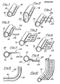
- they are constituted by a drawn tubolar element 10 with circular section or by a drawn tubular element 12 with oval section directly obtained with a protruding side fin 14 or 16, which can be advantagously off centered with respect to the diameter 18 or to the transversal axis 20 of the section, to which said fin 14 or 16 is parallel.
- the tubular elements can be obtained without difficulty for instance by cold drawing and have only slightly higher manufacturing cost than tubes without fin 14 or 16, but they give, as it will be seen, advantages which widely compensate this slighthly higher cost.
- FIGs 3,4,5 and 6 illustrate the welding operation of different bearing or supporting elements to tubes 1 0 of the type illustrated in figure 1.
- the fin 14 is placed in the upper position, namely towards the position at sight of the piece or component of furniture.
- the grating 22 is welded with the ends of its transversal rods 24 in correspondence to the upper surface of the fin 14, said welding being performed in a way known in itself by projection.
- the tubular component 10 is positioned to get its fin 14 to be oriented in the lower part of same, that is in the part oppostie to the part of the product at sight.
- tubular bodies 26 are fixed to the upper surface of the fin 14 said tubular bodies 26 being on their turn designed to support a covering element, for instance made of plastic material, which is fastened to the tubular bodies 26 and fills the plane defined by said latter bodies and the plane tangent upside to the tube 10.
- a covering element for instance made of plastic material
- the tubular element 10 positioned for instance with its fin 1 4 in the upper part, is coupled to a plate 28 with possible holes 30.
- the plate 28 can be welded by projection in the upper part or in the lower part of the fin 1 4, as illustrated in figures 5 ahd 6 respectively.
- the first configuration allows better resistance to static stress exercised from upside down, while the second configuration resists to stress exercised from down upwards and if part at sight of the furnishing component is the upper one, a better outward aspect of the product is obtained in case the holes 30 are on the terminal area of the plate 28.
- the tubular component 10 presents its fin 14 fixed to the rods 24 or to the plate 28, or to the tubular bodies 26 respectively.
- the immersion of the previously heated product into powdered plastic material allows to apply a plastic layer 3 2 which completely and safely covers the whole welded joint, as the powder easily penetrates into the gaps between the welded parts.
- the reciprocal disposition of the fins 14 and bearing or supporting element welded to said fins is such that the stress exercised on the latter is discharged on the fin 14, and actions of reciprocal I separation between the welded parts are not exercised.
- This advantage positively affects not only the static resistance of the product, but also and above all the finishing of same, in that the protective superficial layer 32 of plastic material is capable of perfectly resisting to the stress usually exercised on the product without cracking and therefore without allowing oxidation to begin.
- figure 10 schematically illustrates a corner of a chair, in which the tubular frame has been bent as previously said, together with the plate 28.
- This product like the other, ones can be completed with the application of other elements, in part i cu I ar other elements of the frame which, not requiring a projection welding to parts of the supporting elements, can have a simple tubular configuration.
Landscapes
- Engineering & Computer Science (AREA)
- Mechanical Engineering (AREA)
- Furniture Connections (AREA)
Applications Claiming Priority (2)
| Application Number | Priority Date | Filing Date | Title |
|---|---|---|---|
| IT2566681 | 1981-12-18 | ||
| IT25666/81A IT1140358B (it) | 1981-12-18 | 1981-12-18 | Procedimento per la fabbricazione di mobili metallici e mobili cosi' ottenuti |
Publications (1)
| Publication Number | Publication Date |
|---|---|
| EP0082308A1 true EP0082308A1 (fr) | 1983-06-29 |
Family
ID=11217405
Family Applications (1)
| Application Number | Title | Priority Date | Filing Date |
|---|---|---|---|
| EP82110645A Withdrawn EP0082308A1 (fr) | 1981-12-18 | 1982-11-18 | Procédé de fabrication de meubles métalliques et meubles ainsi obtenus |
Country Status (2)
| Country | Link |
|---|---|
| EP (1) | EP0082308A1 (fr) |
| IT (1) | IT1140358B (fr) |
Cited By (1)
| Publication number | Priority date | Publication date | Assignee | Title |
|---|---|---|---|---|
| NL1004470C2 (nl) * | 1996-11-07 | 1998-05-19 | Leer Koninklijke Emballage | Buis. |
Citations (4)
| Publication number | Priority date | Publication date | Assignee | Title |
|---|---|---|---|---|
| GB711614A (en) * | 1951-08-17 | 1954-07-07 | Jan Van Schothorst | Improvements in and relating to electrical pressure welding of tire rims |
| FR1139189A (fr) * | 1955-01-04 | 1957-06-26 | Procédé pour exécuter un joint par soudage électrique | |
| FR1298377A (fr) * | 1961-05-29 | 1962-07-13 | Peugeot Cycles | Procédé d'assemblage par soudure électrique et ouvrages en résultant |
| DE2645239A1 (de) * | 1975-10-07 | 1977-04-21 | Us Commerce | Vorrichtung und verfahren zum ueberwachen der optischen strahlung einer quelle |
-
1981
- 1981-12-18 IT IT25666/81A patent/IT1140358B/it active
-
1982
- 1982-11-18 EP EP82110645A patent/EP0082308A1/fr not_active Withdrawn
Patent Citations (4)
| Publication number | Priority date | Publication date | Assignee | Title |
|---|---|---|---|---|
| GB711614A (en) * | 1951-08-17 | 1954-07-07 | Jan Van Schothorst | Improvements in and relating to electrical pressure welding of tire rims |
| FR1139189A (fr) * | 1955-01-04 | 1957-06-26 | Procédé pour exécuter un joint par soudage électrique | |
| FR1298377A (fr) * | 1961-05-29 | 1962-07-13 | Peugeot Cycles | Procédé d'assemblage par soudure électrique et ouvrages en résultant |
| DE2645239A1 (de) * | 1975-10-07 | 1977-04-21 | Us Commerce | Vorrichtung und verfahren zum ueberwachen der optischen strahlung einer quelle |
Cited By (1)
| Publication number | Priority date | Publication date | Assignee | Title |
|---|---|---|---|---|
| NL1004470C2 (nl) * | 1996-11-07 | 1998-05-19 | Leer Koninklijke Emballage | Buis. |
Also Published As
| Publication number | Publication date |
|---|---|
| IT8125666A0 (it) | 1981-12-18 |
| IT1140358B (it) | 1986-09-24 |
Similar Documents
| Publication | Publication Date | Title |
|---|---|---|
| DE69505569T2 (de) | Kochgefäss mit verstärktem Boden und dessen Herstellung | |
| DE4031173A1 (de) | Verfahren zum herstellen von turbinenscheiben aus zwei legierungen | |
| US2451099A (en) | Method of uniting metal pieces by means of a bonding layer of predetermined thickness | |
| EP0525453B1 (fr) | Procédé de fabrication d'un récipient de cuisson | |
| DE2543970A1 (de) | Vorformung eines verkleidungsbleches fuer ein konvex-konkaves substrat | |
| DE3327476C2 (fr) | ||
| DE2226317A1 (de) | Drehbares potentiometer-bauelement und zugehoeriges herstellungsverfahren | |
| EP1654089B1 (fr) | Procede pour produire des rotors de turbine a gaz a aubage integral par soudage par decharge de condensateur | |
| DE60224256T2 (de) | Reibungschweissen eines Verstärkungselementes auf einem dünnwandigen Element mit einem zwischengelegten Schichtelement | |
| US4980245A (en) | Multi-element metallic composite article | |
| DD247863A5 (de) | Verfahren zur herstellung von doppelschichtigen boeden mit ausfuellung des hohlraumes | |
| US2125211A (en) | Method of producing a staple strip | |
| US4785988A (en) | Attachment of lead to elongated conductor | |
| US2799840A (en) | Terminal construction | |
| US2286047A (en) | Cutting implement | |
| DE1464548A1 (de) | Elektrische Bimetallkontakte | |
| CA1075376A (fr) | Support faconne par extrusion en deux etapes | |
| US2231450A (en) | Method of forming a gridlike structure | |
| DE4125114C1 (fr) | ||
| DE69103695T2 (de) | Montageverfahren einer Radscheibe an eine Felge und ein so erhaltenes Fahrzeugrad. | |
| DE4419652A1 (de) | Plattenförmiges Formelement | |
| JPH08187513A (ja) | アルミニウム板のv曲げ加工法及びその工具 | |
| EP0752295A1 (fr) | Procédé, outil poinçon-matrice et son utilisation pour la fabrication de casseroles et poêles | |
| JPH02227919A (ja) | リベット型接点 | |
| DE853242C (de) | Mit einer Tuelle versehenes Kochgefaess und Verfahren zu seiner Herstellung |
Legal Events
| Date | Code | Title | Description |
|---|---|---|---|
| PUAI | Public reference made under article 153(3) epc to a published international application that has entered the european phase |
Free format text: ORIGINAL CODE: 0009012 |
|
| AK | Designated contracting states |
Designated state(s): AT BE CH DE FR GB LI NL SE |
|
| 17P | Request for examination filed |
Effective date: 19831214 |
|
| STAA | Information on the status of an ep patent application or granted ep patent |
Free format text: STATUS: THE APPLICATION HAS BEEN WITHDRAWN |
|
| 18W | Application withdrawn |
Withdrawal date: 19860127 |
|
| RIN1 | Information on inventor provided before grant (corrected) |
Inventor name: BISCARINI, ALDO |