EP0082430A2 - Verfahren und Vorrichtung zur Kopplung von optischen Fasern - Google Patents
Verfahren und Vorrichtung zur Kopplung von optischen Fasern Download PDFInfo
- Publication number
- EP0082430A2 EP0082430A2 EP82111425A EP82111425A EP0082430A2 EP 0082430 A2 EP0082430 A2 EP 0082430A2 EP 82111425 A EP82111425 A EP 82111425A EP 82111425 A EP82111425 A EP 82111425A EP 0082430 A2 EP0082430 A2 EP 0082430A2
- Authority
- EP
- European Patent Office
- Prior art keywords
- fibers
- pair
- elements
- fiber
- signal
- Prior art date
- Legal status (The legal status is an assumption and is not a legal conclusion. Google has not performed a legal analysis and makes no representation as to the accuracy of the status listed.)
- Granted
Links
- 239000000835 fiber Substances 0.000 title claims abstract description 103
- 238000010168 coupling process Methods 0.000 title claims abstract description 30
- 230000008878 coupling Effects 0.000 title claims abstract description 29
- 238000005859 coupling reaction Methods 0.000 title claims abstract description 29
- 238000000034 method Methods 0.000 title claims abstract description 12
- 239000013307 optical fiber Substances 0.000 claims abstract description 22
- 230000003287 optical effect Effects 0.000 claims description 13
- 230000000694 effects Effects 0.000 description 2
- CNQCVBJFEGMYDW-UHFFFAOYSA-N lawrencium atom Chemical compound [Lr] CNQCVBJFEGMYDW-UHFFFAOYSA-N 0.000 description 2
- ORQBXQOJMQIAOY-UHFFFAOYSA-N nobelium Chemical compound [No] ORQBXQOJMQIAOY-UHFFFAOYSA-N 0.000 description 2
- 238000010276 construction Methods 0.000 description 1
- 230000007812 deficiency Effects 0.000 description 1
- 238000005516 engineering process Methods 0.000 description 1
- 239000000463 material Substances 0.000 description 1
- 238000003825 pressing Methods 0.000 description 1
Images

Classifications
-
- G—PHYSICS
- G02—OPTICS
- G02B—OPTICAL ELEMENTS, SYSTEMS OR APPARATUS
- G02B6/00—Light guides; Structural details of arrangements comprising light guides and other optical elements, e.g. couplings
- G02B6/24—Coupling light guides
- G02B6/26—Optical coupling means
- G02B6/28—Optical coupling means having data bus means, i.e. plural waveguides interconnected and providing an inherently bidirectional system by mixing and splitting signals
- G02B6/2804—Optical coupling means having data bus means, i.e. plural waveguides interconnected and providing an inherently bidirectional system by mixing and splitting signals forming multipart couplers without wavelength selective elements, e.g. "T" couplers, star couplers
- G02B6/2821—Optical coupling means having data bus means, i.e. plural waveguides interconnected and providing an inherently bidirectional system by mixing and splitting signals forming multipart couplers without wavelength selective elements, e.g. "T" couplers, star couplers using lateral coupling between contiguous fibres to split or combine optical signals
-
- Y—GENERAL TAGGING OF NEW TECHNOLOGICAL DEVELOPMENTS; GENERAL TAGGING OF CROSS-SECTIONAL TECHNOLOGIES SPANNING OVER SEVERAL SECTIONS OF THE IPC; TECHNICAL SUBJECTS COVERED BY FORMER USPC CROSS-REFERENCE ART COLLECTIONS [XRACs] AND DIGESTS
- Y10—TECHNICAL SUBJECTS COVERED BY FORMER USPC
- Y10S—TECHNICAL SUBJECTS COVERED BY FORMER USPC CROSS-REFERENCE ART COLLECTIONS [XRACs] AND DIGESTS
- Y10S359/00—Optical: systems and elements
- Y10S359/90—Methods
Definitions
- the present invention relates to a method for fiber optic coupling according to the preamble of claim 1 as well as to an apparatus for fiber optic coupling.
- couplers for accomplishing this function were sometimes referred to as "star couplers" which either connected the input and output fibers directly with a plurality of smaller cross section fibers, such as is shown in US-Patent 3 883 222 or which provided a mixing chamber, such as found in US-Patents 4 193 661, 4 245 884 and 4 262 995.
- Star couplers are a major economic portion of a fiber optic bus and for example in a bus system,the star coupler is multiple of the costs of the electronic components and of the fiber. With the evolution of fiber optic technology, the cost of cables, connectors and electronics is expected to decrease sharply causing considerable concern with respect to the cost of the star coupler.
- the present invention comprises dividing the input optical fibers into pairs of fibers and joining the two fibers in each pair together, such as by fusing,to form a number of junction points at a first location.
- the joining of fibers along their length is a simple and inexpensive task such as is shown in US-Patent 4 054 366.
- the process of joining two fibers may be as simple as pressing them together in the presence of enough heat to melt the surface material so they become fused.
- a pair of hot tweezers may be used to press the fibers together or the fibers may be held together and exposed to heat from another source.
- coupling fibers in this manner allows any optical signal that exists in either of the two fibers of each pair prior to the junction to be divided so that a portion of that optical signal appears on both of the fibers after the junction.
- the number of junctions can be kept relatively small and still allow an optical signal from anyone of a plurality of input fibers to be spread out so that a portion of that signal is received at all of the output fibers.
- a symbolic star coupler is shown as a box 10 labelled S.C.
- Star coupler 10 is shown having four input fiber optic elements 12, 14, 16 and 18 receiving inputs from transmitters T 1 , T 2 , T3 ... T N respectively.
- Star coupler 10 is shown having four outputs 22, 24, 26 and 28 respectively from which four output signals to receivers R 1 , R 2 , R 3 ... R N emerge.
- the purpose of star coupler 10 is to take any input signal such as T 1 and make sure that a portion of that signal appears in each of the outputs R 1 , R2 , R 3 ... R N .
- star coupler 10 should be split by star coupler 10 so that a portion of these outputs also appear in R 1 , R 2 , R 3 ... R N .
- the star coupler 10 has heretofore been disproportionately expensive with respect to the fiber optics and other apparatus used in such optical systems.
- FIGURE 2 shows two fiber optic elements having input portions 30 and 32, a joined together portion 34, which may be accomplished by fusing or other common , techniques, and two output portions 36 and 38.
- An input signal P 1 is shown entering input portion 30 and an input signal P 2 is shown entering input portion 32.
- the two signals P 1 and P2 are combined in the junction section 34 as shown by arrows 40 and 42 so as to produce two output signals.
- the output signal from both outputs is shown to be the same, i.e., (P 1 +p 2 )/2 showing that the input signals have been evenly divided and that a portion of both signals at the inputs 30 and 32 now appear at the outputs 36 and 38.
- a fiber optic coupler may be fabricated in several ways.
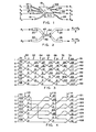
- FIGURE 3 shows schematically a fiber optic coupler having eight individual optical fiber elements 51-58.
- element 51 is shown having an input "1" while all of the other inputs are shown as "0". It will be understood, of course, that the size of the signal may be of any value and that signals may exist on any other input or on more than one of the inputs at any time.
- the fiber optic elements are arranged in pairs as, for example, elements 51 and 52 comprise a pair that are joined together at a junction like that shown in FIGURE 2 at a position shown as 60 in FIGURE 3.
- elements 53 and 54 form a pair with a junction at position 60
- elements 55 and 56 form a pair with a junction at location 60
- elements 57 and 58 form a pair with a junction at location 60. Since a "l" exists on fiber optic element 51 and "Os" exist on all of the other elements, the signals on elements 51 and 52 after the junction at location 60 are shown to be .5 each while the signals on the rest of the elements after the junction at location 60 are shown to be 0.
- elements 52 and 55 have a junction at position 62 and elements 56 and 57 have a junction at position 62.
- Fiber optic elements 51 and 58 continue past position 62 with no junction.
- elements 51 and 52 are again joined at a position 64 and similarly elements 53 and 54, elements 55 and 56, and elements 57 and 58 have junctions at position 64. It is seen that after position 64, the signal on element 1 has a value of .37 as does the signal on element 52 while the signal on elements 53 and 54 have a value of .12 and the remaining elements still have a signal of value 0.
- elements 52 and 53 are again joined together at a position 66 as are elements 54 and 55 and elements 56 and 57 with elements 51 and 58 continuing past position 66. Again, by virtue of the dividing of signals, the signal on element 51 will continue to be .37 but the signals on elements 52 and 53 will now be .25 and the signals on elements 54 and 55 will now be .06 while elements 56, 57 and 58 continue to have a 0.
- elements 52 and 53, elements 54 and 55, and elements 56 and 57 are again joined with elements 51 and 58 passing by position 70 without a junction.
- element 51 has a signal of value .31
- elements 52 and 53 have a signal of value .24
- elements 54 and 55 have a signal of value .1
- elements 56 and 57 have a signal of value .015
- element 58 continues to have a 0 signal.
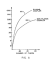
- the apparatus of FIGURE 3 has several undesirable features: first, a fairly large number of junctions are required (25) when eight fibers are used and second, the outputs 81-88 differ in magnitude from a value of .28 to a value of .007. When larger number of fibers are used, the number of junctions increases considerably and the size of the smaller signals becomes very small.
- FIGURE 3 may be referred to as a planar coupler and, referring to FIGURE 5 which shows the number of junctions compared with the number of fibers, it is seen that the curve identified by reference numeral 90 compares the number of fibers and the number of joints for a planar coupler.
- FIGURE 4 a preferred embodiment of the present invention proposes a coupling arrangement such as is shown schematically in FIGURE 4.
- FIGURE 4 again shows eight fiber optic elements, 101-108, respectively and, like in FIGURE 3, an input signal of value 1 is shown at the input of element 101 while the remaining elements have an input signal of value 0.
- the elements are gathered together in pairs with 101 being paired with 102, 103 being paired with 104, 105 being paired with 106, and 107 paired with 108 and then the pairs are joined at a first location 110 in a manner similar to that shown in FIGURE 3.
- the magnitude of the signals existing after the junctions at position 110 is again .5 for elements 101 and 102 and 0 for the remaining elements.
- the elements are again paired but in a manner substantially different from that shown in FIGURE 3.
- element 101 is paired with element 106
- element 103 is paired with element 108
- element 105 is paired with element 102
- element 107 is paired with element 104.
- the pairs are again joined at a position 112.
- four elements, 105, 102, 101 and 106 have a signal of value .25 after the junction at position 112 while elements 107, 104, 103 and 108 continue to have a 0 signal.
- FIGURE 4 may be referred to as a nonplanar coupler since it requires a cross over of fiber optic elements in various locations throughout the system.
- FIGURE 5 shows the comparison of the number of joints. required versus the number of fibers used for the nonplanar coupler along a curve identified by reference numeral 130. It is seen that as the number of fibers increases, the difference between the number of joints used for the nonplanar coupler becomes more and more significant with respect to the number of joints used with respect to the planar coupler.
- FIGURE 4 is shown to have eight fiber optic elements, the principles in the connections of joints with respect to various pairs can be applied to any number of elements.
- FIGURE 6 shows a 32 element system and the procedure by which they are joined in pairs and coupled.
- the 32 fiber optic elements are identified by lines 201-232.
- an X has been placed between any two fiber optic elements that are coupled together and it is therefore seen that elements 201 and 202 as well as elements 203 and 204, elements 205 and 206 ... elements 231 and 232 are coupled at a first position 240.
- Element 201 then is shown leading upwards and hooking downwardly to indicate that it traverses all of the other fiber optic elements and appears again at the bottom as element 201 and from thence upwardly at an angle where it is shown being paired with element 218.
- Element 203 in similar fashion is shown leading up to the right where it hooks downwardly and appears again at the bottom and then leads upward to the right where it is paired with element 220.
- elements 205, 207, 209, 211, 213 and 215 are shown moving up to the right hooking down, appearing at the bottom and moving up to the right to be paired with elements 222, 224, 226, 228, 230 and 232 respectively.
- Elements 217, 219, 221, 223, 225, 227, 229 and 231 are shown moving up to the right to be paired with elements 202, 204, 206, 208, 210, 212, 214 and 216 respectively.
- each of the elements in effect moves up 16 positions after the junctures at position 240 to be paired with a new element.
- the elements are again joined at a position shown as 242.
- the signals are combined at position 242
- all of the elements now move up eight positions in FIGURE 6 where they are again paired with a new element and then coupled at a position shown as 244.
- FIGURE 6 shows the arrangement of the various elements 201-232 after the pairings and junctures.
Landscapes
- Physics & Mathematics (AREA)
- General Physics & Mathematics (AREA)
- Optics & Photonics (AREA)
- Optical Couplings Of Light Guides (AREA)
- Optical Communication System (AREA)
- Mechanical Coupling Of Light Guides (AREA)
Applications Claiming Priority (2)
| Application Number | Priority Date | Filing Date | Title |
|---|---|---|---|
| US331865 | 1981-12-17 | ||
| US06/331,865 US4473271A (en) | 1981-12-17 | 1981-12-17 | Method and apparatus for fiber optic coupling |
Publications (3)
| Publication Number | Publication Date |
|---|---|
| EP0082430A2 true EP0082430A2 (de) | 1983-06-29 |
| EP0082430A3 EP0082430A3 (en) | 1986-06-11 |
| EP0082430B1 EP0082430B1 (de) | 1989-12-27 |
Family
ID=23295713
Family Applications (1)
| Application Number | Title | Priority Date | Filing Date |
|---|---|---|---|
| EP82111425A Expired EP0082430B1 (de) | 1981-12-17 | 1982-12-09 | Verfahren und Vorrichtung zur Kopplung von optischen Fasern |
Country Status (5)
| Country | Link |
|---|---|
| US (1) | US4473271A (de) |
| EP (1) | EP0082430B1 (de) |
| JP (2) | JPS58111012A (de) |
| CA (1) | CA1209833A (de) |
| DE (1) | DE3280073D1 (de) |
Cited By (1)
| Publication number | Priority date | Publication date | Assignee | Title |
|---|---|---|---|---|
| US4867519A (en) * | 1988-01-08 | 1989-09-19 | Societe Anonyme Dite: Alcatel Cit | N by N type optical diffuser and coupling network |
Families Citing this family (5)
| Publication number | Priority date | Publication date | Assignee | Title |
|---|---|---|---|---|
| US4728169A (en) * | 1981-04-27 | 1988-03-01 | Raychem Corp. | Methods and apparatus for optical fiber systems |
| US4588255A (en) * | 1982-06-21 | 1986-05-13 | The Board Of Trustees Of The Leland Stanford Junior University | Optical guided wave signal processor for matrix-vector multiplication and filtering |
| US4708424A (en) * | 1984-09-21 | 1987-11-24 | Northwestern University | Transmissive single-mode fiber optics star network |
| JPS63197195A (ja) * | 1987-02-10 | 1988-08-16 | Nec Corp | 光マトリクススイツチ |
| US5282257A (en) * | 1990-12-28 | 1994-01-25 | Fuji Xerox Co., Ltd. | Star coupler and optical communication network |
Family Cites Families (12)
| Publication number | Priority date | Publication date | Assignee | Title |
|---|---|---|---|---|
| US3571739A (en) * | 1968-10-18 | 1971-03-23 | Bell Telephone Labor Inc | Multimode hybrid-coupled fan-out and fan-in array |
| US3883222A (en) * | 1973-09-07 | 1975-05-13 | Corning Glass Works | Coupler for optical communication system |
| US3908121A (en) * | 1973-11-19 | 1975-09-23 | Gte Laboratories Inc | Integrated optical frequency-division multiplexer |
| GB1470539A (en) * | 1974-06-06 | 1977-04-14 | Standard Telephones Cables Ltd | Optical fibre optical power dividers |
| US4165225A (en) * | 1975-04-17 | 1979-08-21 | Siemens Aktiengesellschaft | Distributor for optical signals |
| US4120560A (en) * | 1975-06-09 | 1978-10-17 | Siemens Aktiengesellschaft | Optical waveguide network |
| US4054366A (en) * | 1976-07-12 | 1977-10-18 | Hughes Aircraft Company | Fiber optics access coupler |
| US4142775A (en) * | 1976-09-27 | 1979-03-06 | Bell Telephone Laboratories, Incorporated | Optical signal processing devices |
| FR2389150A1 (fr) * | 1977-04-29 | 1978-11-24 | Thomson Csf | Coupleur multivoies pour liaisons par fibres optiques |
| US4245884A (en) * | 1978-12-22 | 1981-01-20 | International Business Machines Corporation | Optical coupler for interconnecting two or more optical transmission lines |
| US4262995A (en) * | 1979-03-05 | 1981-04-21 | Hughes Aircraft Company | Planar star coupler device for fiber optics |
| US4262992A (en) * | 1979-04-18 | 1981-04-21 | The United States Of America As Represented By The Director Of The National Security Agency | Variable integrated optical logic element |
-
1981
- 1981-12-17 US US06/331,865 patent/US4473271A/en not_active Expired - Fee Related
-
1982
- 1982-12-01 CA CA000416758A patent/CA1209833A/en not_active Expired
- 1982-12-09 EP EP82111425A patent/EP0082430B1/de not_active Expired
- 1982-12-09 DE DE8282111425T patent/DE3280073D1/de not_active Expired - Fee Related
- 1982-12-17 JP JP57221749A patent/JPS58111012A/ja active Pending
-
1988
- 1988-11-02 JP JP1988142801U patent/JPH0177607U/ja active Pending
Cited By (1)
| Publication number | Priority date | Publication date | Assignee | Title |
|---|---|---|---|---|
| US4867519A (en) * | 1988-01-08 | 1989-09-19 | Societe Anonyme Dite: Alcatel Cit | N by N type optical diffuser and coupling network |
Also Published As
| Publication number | Publication date |
|---|---|
| DE3280073D1 (de) | 1990-02-01 |
| JPS58111012A (ja) | 1983-07-01 |
| US4473271A (en) | 1984-09-25 |
| JPH0177607U (de) | 1989-05-25 |
| CA1209833A (en) | 1986-08-19 |
| EP0082430A3 (en) | 1986-06-11 |
| EP0082430B1 (de) | 1989-12-27 |
Similar Documents
| Publication | Publication Date | Title |
|---|---|---|
| US3933455A (en) | Method for joining optical fibre bundles | |
| EP1279974A2 (de) | Y-verzweigter optischer Wellenleiter und diesen verwendender mehrstufiger optischer Leistungsteiler | |
| US4566753A (en) | Optical star coupler | |
| US4305641A (en) | Optical mixing element | |
| EP1380862A2 (de) | Optischer Leistungsteiler | |
| EP0082430A2 (de) | Verfahren und Vorrichtung zur Kopplung von optischen Fasern | |
| EP0625719A1 (de) | Polarisationsunabhängiger 2X2 Faserkoppler als Wellenlängen-Multiplexer | |
| US4966432A (en) | Optical coupler and process for preparation thereof | |
| EP0493132A1 (de) | Wellenleiterkoppler/-verzweiger | |
| JP2957055B2 (ja) | 光分岐結合器 | |
| US5539847A (en) | Integrated optical coupler with one input port and 2n output ports | |
| DE69633543T2 (de) | Netzknotenvorrichtung | |
| US20210033795A1 (en) | Fibre-optic cross-connection system | |
| US4675136A (en) | Process for the connection of optical fibres and connecting devices obtained according to this process | |
| JPS60200210A (ja) | 光結合器 | |
| US6431767B2 (en) | Method for producing a coupler based on fiber-fused connection | |
| SE442454B (sv) | Anslutningsdon | |
| DE2839428A1 (de) | Verfahren zur herstellung einer verzweigung zwischen lichtwellenleitern | |
| JPH0664215B2 (ja) | 単一モ−ド光フアイバの接続方法 | |
| JP2827215B2 (ja) | 導波路整合方式 | |
| JPS61113008A (ja) | 光分配回路およびその製造方法 | |
| JP2000088704A (ja) | 心線対照システムおよび心線対照方法 | |
| JPS63143507A (ja) | 多芯型光フアイバジヤンパ線とそれを用いた接続方法 | |
| JPS6120177B2 (de) | ||
| JPS6225006Y2 (de) |
Legal Events
| Date | Code | Title | Description |
|---|---|---|---|
| PUAI | Public reference made under article 153(3) epc to a published international application that has entered the european phase |
Free format text: ORIGINAL CODE: 0009012 |
|
| AK | Designated contracting states |
Designated state(s): DE FR GB |
|
| PUAL | Search report despatched |
Free format text: ORIGINAL CODE: 0009013 |
|
| AK | Designated contracting states |
Kind code of ref document: A3 Designated state(s): DE FR GB |
|
| 17P | Request for examination filed |
Effective date: 19861013 |
|
| 17Q | First examination report despatched |
Effective date: 19871204 |
|
| GRAA | (expected) grant |
Free format text: ORIGINAL CODE: 0009210 |
|
| AK | Designated contracting states |
Kind code of ref document: B1 Designated state(s): DE FR GB |
|
| REF | Corresponds to: |
Ref document number: 3280073 Country of ref document: DE Date of ref document: 19900201 |
|
| ET | Fr: translation filed | ||
| PLBE | No opposition filed within time limit |
Free format text: ORIGINAL CODE: 0009261 |
|
| STAA | Information on the status of an ep patent application or granted ep patent |
Free format text: STATUS: NO OPPOSITION FILED WITHIN TIME LIMIT |
|
| 26N | No opposition filed | ||
| PGFP | Annual fee paid to national office [announced via postgrant information from national office to epo] |
Ref country code: FR Payment date: 19920915 Year of fee payment: 11 |
|
| PGFP | Annual fee paid to national office [announced via postgrant information from national office to epo] |
Ref country code: DE Payment date: 19920921 Year of fee payment: 11 |
|
| PGFP | Annual fee paid to national office [announced via postgrant information from national office to epo] |
Ref country code: GB Payment date: 19920923 Year of fee payment: 11 |
|
| PG25 | Lapsed in a contracting state [announced via postgrant information from national office to epo] |
Ref country code: GB Effective date: 19931209 |
|
| GBPC | Gb: european patent ceased through non-payment of renewal fee |
Effective date: 19931209 |
|
| PG25 | Lapsed in a contracting state [announced via postgrant information from national office to epo] |
Ref country code: FR Effective date: 19940831 |
|
| PG25 | Lapsed in a contracting state [announced via postgrant information from national office to epo] |
Ref country code: DE Effective date: 19940901 |
|
| REG | Reference to a national code |
Ref country code: FR Ref legal event code: ST |