EP0082462A2 - Imprimante électrographique - Google Patents
Imprimante électrographique Download PDFInfo
- Publication number
- EP0082462A2 EP0082462A2 EP82111568A EP82111568A EP0082462A2 EP 0082462 A2 EP0082462 A2 EP 0082462A2 EP 82111568 A EP82111568 A EP 82111568A EP 82111568 A EP82111568 A EP 82111568A EP 0082462 A2 EP0082462 A2 EP 0082462A2
- Authority
- EP
- European Patent Office
- Prior art keywords
- print head
- cam
- printing unit
- cam follower
- carriage
- Prior art date
- Legal status (The legal status is an assumption and is not a legal conclusion. Google has not performed a legal analysis and makes no representation as to the accuracy of the status listed.)
- Granted
Links
Images

Classifications
-
- B—PERFORMING OPERATIONS; TRANSPORTING
- B41—PRINTING; LINING MACHINES; TYPEWRITERS; STAMPS
- B41J—TYPEWRITERS; SELECTIVE PRINTING MECHANISMS, i.e. MECHANISMS PRINTING OTHERWISE THAN FROM A FORME; CORRECTION OF TYPOGRAPHICAL ERRORS
- B41J2/00—Typewriters or selective printing mechanisms characterised by the printing or marking process for which they are designed
- B41J2/385—Typewriters or selective printing mechanisms characterised by the printing or marking process for which they are designed characterised by selective supply of electric current or selective application of magnetism to a printing or impression-transfer material
- B41J2/425—Typewriters or selective printing mechanisms characterised by the printing or marking process for which they are designed characterised by selective supply of electric current or selective application of magnetism to a printing or impression-transfer material for removing surface layer selectively from electro-sensitive material, e.g. metal coated paper
-
- B—PERFORMING OPERATIONS; TRANSPORTING
- B41—PRINTING; LINING MACHINES; TYPEWRITERS; STAMPS
- B41J—TYPEWRITERS; SELECTIVE PRINTING MECHANISMS, i.e. MECHANISMS PRINTING OTHERWISE THAN FROM A FORME; CORRECTION OF TYPOGRAPHICAL ERRORS
- B41J25/00—Actions or mechanisms not otherwise provided for
- B41J25/304—Bodily-movable mechanisms for print heads or carriages movable towards or from paper surface
- B41J25/312—Bodily-movable mechanisms for print heads or carriages movable towards or from paper surface with print pressure adjustment mechanisms, e.g. pressure-on-the paper mechanisms
Definitions
- the invention relates to an electrographic printing unit with a print head carriage which is longitudinally movable and pivotable on a guide rod parallel to the line and which can be pivoted with the print head from its raised position under spring force into the working position for contact with the recording medium.
- Printing units designed as matrix printers e.g. Thermal or electrographic printing units, also known as electroerosion printers, require direct contact between the print head and the recording medium for the duration of the generation of recording images, in particular characters, while at the beginning and end of the line the print head by a certain amount for the duration of the paper feed and the line switching of the paper is lifted off the record carrier.
- These movements for contacting or lifting off the recording medium are usually controlled electromagnetically in the known printing units.
- a thermal printing unit is described in US Pat. No. 3,509,980, in which the type carrier slide with the print head is mounted for longitudinal movement on a guide rod and an electromagnet rotates the guide rod, so that the print head rests on or is lifted off the recording medium.
- the electromagnet is arranged on the print head carriage and effects the pivoting movement of the print head relative to the print head carriage.
- US Pat. No. 4,225,251 shows a further printing unit design in which the print head is also pivotally mounted on the print head carriage, however, here the electromagnet is accommodated stationary in the machine frame and acts on the printhead via a rocker arm by lifting it from the recording medium against spring force.
- Another problem with the electromagnetic control of the print head movement for contacting and lifting off the recording medium is the heating of the drive when a large number of print lines are written in succession and the electromagnet is switched on and off at a high frequency for a correspondingly long time or is exposed to a correspondingly long duty cycle.
- the invention has for its object to develop a matrix printing unit of the type described in the introduction, which executes the movements of the print head for abutment on the recording medium and for lifting without an electromagnetic drive, namely using the print head carriage movements along the platen.
- This object has been achieved by the embodiment specified in claim 1.
- the printing unit according to the invention offers a number of advantages over the known printing unit designs.
- the invention avoids the sudden, jerky application or lifting of the print head caused by the electromagnetic control, but enables an optimal movement characteristic by appropriately designing the ramp areas of the cam surface, by accelerating and decelerating taking into account the speed requirements on the one hand and the stresses on the other cheapest values can be chosen freely.
- there is no control effort such as the photocell monitoring of the carriage movement according to US Pat. No. 4,225,251, and for the associated control logic for the electromagnet, so that a printing unit designed according to the invention can be produced at significantly lower costs and moreover requires practically no maintenance.
- a preferred embodiment according to the invention consists in that two independently following cam follower elements are arranged on the print head carriage and bear under the force of a spring on opposite sides of the cam rod.
- One surface is expediently designed as a cam surface and the other as a flat guide surface.
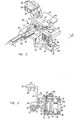
- the electrographic printing unit shown in FIG. 1 contains a print head carriage 10 which can be moved along a guide rod 11 which is arranged between the side frame parts 12 and 13.
- the movement of the print head carriage 10 on the guide rod 11 is transmitted via a belt or rope 14, which is driven via a drive roller (not shown) guided in a console 15, driven by a reversible servo motor 16, and via a deflection roller 17, a cam drive pulley 18 and another Deflection roller 19 is guided on the opposite side of the printing unit.
- Metallized paper is introduced underneath paper guide rollers 20 and is gripped by transport rollers 21 when the platen roller 22 is stepped on.
- the cam drive disk 18 causes the cam 23a of a cam disk 23 which rotates with the cam drive disk 18 to rotate against a cam follower roller 24a which is arranged on an arm 24 which can be pivoted about a pin 25.
- the arm 24 carries a drive pawl 26 which engages in a ratchet wheel 27 and the write roller 22 advanced by one print line each.
- D ie.5perrklinke 28 acts here any reverse rotation of the counter S chreibwalze 22nd
- the cam 23a and the print head carriage 10 cooperate in such a way that each time the print head carriage 10 reaches the end of the line, a step change into the next print line is carried out.
- the cam disk 23 is rotated by a little more than one full revolution.
- An emitter disk 29 on the shaft of the servo motor 16, in cooperation with an optical scanning element 30, generates electrical signals which represent the respective position of the print head carriage 10 of the line.
- the impression on the metallized paper is carried out by electrodes 32 on the print head 33 mounted in the print head carriage 10 coming into contact with the paper on the platen roller 22 and being switched on, causing the metal to burn off on the corresponding area of paper, causing one below it color contrast layer is visible.
- the electrodes are arranged in a pair of rows offset from one another in the normal to the print head carriage feed movement and form the desired characters in the form of small eroded points during the transverse movement of the print head carriage 10.
- the print head 33 and the electrodes 32 are lifted off the paper, the line feed is carried out by means of the platen roller 22, the drive direction of the servo motor 16 is reversed and thus the print head carriage 10 is moved back in the opposite direction, the print head and the electrodes being lowered again .
- cam follower rollers 35 and 36 are arranged on cam follower arms 37 and 38, respectively, the rollers abutting a transversely extending cam rod 39.
- the cam surface 40 of the cam rod 39 is designed such that the cam follower arm 38 with the cam follower roller 36 releases the adjustment of the electrodes 32 towards the paper as soon as the print head carriage 10 leaves the edge region.
- the position of the ramp area 41 near the left edge and the ramp area 42 near the right edge of the paper is decisive for the position at which this takes place.
- a carriage support 43 with a base plate 44 with a guide bore 45, through which the guide rod 11 protrudes and enables the longitudinal and rotary movement of the print head carriage 10.
- the carriage carrier 43 also has carrier parts 46 and 47, on which the print head 33 or, by means of a clamp part 47a, flat cable 48 are guided.
- a cable holder 50 is attached to the slide carrier 43 by means of a pair of screws 49, each with a hook 51 at its ends, into which the cable 14 is suspended, by means of which the line-parallel actuating movements of the print head carriage 10 are transmitted on the guide rod 11.
- the base plate 44 also carries a pin 52 on which the upper cam follower arm 37 and the lower cam follower arm 38 are mounted.
- the cam follower rollers 35 and 36 are each guided by means of bearing axles 35a and 36a, which in turn are in corresponding recesses rest in the cam follower arms 37 and 38.
- a tension spring 53 stretched between bolts 54 pulls the two cam follower arms 37 and 38 towards one another and thus causes the associated cam follower rollers 35 and 36 on the upper guide surface 55 (FIG. 3) and the lower cam surface 40 (FIGS. 1 and 3) of the cam rod 39 concerns.
- a retaining bolt 56 each with a collar at its ends, is arranged between the upper surface of the carrier part 47 and the lower surface of the cam follower arm 38 in such a way that it determines the maximum distance between these two elements.
- a compression spring 58 held in its axial position by means of centering rings 59 causes the carrier part 47 and thus the slide carrier 43 to be pushed away from the cam follower arm 38 up to the distance determined by the retaining bolt 56, while at the same time a pivoting movement of the slide carrier 43 in the clockwise direction, that is to say in the direction to the cam follower arm 38, is possible.
- the compression spring 58 has the function of limiting and determining the force with which the electrodes 32 are pressed against the paper.
- the print head carriage .10 performs an adjustment movement along the print line
- the upper cam follower arm 37 lies with its cam follower roller 35 on the upper guide surface 55 of the cam rod 39, the upper guide surface 55, as can be seen in FIG. 1, over the entire length of the Cam rod 39 runs evenly, ie in one plane.
- the lower cam follower arm 38 with its cam follower roller 36 passes through the ramp areas 41 and 42, in the sequence thereof it is pivoted slightly downwards in the areas near the line ends.
- the tension spring 53 causes a certain upward pivoting movement of the cam follower arm 38 under the control of the ramp area 41 or 42. This simultaneously raises the retaining pin 56 and below As a result of the action of the compression spring 58, the slide carrier 43 executes a counterclockwise pivoting movement with the print head 33 (FIGS. 2 and 3), the electrodes 32 coming into contact with the paper. During the subsequent impression process, the retaining bolt 56 is thus ineffective since the slide carrier 43 and the lower cam follower arm 38 are held in their relative position to one another by the forces of the tension spring 53 and the compression spring 58 acting in the opposite direction, the tension spring 53 naturally exerting the greater force .
- the compression spring 58 not only determines, as already mentioned, the force with which the electrodes 32 are pressed onto the paper during the printing process, but also inaccuracies in the electrode spacing in the course of the line movement and manufacturing tolerances within the elements involved compensates.
- the cam follower arms 37 and 38 are in the embodiment shown around that located in the base plate 44 Pin 52 rotatably mounted. Instead, they can also be arranged pivotably about the guide rod 11 or around cylindrical guide elements on the base plate 44 concentrically with the guide bore 45. In the previous embodiment, however, the sliding friction on the guide rod 11 would be increased.
- An embodiment is also conceivable in which the effective cam surface, that is to say the ramp regions 41 and 42, are arranged on the underside of the cam rod 39 on the upper surface thereof instead of on the cam surface 40.
- the slide carrier 43 would be pivotally mounted on the upper cam follower arm 37, so that the carrier part 47 now follows the pivoting movements of the upper cam follower arm 37.
- the compression spring 58 also determines the contact force of the electrodes 32, but care must be taken to ensure that there is a sufficient distance between the upper cam follower arm 37 and the carrier part 47.
Landscapes
- Common Mechanisms (AREA)
- Electronic Switches (AREA)
- Character Spaces And Line Spaces In Printers (AREA)
Applications Claiming Priority (2)
| Application Number | Priority Date | Filing Date | Title |
|---|---|---|---|
| US332799 | 1981-12-21 | ||
| US06/332,799 US4397576A (en) | 1981-12-21 | 1981-12-21 | Print head actuator |
Publications (3)
| Publication Number | Publication Date |
|---|---|
| EP0082462A2 true EP0082462A2 (fr) | 1983-06-29 |
| EP0082462A3 EP0082462A3 (en) | 1985-10-16 |
| EP0082462B1 EP0082462B1 (fr) | 1988-10-26 |
Family
ID=23299905
Family Applications (1)
| Application Number | Title | Priority Date | Filing Date |
|---|---|---|---|
| EP82111568A Expired EP0082462B1 (fr) | 1981-12-21 | 1982-12-14 | Imprimante électrographique |
Country Status (5)
| Country | Link |
|---|---|
| US (1) | US4397576A (fr) |
| EP (1) | EP0082462B1 (fr) |
| JP (1) | JPS58107384A (fr) |
| CA (1) | CA1196815A (fr) |
| DE (1) | DE3279151D1 (fr) |
Families Citing this family (7)
| Publication number | Priority date | Publication date | Assignee | Title |
|---|---|---|---|---|
| US4658270A (en) * | 1983-07-27 | 1987-04-14 | Sharp Kabushiki Kaisha | Recording apparatus |
| JPH0694225B2 (ja) * | 1983-10-25 | 1994-11-24 | キヤノン株式会社 | サーマルプリント装置 |
| JPH01101178A (ja) * | 1987-10-14 | 1989-04-19 | Tokyo Electric Co Ltd | サーマル転写プリンタ |
| US5169247A (en) * | 1988-06-02 | 1992-12-08 | Canon Kabushiki Kaisha | Thermal printer with biaxial motor feed of the carriage and ribbon |
| US4874265A (en) * | 1988-06-14 | 1989-10-17 | Xerox Corporation | Impact mechanism for impact printer |
| JPH02137967A (ja) * | 1988-11-18 | 1990-05-28 | Seikosha Co Ltd | シリアルプリンタ |
| JPH02145375A (ja) * | 1988-11-28 | 1990-06-04 | Sony Corp | サーマルプリンタ |
Family Cites Families (6)
| Publication number | Priority date | Publication date | Assignee | Title |
|---|---|---|---|---|
| US2141975A (en) * | 1938-03-31 | 1938-12-27 | William G H Finch | Multiple stylus facsimile recorder |
| US3646570A (en) * | 1970-02-13 | 1972-02-29 | Scope Inc | Printing head mechanism |
| IT939793B (it) * | 1971-09-06 | 1973-02-10 | Olivetti & Co Spa | Dispositivo di scrittura per macchine calcolatrici elettroniche |
| US3845850A (en) * | 1973-02-22 | 1974-11-05 | Bowmar Instrument Corp | Thermal printer |
| DE2825761C2 (de) * | 1978-06-12 | 1982-05-13 | Siemens AG, 1000 Berlin und 8000 München | Anordnung zum Antrieb eines Druckerwagens in Fern- oder Datenschreibmaschinen |
| US4343012A (en) * | 1980-12-30 | 1982-08-03 | International Business Machines Corporation | Printer control circuit |
-
1981
- 1981-12-21 US US06/332,799 patent/US4397576A/en not_active Expired - Lifetime
-
1982
- 1982-09-08 JP JP57155305A patent/JPS58107384A/ja active Pending
- 1982-11-04 CA CA000414912A patent/CA1196815A/fr not_active Expired
- 1982-12-14 DE DE8282111568T patent/DE3279151D1/de not_active Expired
- 1982-12-14 EP EP82111568A patent/EP0082462B1/fr not_active Expired
Also Published As
| Publication number | Publication date |
|---|---|
| CA1196815A (fr) | 1985-11-19 |
| JPS58107384A (ja) | 1983-06-27 |
| DE3279151D1 (en) | 1988-12-01 |
| EP0082462A3 (en) | 1985-10-16 |
| US4397576A (en) | 1983-08-09 |
| EP0082462B1 (fr) | 1988-10-26 |
Similar Documents
| Publication | Publication Date | Title |
|---|---|---|
| DE69117738T2 (de) | Schneidvorrichtung für Kurvenschreiber | |
| DE2535136C2 (de) | Halteeinrichtung in einer Druckvorrichtung zum Halten eines Einzelblattes oder eines einen Buchrücken aufweisenden Aufzeichnungsmediums | |
| DE3346523C2 (de) | Vorrichtung zum Zusammenbau eines Kraftfahrzeug-Körpers | |
| DE2239117C3 (de) | Verstellvorrichtung zum Verändern des Abstandes zwischen Druckkopf und Druckwiderlager | |
| DE69529925T2 (de) | Drucker | |
| DE2226394C3 (de) | Schnelldrucker | |
| DE2430407C3 (de) | Mosaik-Drahtdruckkopf | |
| DE3131750C2 (de) | Zuführrollenvorrichtung für eine Schreibmaschine | |
| DE1245627B (de) | Druckhammereinrichtung | |
| DE2919209C2 (de) | Steuervorrichtung für Schreibmaschinen | |
| EP0082462B1 (fr) | Imprimante électrographique | |
| DE3314252C2 (de) | Trommeldrucker | |
| DE2145245A1 (de) | Druckvorrichtung | |
| DE3329927C2 (fr) | ||
| DE2456275A1 (de) | Mechanische schreibvorrichtung | |
| DE69410875T2 (de) | Durch einzigen Motor betätigter Drucker mit Abtastkopf | |
| DE1262645B (de) | Rasterdrucker | |
| DE2110171A1 (de) | Hohenposittomerung fur Druck material eines Streifendruckers | |
| DE1561222B2 (de) | Druckvorrichtung für Fernschreiber, Schreibmaschinen u.dgl | |
| EP0064668B1 (fr) | Pivot pour mécanisme d'impression | |
| DE2635056C3 (de) | Druckvorrichtung zum Bedrucken, insbesondere Prägen von Karten o.dgl | |
| DE3101648C2 (de) | Papiervorschubeinrichtung | |
| EP0315818B1 (fr) | Machine pour impression sérigraphique | |
| DE2445279C3 (de) | Druckvorrichtung mit mehreren elektromechanisch in die gewünschte Druckstellung einstellbaren kreisscheibenförmigen Zeichenträgern | |
| DE3019773A1 (de) | Drucker zur herstellung eines rasterfoermig aufgebauten zeichens |
Legal Events
| Date | Code | Title | Description |
|---|---|---|---|
| PUAI | Public reference made under article 153(3) epc to a published international application that has entered the european phase |
Free format text: ORIGINAL CODE: 0009012 |
|
| AK | Designated contracting states |
Designated state(s): DE FR GB IT |
|
| 17P | Request for examination filed |
Effective date: 19831021 |
|
| PUAL | Search report despatched |
Free format text: ORIGINAL CODE: 0009013 |
|
| AK | Designated contracting states |
Designated state(s): DE FR GB IT |
|
| 17Q | First examination report despatched |
Effective date: 19870511 |
|
| GRAA | (expected) grant |
Free format text: ORIGINAL CODE: 0009210 |
|
| AK | Designated contracting states |
Kind code of ref document: B1 Designated state(s): DE FR GB IT |
|
| PG25 | Lapsed in a contracting state [announced via postgrant information from national office to epo] |
Ref country code: IT Free format text: LAPSE BECAUSE OF FAILURE TO SUBMIT A TRANSLATION OF THE DESCRIPTION OR TO PAY THE FEE WITHIN THE PRESCRIBED TIME-LIMIT;WARNING: LAPSES OF ITALIAN PATENTS WITH EFFECTIVE DATE BEFORE 2007 MAY HAVE OCCURRED AT ANY TIME BEFORE 2007. THE CORRECT EFFECTIVE DATE MAY BE DIFFERENT FROM THE ONE RECORDED. Effective date: 19881026 |
|
| GBT | Gb: translation of ep patent filed (gb section 77(6)(a)/1977) | ||
| REF | Corresponds to: |
Ref document number: 3279151 Country of ref document: DE Date of ref document: 19881201 |
|
| ET | Fr: translation filed | ||
| R20 | Corrections of a patent specification |
Effective date: 19881128 |
|
| PLBE | No opposition filed within time limit |
Free format text: ORIGINAL CODE: 0009261 |
|
| STAA | Information on the status of an ep patent application or granted ep patent |
Free format text: STATUS: NO OPPOSITION FILED WITHIN TIME LIMIT |
|
| 26N | No opposition filed | ||
| PG25 | Lapsed in a contracting state [announced via postgrant information from national office to epo] |
Ref country code: FR Effective date: 19900831 |
|
| REG | Reference to a national code |
Ref country code: FR Ref legal event code: ST |
|
| PGFP | Annual fee paid to national office [announced via postgrant information from national office to epo] |
Ref country code: GB Payment date: 19951127 Year of fee payment: 14 |
|
| PGFP | Annual fee paid to national office [announced via postgrant information from national office to epo] |
Ref country code: DE Payment date: 19951229 Year of fee payment: 14 |
|
| PG25 | Lapsed in a contracting state [announced via postgrant information from national office to epo] |
Ref country code: GB Effective date: 19961214 |
|
| GBPC | Gb: european patent ceased through non-payment of renewal fee |
Effective date: 19961214 |
|
| PG25 | Lapsed in a contracting state [announced via postgrant information from national office to epo] |
Ref country code: DE Effective date: 19970902 |