EP0082687A2 - Eisenbahnsignalempfänger - Google Patents
Eisenbahnsignalempfänger Download PDFInfo
- Publication number
- EP0082687A2 EP0082687A2 EP82306741A EP82306741A EP0082687A2 EP 0082687 A2 EP0082687 A2 EP 0082687A2 EP 82306741 A EP82306741 A EP 82306741A EP 82306741 A EP82306741 A EP 82306741A EP 0082687 A2 EP0082687 A2 EP 0082687A2
- Authority
- EP
- European Patent Office
- Prior art keywords
- signal
- receiver
- frequency
- transformation
- carrier
- Prior art date
- Legal status (The legal status is an assumption and is not a legal conclusion. Google has not performed a legal analysis and makes no representation as to the accuracy of the status listed.)
- Granted
Links
Images


Classifications
-
- G—PHYSICS
- G06—COMPUTING OR CALCULATING; COUNTING
- G06F—ELECTRIC DIGITAL DATA PROCESSING
- G06F17/00—Digital computing or data processing equipment or methods, specially adapted for specific functions
- G06F17/10—Complex mathematical operations
- G06F17/14—Fourier, Walsh or analogous domain transformations, e.g. Laplace, Hilbert, Karhunen-Loeve, transforms
- G06F17/141—Discrete Fourier transforms
-
- B—PERFORMING OPERATIONS; TRANSPORTING
- B61—RAILWAYS
- B61L—GUIDING RAILWAY TRAFFIC; ENSURING THE SAFETY OF RAILWAY TRAFFIC
- B61L23/00—Control, warning or like safety means along the route or between vehicles or trains
- B61L23/08—Control, warning or like safety means along the route or between vehicles or trains for controlling traffic in one direction only
- B61L23/14—Control, warning or like safety means along the route or between vehicles or trains for controlling traffic in one direction only automatically operated
- B61L23/16—Track circuits specially adapted for section blocking
- B61L23/166—Track circuits specially adapted for section blocking using alternating current
-
- H—ELECTRICITY
- H04—ELECTRIC COMMUNICATION TECHNIQUE
- H04L—TRANSMISSION OF DIGITAL INFORMATION, e.g. TELEGRAPHIC COMMUNICATION
- H04L27/00—Modulated-carrier systems
- H04L27/26—Systems using multi-frequency codes
Definitions
- the present invention relates to a railway signalling receiver for electrical signals carried by railway lines, which receiver performs a discrete Fourier transform.
- a receiver is useful, for example, for track circuit signals utilised for determining the presence and location of trains and automatic train protection systems which relay safe maximum speed information to moving trains.
- Discrete Fourier Transform techniques provide a quantitative analysis of the frequency spectrum of signal by sampling the signal in the time domain and transforming those time-domain samples into the frequency domain. The process involves the collection of a set of time domain data samples which form an initial set of data points, a multiplicity of elementary calculations are then carried out to produce a new set of intermediate results and proceeding through a series of levels or iterations to a final new set of outputs results in the frequency . domain.
- the initial set of data samples have real values in the time domain and the final set of results have real values in the frequency domain although the intermediate results may well be complex. However there is a substantial amount of redundancy among these intermediate terms due to the periodicity exhibited by the exponential function in the transform equation.
- the Winogrand algorithm is one, another is the Cooley-Tukey algorithm and another is Bergland's algorithm, which is a modification based on the Cooley-Tukey, and with which the particular examples described below will be concerned.
- Objects of the present invention include providing equipment which in addition to overcoming these difficulties is useful in different systems with different operating parameters but requires minimum modification and is useful as the basis of equipment for different purposes to which specialised peripheral items may be connected.
- ⁇ railway signalling receiver for electrical signals carried by railway lines comprising sensing means co-operating with the railway lines to sense the signals, sampling means operative in the time domain to continuously sample a sensed signal, data memory means for storing a plurality of sample values, means for performing a discrete Fourier transform on said stored sample values, data memory means for storing the results of the transformation and, means responsive to the final results of the transformation in the frequency domain to identify the sensed signal.
- a low-pass filter means is arranged to pass the difference frequency components and to exclude the sum frequency components in the heterodyned output which is connected to the means for performing a discrete Fourier transform on said difference frequency components.
- a combination of alternative carrier frequencies are employed as an identification signal by the associated track circuit transmitter thus defining between them the track section.
- the modulation frequency may be employed as an additional identification further increasing the number of possible track circuit identifying combinations or, as a means of encoding, for example, a maximum speed limit for transmission to a train in the track section.
- a carrier signal is modulated by a speed limit designating signal and is communicated to a train, on board the train the signal is sensed and sampled, the sample values are temporarily stored and used as input values for a discrete Fourier transform process, the final results of which yield, inter alia, the modulation frequency which indicates a speed limit.
- the present invention utilizes one of the most efficient discrete Fourier transform algorithms so far proposed, i.e. that by Cooley and Tukey which can be found published in "Mathematical Computing 19 (April 1965).”
- a further refinement of this algorithm which has been found particularly useful with real-valued series was subsequently described by Bergland in "Communications of the ACM (Vol. 11, No. 10 October 1968).”
- the algorithm takes as an initial input a real-valued time series comprising the N discrete sample values and, through a series of iterations which makes repeated use of a standardised calculation, computes the real and imaginary parts of the final Fourier coefficients of ( N ) frequency terms.
- Full theoretical descriptions of these algorithms can be found elsewhere, as noted above, and reference should be had to these publications for rigorous exposition of the theoretical basis of the algorithms.
- the process of evaluating the Discrete Fourier Transform according to the Cooley-Tukey algorithm involves setting-up an initial array of data points, in time sequential or natural order. The algorithm then proceeds to calculate successive arrays in a series of iterations until eventually the final level array is obtained in which the calculated frequency domain results are in a scrambled order. All of the intermediate data calculated for the intermediate iteration and final arrays are the result of computations using only two data values from the previous array.
- the operation to simultaneously calculate two data points in one level array from two "butterfly" operation have the corresponding array locations as the input data points and as each is only used once it is convenient to write the results back into the same memory address locations thus, saving greatly on memory size. It is not intended to give further or more detailed mathematical analysis of Fast Fourier Transforms here but, the manner in which these basic tools are adapted and applied in practical use in embodiments of the invention will be described below.
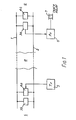
- FIG. 1 shows for a first example a schematic diagram of a jointless track circuit in which the running rails are referenced at 1 and 2 and track circuit receiver and transmitter transformers 3a and 4a, respectively, are connected between the rails 1, 2, at some distance apart, thereby defining the track section a monitored by the completed track circuit.
- Transformer units 3b and 4c which form part of the track circuits of track sections b and c on either side of track section a, are connected adjacent transformers 4a and 3a, respectively, at a relatively short distance therefrom.
- the theory and practical design and positioning of these track circuit transformers is well-understood in the art and for present purposes the units referred to will be assumed to be according to the prior art.
- the transmitted signal comprises a Frequency Shift-Keyed (FSK) signal employing up to four carrier frequencies at 1700, 2000, 2300 and 2600 Hz. with up- to ten low frequency modulation rates, in this example there are three modulation rates at 12.5, 15.0 and 20.0 Hz.
- the chosen combination of keyed carrier frequencies identify a particular track section/circuit, that is, a particular pair of track circuit transmitters and receivers is arranged to operate with a particular combination of carrier frequencies. This does not permit a large number of track circuit identifications, but does ensure that two track sections having the same identification are sufficiently far apart to prevent any possibility of the receiver in one section "picking-up" and positively responding to the transmitter in another and wrong section.
- the transmitter 5 feeding into the track section through transformer 4a in Fig. 1, may thus be of such known type according to the prior art and will not be further described.
- the transformer 3a feeds the FSK signal into a track circuit receiver 6 which "detects" the signal in a safe manner and energises track section relay 7 providing the signal is present and correct.
- Fig. 2 shows in block diagram form the hardware of the track circuit receiver 6 comprising at 11 a pair of analogue input terminals to which the received track circuit signal is connected.
- the input signal path feeds through a noise and overload protection circuit 12 through an anti-alias filter 13 comprising a low-pass analogue filter, the object of which is to eliminate signals above half the Nyquist frequency of fs/2.
- anti-alias filter 13 has a flat transfer characteristic from DC to 2 KHz which then falls by more than -30 dB at 5 kHz so that no signals above half the sampling frequency will be detected.
- the input signal is then fed to a sample and hold circuit 14, operated by a sample control signal on line 15, for sampling in the time domain at a frequency of 9.6 kHz.
- Sampled values are then digitised by an 8-bit analogue to digital converter 16.
- the 8-bit binary output of the converter gives a lowest detectable amplitude of 1 th (or -42dB) of the highest amplitude, thus providing the receiver with its previously mentioned dynamic range of 42dB.
- Converter 16 generates eight parallel binary digital data bits at its output 17 which has to be "logged", i.e. temporarily stored, for later retrieval in preparation for evaluation of the FFT algorithm.
- the parallel data is received by digital input and address latch circuit 18 the output of which'feeds into an 8-bit parallel multiplexed data bus 19 which interconnects a microprocessor Central Processing Unit (CPU) 20 and various co-operating units (11, 12, 13, 14 and 17.)
- CPU Central Processing Unit
- RAM Random Access Memory
- the control program for controlling operation of the CPU 20 is stored in a Read Only Memory (ROM) 22.
- peripheral interface adaptors 23 and 24 Also connected to the data bus 19 are two peripheral interface adaptors 23 and 24, the former providing an interface with a "signed 2's Complement Multiplier" 25 which is used to perform multiplications at the command of CPU 20 during execution of the FFT algorithm.
- the interface 24 is that through which the final digital output is delivered.
- the operating frequency of the CPU is derived from a crystal oscillator 26 resonant at 6.147 MHz.
- the timing signals which control operation and synchronisation of all the co-operating units is provided by timer 27 via the multiplexed databus 29. This also controls operation of the sample and hold circuit 24 through control signal 25 and also operation of the A to D converter 26 and address latch 28.
- control program stored in ROM 22 is directly written as a set of program instructions in "machine code" thus making it possible for the programmer to compose the program instructions so as to execute the FFT algorithm in the most efficient way possible having regard for the capabilities and restrictions of the particular microprocessor.
- the programmable read-only memory 22 contains a set of digital instructions specifically adapted to control the microprocessor in a sequence of operations which, when taken as a whole and in sequence, implement a discrete Fourier transform on the analogue input signal 11.
- the digitised waveform samples are stored and used as data-points in an initial level of calculations, the results of these calculations then form the data-points for a further level of calculations. This process is repeated several times through a succession of intermediate levels of calculation which descend to the final set of results in the completed transformation. As the initial samples and each level of results are only used in the next level of calculations, only one memory, 21, is used as temporary storage which need only be large enough to store the largest amount of data produced in any one level. Thus, data is discarded when no longer further required. Finally, the final results of the discrete Fourier transform are read-out through output circuits, generally referenced at 24.
- the discrete Fourier transform effectively produces, as a final result, a digitised spectrum analysis of the received input waveform 11.
- the final set of output data points represents a measure of the component frequencies of adjacent "frequency bins" spanning a frequency spectrum starting at O Hz.
- the required signal detection is achieved by monitoring or applying a discrimination function to the appropriate frequency bin.
- the lowest frequency component in the output results of a Fourier transform has to be zero Hertz.
- For the detection of FSK signals the need to detect a relatively high frequency has thus required a large number of samples and very long computation times in order to achieve adequate frequency resolution. A smaller number of samples speeds-up the computations, * " but causes a consequent loss of frequency resolution.
- Fig. 3 shows a flow chart of the sequence of events in this operation.
- the "heterodyning" operation is carried out digitally by steps described below.
- the received track circuit signal is modulated by frequency shift-keying, therefore, it contains a band of frequencies centred about the carrier frequency fc.
- the input signal is passed through an input noise filter, of band-pass type, which has the effect of limiting the frequencies present to a well-defined band.
- a carrier frequency fc of nominally 1600 Hz. is keyed between 1600 Hz. + 10 Hz. at a modulation rate of 12.5 Hz., 15.0 Hz., or 20.0 Hz.
- the modulation index is less than 1
- Frequency resolution i.e.
- a digital heterodyning operation is accomplished by multiplying the sampled input waveform with a sampled equivalent of the local oscillator frequency.
- the sampled input signal can be digitally heterodyned merely by multiplying each sample by the appropriate co-efficient of the cosine waveform.
- a normalised waveform may be assumed for the simplest multiplication that is, the first sample is multiplied by +1, the second sample is set to zero, the third sample multiplied by -1, the fourth sample is set to zero, and the cycle is repeated again and again in that sequence.
- ASK Amplitude Shift Keyed
- the sideband vectors In the FSK signal the sideband vectors always produce a resultant orthogonal with respect to the carrier vector, in contrast, in the ASK signal, the sideband vectors produce a resultant in-phase or anti-phase with the carrier vector.
- the final results yielded by the Fourier analysis contain both phase and amplitude information for all frequency components.
- the angle of a sideband resultant vector can be calculated.
- the magnitude of the resultants are calculated from the final Fourier transform results; if the resultant is too small (so that errors are no longer insignificant), the results may be inverted and the "opposite" vector calculated;-. the angle information is calculated and a discrimination check applied to positively locate an FSK signal. If this check fails, then it is assumed that the received signal is ASK and the calculated information is rejected, that is, the track circuit receiver reacts as if no track circuit signal was received and the track relay is de-energised.
- the invention forms part of an Automatic Train Protection (hereinafter ATP) system which involves the transmission to a moving train of a frequency signal which represents a maximum safe speed limit, the comparison of the actual train speed with that limit and, if it is exceeded, automatic.operation of the train's brakes.
- Speed limit information is transmitted to the train by means of amplitude-modulated carrier signals in which the speed limit signals are used as carrier modulators.
- Prior art ATP systems have employed analogue filters for decoding the ATP signal but these require one filter for each frequency signal of interest.
- This embodiment of the inention is effectively an FFT digital filter of non-recursive type, i.e. it has an open loop design which processes only sampled values of an input waveform.
- the same FFT algorithm is used to process different frequency allocations in different ATP systems with only minor changes to the software.
- the digital filter hardware described below is suitable for quantity production.
- the same basic hardware illustrated in Fig. 2 is used with differences only in the software program contained in the Read only Memory 22.
- the ATP digital filter has to perform two functions, as outlined in the flow chart of Fig. 4. Firstly it . has to determine that a received carrier signal is within its permitted frequency band and above minimum threshold amplitude and, second that there is a code modulation signal present, it is above minimum threshold amplitude, what is its frequency and, that there is only one modulation signal present.
- the carrier signal has a frequency of 1953 Hz. and there are four alternative modulation codes as follows:
- a coded ATP signal will be received by the train; at some time in a continuous series of events the digital filter of Fig. 2 will commence an operational cycle.
- the received signal is sampled at the 9.6 KHz sampling frequency, the first 64 of these time domain samples are digitised by ADC 16 and saved in RAM 21.
- CPU 10 initiates execution of the 64 point FFT program stored in ROM 22.
- the digitised sample values are retrieved from RAM 21 and used in calculating intermediate results which are temporarily stored in the same memory locations in RAM 11.
- the final results are again temporarily stored in the same locations in preparation for retrieval by the output interface unit 24.
- Identification of both carrier and modulation frequency may be by means of sequential operations in which the first operation searches for the carrier and execution of the second operation to find the modulation frequency is subject to positive detection of the carrier.
- the two transform search operations may be performed simultaneously but the results are examined for the carrier first and only for the modulation frequency if successful.
- the frequency spectrum is also checked to determine if only one modulation code is present in the received signal. If two or more codes are detected a "mixed modulation" alarm is energised and the ATP system reacts in a fail-safe manner by adopting the lowest speed limit indicated by the detected codes or calling for the train to be halted.
Landscapes
- Engineering & Computer Science (AREA)
- Physics & Mathematics (AREA)
- General Physics & Mathematics (AREA)
- Mathematical Physics (AREA)
- Mathematical Optimization (AREA)
- Theoretical Computer Science (AREA)
- Data Mining & Analysis (AREA)
- Pure & Applied Mathematics (AREA)
- Computational Mathematics (AREA)
- Mathematical Analysis (AREA)
- Discrete Mathematics (AREA)
- Mechanical Engineering (AREA)
- Algebra (AREA)
- Signal Processing (AREA)
- Databases & Information Systems (AREA)
- Software Systems (AREA)
- General Engineering & Computer Science (AREA)
- Computer Networks & Wireless Communication (AREA)
- Train Traffic Observation, Control, And Security (AREA)
- Digital Transmission Methods That Use Modulated Carrier Waves (AREA)
- Radar Systems Or Details Thereof (AREA)
- Measuring Frequencies, Analyzing Spectra (AREA)
Applications Claiming Priority (4)
| Application Number | Priority Date | Filing Date | Title |
|---|---|---|---|
| GB8138634 | 1981-12-22 | ||
| GB8138634 | 1981-12-22 | ||
| GB8223767 | 1982-08-18 | ||
| GB8223767 | 1982-08-18 |
Publications (3)
| Publication Number | Publication Date |
|---|---|
| EP0082687A2 true EP0082687A2 (de) | 1983-06-29 |
| EP0082687A3 EP0082687A3 (en) | 1984-10-10 |
| EP0082687B1 EP0082687B1 (de) | 1988-10-19 |
Family
ID=26281601
Family Applications (1)
| Application Number | Title | Priority Date | Filing Date |
|---|---|---|---|
| EP82306741A Expired EP0082687B1 (de) | 1981-12-22 | 1982-12-17 | Eisenbahnsignalempfänger |
Country Status (12)
| Country | Link |
|---|---|
| US (1) | US4516249A (de) |
| EP (1) | EP0082687B1 (de) |
| AU (1) | AU555221B2 (de) |
| BR (1) | BR8207434A (de) |
| CA (1) | CA1197309A (de) |
| DE (1) | DE3279121D1 (de) |
| ES (1) | ES518404A0 (de) |
| GB (1) | GB2114342B (de) |
| HK (1) | HK55186A (de) |
| IN (1) | IN158693B (de) |
| NZ (1) | NZ202853A (de) |
| ZW (1) | ZW26382A1 (de) |
Cited By (9)
| Publication number | Priority date | Publication date | Assignee | Title |
|---|---|---|---|---|
| EP0133005A3 (en) * | 1983-07-29 | 1986-10-29 | Westinghouse Brake And Signal Company Limited | Safe operation proving of a controlled system |
| EP0133006A3 (de) * | 1983-07-29 | 1986-10-29 | Westinghouse Brake And Signal Holdings Limited | Sicherheitsbetriebsprüfung elektronischer Kreise |
| EP0229443A1 (de) * | 1985-09-16 | 1987-07-22 | Westinghouse Brake And Signal Holdings Limited | Verfahren und Apparat zur Identifikation der Komponenten eines Signals |
| EP0276332A1 (de) * | 1986-12-30 | 1988-08-03 | S.A. Acec Transport | Verfahren und Einrichtung zur Decodierung eines Signalcodes |
| EP0204420A3 (en) * | 1985-06-03 | 1990-10-31 | Westinghouse Brake And Signal Company Limited | Apparatus for performing a fast fourier transform |
| EP0367730A3 (de) * | 1988-10-26 | 1991-03-06 | BAILEY ESACONTROL S.p.A. | Vorrichtung zum Schutz von Gleisrelais gegen elektrische Störungen |
| EP0565609B1 (de) * | 1990-12-28 | 2001-03-14 | Industrial Technology, Inc | Verfahren und gerät zur detektion von digitalen trägersignalen auf telefonkabeln |
| WO2007016878A1 (en) * | 2005-08-05 | 2007-02-15 | Azd Praha S.R.O. | Method of the phase-sensitive evaluation of the conductive current of the track circuit |
| WO2009088810A3 (en) * | 2008-01-09 | 2009-09-03 | General Electric Company | Methods and system for detecting cab signals |
Families Citing this family (7)
| Publication number | Priority date | Publication date | Assignee | Title |
|---|---|---|---|---|
| GB8413324D0 (en) * | 1984-05-24 | 1984-06-27 | Westinghouse Brake & Signal | Vehicle protection system |
| GB2193588B (en) * | 1986-08-04 | 1990-07-25 | Gec General Signal Ltd | Track circuit signalling arrangement |
| NL8800199A (nl) * | 1987-02-09 | 1988-09-01 | Gen Signal Corp | Digitale vitale snelheidsdecodeur. |
| US5666382A (en) * | 1994-02-28 | 1997-09-09 | Abb Daimler-Benz Transportation (North America) Inc. | Method and apparatus for communicating in the presence of power and propulsion system interference |
| US5479440A (en) * | 1994-04-15 | 1995-12-26 | Gas Research Institute | Apparatus and method for impulsive noise cancellation |
| US20040208239A1 (en) * | 2003-04-21 | 2004-10-21 | Lars Karlsson | Method and apparatus for the intelligent and automatic gathering of sudden short duration communications signals |
| EP3792141A1 (de) * | 2019-09-13 | 2021-03-17 | Nabtesco Corporation | Eisenbahnzustandsüberwachungsvorrichtung |
Family Cites Families (10)
| Publication number | Priority date | Publication date | Assignee | Title |
|---|---|---|---|---|
| US3268727A (en) * | 1964-03-25 | 1966-08-23 | Gibbs & Hill Inc | Computer control for transit system |
| US3581279A (en) * | 1969-06-09 | 1971-05-25 | Computer Modem Corp | Signal transmission method and system |
| FR2188920A5 (de) * | 1972-06-15 | 1974-01-18 | Trt Telecom Radio Electr | |
| US3871302A (en) * | 1973-09-26 | 1975-03-18 | Consolidation Coal Co | Trolley control system |
| ES444764A1 (es) * | 1975-01-29 | 1977-08-16 | Westinghouse Electric Corp | Aparato de control para vehiculo ferroviario. |
| DE2723570C3 (de) * | 1977-05-25 | 1980-09-04 | Licentia Patent-Verwaltungs-Gmbh, 6000 Frankfurt | Signalempfänger |
| US4245325A (en) * | 1978-02-24 | 1981-01-13 | Nippon Telegraph And Telephone Public Corporation | Digital multifrequency signalling receiver |
| JPS55112056A (en) * | 1979-02-21 | 1980-08-29 | Nec Corp | Digital process type receiver for orthogonal multiple signal |
| US4298985A (en) * | 1979-12-31 | 1981-11-03 | The United States Of America As Represented By The Secretary Of The Army | Digital filter bank detector |
| US4352475A (en) * | 1980-05-23 | 1982-10-05 | General Signal Corp. | Audio frequency track circuit for rapid transit applications with signal modulation security |
-
1982
- 1982-12-08 IN IN896/DEL/82A patent/IN158693B/en unknown
- 1982-12-15 ZW ZW263/82A patent/ZW26382A1/xx unknown
- 1982-12-16 US US06/450,459 patent/US4516249A/en not_active Expired - Fee Related
- 1982-12-17 GB GB08236042A patent/GB2114342B/en not_active Expired
- 1982-12-17 DE DE19823279121 patent/DE3279121D1/de not_active Expired
- 1982-12-17 EP EP82306741A patent/EP0082687B1/de not_active Expired
- 1982-12-20 NZ NZ202853A patent/NZ202853A/en unknown
- 1982-12-21 AU AU91821/82A patent/AU555221B2/en not_active Ceased
- 1982-12-21 ES ES518404A patent/ES518404A0/es active Granted
- 1982-12-21 CA CA000418251A patent/CA1197309A/en not_active Expired
- 1982-12-22 BR BR8207434A patent/BR8207434A/pt unknown
-
1986
- 1986-07-24 HK HK551/86A patent/HK55186A/xx not_active IP Right Cessation
Cited By (10)
| Publication number | Priority date | Publication date | Assignee | Title |
|---|---|---|---|---|
| EP0133005A3 (en) * | 1983-07-29 | 1986-10-29 | Westinghouse Brake And Signal Company Limited | Safe operation proving of a controlled system |
| EP0133006A3 (de) * | 1983-07-29 | 1986-10-29 | Westinghouse Brake And Signal Holdings Limited | Sicherheitsbetriebsprüfung elektronischer Kreise |
| EP0204420A3 (en) * | 1985-06-03 | 1990-10-31 | Westinghouse Brake And Signal Company Limited | Apparatus for performing a fast fourier transform |
| EP0229443A1 (de) * | 1985-09-16 | 1987-07-22 | Westinghouse Brake And Signal Holdings Limited | Verfahren und Apparat zur Identifikation der Komponenten eines Signals |
| EP0276332A1 (de) * | 1986-12-30 | 1988-08-03 | S.A. Acec Transport | Verfahren und Einrichtung zur Decodierung eines Signalcodes |
| EP0367730A3 (de) * | 1988-10-26 | 1991-03-06 | BAILEY ESACONTROL S.p.A. | Vorrichtung zum Schutz von Gleisrelais gegen elektrische Störungen |
| EP0565609B1 (de) * | 1990-12-28 | 2001-03-14 | Industrial Technology, Inc | Verfahren und gerät zur detektion von digitalen trägersignalen auf telefonkabeln |
| WO2007016878A1 (en) * | 2005-08-05 | 2007-02-15 | Azd Praha S.R.O. | Method of the phase-sensitive evaluation of the conductive current of the track circuit |
| RU2369878C1 (ru) * | 2005-08-05 | 2009-10-10 | Азд Прага С.Р.О | Способ фазочувствительной оценки тока проводимости рельсовой цепи |
| WO2009088810A3 (en) * | 2008-01-09 | 2009-09-03 | General Electric Company | Methods and system for detecting cab signals |
Also Published As
| Publication number | Publication date |
|---|---|
| AU555221B2 (en) | 1986-09-18 |
| US4516249A (en) | 1985-05-07 |
| CA1197309A (en) | 1985-11-26 |
| AU9182182A (en) | 1983-06-30 |
| EP0082687B1 (de) | 1988-10-19 |
| BR8207434A (pt) | 1983-10-18 |
| ZW26382A1 (en) | 1983-04-06 |
| DE3279121D1 (de) | 1988-11-24 |
| HK55186A (en) | 1986-08-01 |
| IN158693B (de) | 1987-01-03 |
| GB2114342A (en) | 1983-08-17 |
| ES8400953A1 (es) | 1983-12-01 |
| NZ202853A (en) | 1986-02-21 |
| GB2114342B (en) | 1985-10-02 |
| EP0082687A3 (en) | 1984-10-10 |
| ES518404A0 (es) | 1983-12-01 |
Similar Documents
| Publication | Publication Date | Title |
|---|---|---|
| US4516249A (en) | Railway signalling receiver | |
| McFadden et al. | Decomposition of gear vibration signals by the generalised S transform | |
| Lin et al. | Comparison of acquisition methods for software GPS receiver | |
| DE69431778T2 (de) | Einrichtung zum Abschätzen der Amplitude und Frequenz eines verrauschten,vorgespannten Sinusoids aus kurzen Abtastblöcken | |
| CN117288424B (zh) | 一种基于相位信号的传感光纤扰动区域定位方法及系统 | |
| JPS6267467A (ja) | 信号を解析する方法および装置 | |
| AU4466997A (en) | Automatic fault location in cabling systems | |
| CN115420476B (zh) | 基于光缆的铁路健康监测方法、装置、设备及存储介质 | |
| US5566134A (en) | Digital computer algorithm for processing sonar signals | |
| CN116295782B (zh) | 一种基于φ-otdr的分布式光纤振动传感系统及相位解调方法 | |
| US4845707A (en) | Frequency division multiplex/FM modulation recognition system | |
| US20070090961A1 (en) | Method and system for detecting and measuring the disturbances in terms of frequency of the rate of rotation of a rotor | |
| CN116509365B (zh) | 生命体征监测方法及装置 | |
| KR910001969B1 (ko) | 철도 신호 수신기 | |
| EP0204420B1 (de) | Gerät zum Ausführen einer schnellen Fouriertransformation | |
| KR950004878B1 (ko) | 미세 주파수 편이 검출방법 | |
| US4567486A (en) | Phase difference measurement technique for VOR | |
| US4068309A (en) | Method and device for detecting two different frequency amplitude and phase signals in a combined digital signal | |
| EP3101856B1 (de) | Verfahren zur demodulation einer signalkomponente aus einem abgetasteten eingangssignal und feldbusvorrichtung | |
| Nuttall | Near-optimum detection of random signals of unknown location, structure, extent, and strength | |
| CN121185408A (zh) | 基于信号时延与相位迭代的光纤振动高分辨率解调方法 | |
| Williams | Effects of IF filter characteristics on angle modulation distortion | |
| SU1486949A2 (ru) | Анализатор спектра | |
| CN117729580A (zh) | 一种快速高精度轨道电路载频识别方法、设备及介质 | |
| Nieuwland | An Optimal Detection Algorithm for Harmonic Interference Signals in Loran‐C |
Legal Events
| Date | Code | Title | Description |
|---|---|---|---|
| PUAI | Public reference made under article 153(3) epc to a published international application that has entered the european phase |
Free format text: ORIGINAL CODE: 0009012 |
|
| AK | Designated contracting states |
Designated state(s): DE FR IT SE |
|
| PUAL | Search report despatched |
Free format text: ORIGINAL CODE: 0009013 |
|
| AK | Designated contracting states |
Designated state(s): DE FR IT SE |
|
| 17P | Request for examination filed |
Effective date: 19850410 |
|
| 17Q | First examination report despatched |
Effective date: 19870225 |
|
| GRAA | (expected) grant |
Free format text: ORIGINAL CODE: 0009210 |
|
| AK | Designated contracting states |
Kind code of ref document: B1 Designated state(s): DE FR IT SE |
|
| PG25 | Lapsed in a contracting state [announced via postgrant information from national office to epo] |
Ref country code: SE Effective date: 19881019 Ref country code: IT Free format text: LAPSE BECAUSE OF FAILURE TO SUBMIT A TRANSLATION OF THE DESCRIPTION OR TO PAY THE FEE WITHIN THE PRESCRIBED TIME-LIMIT;WARNING: LAPSES OF ITALIAN PATENTS WITH EFFECTIVE DATE BEFORE 2007 MAY HAVE OCCURRED AT ANY TIME BEFORE 2007. THE CORRECT EFFECTIVE DATE MAY BE DIFFERENT FROM THE ONE RECORDED. Effective date: 19881019 |
|
| REF | Corresponds to: |
Ref document number: 3279121 Country of ref document: DE Date of ref document: 19881124 |
|
| ET | Fr: translation filed | ||
| PLBE | No opposition filed within time limit |
Free format text: ORIGINAL CODE: 0009261 |
|
| STAA | Information on the status of an ep patent application or granted ep patent |
Free format text: STATUS: NO OPPOSITION FILED WITHIN TIME LIMIT |
|
| 26N | No opposition filed | ||
| PGFP | Annual fee paid to national office [announced via postgrant information from national office to epo] |
Ref country code: FR Payment date: 19961206 Year of fee payment: 15 |
|
| PGFP | Annual fee paid to national office [announced via postgrant information from national office to epo] |
Ref country code: DE Payment date: 19970120 Year of fee payment: 15 |
|
| PG25 | Lapsed in a contracting state [announced via postgrant information from national office to epo] |
Ref country code: FR Free format text: THE PATENT HAS BEEN ANNULLED BY A DECISION OF A NATIONAL AUTHORITY Effective date: 19971231 |
|
| PG25 | Lapsed in a contracting state [announced via postgrant information from national office to epo] |
Ref country code: DE Free format text: LAPSE BECAUSE OF NON-PAYMENT OF DUE FEES Effective date: 19980901 |
|
| REG | Reference to a national code |
Ref country code: FR Ref legal event code: ST |