EP0083053A2 - Procédé pour contrôler une pièce plate et percée ainsi que le dispositif pour sa mise en oeuvre - Google Patents
Procédé pour contrôler une pièce plate et percée ainsi que le dispositif pour sa mise en oeuvre Download PDFInfo
- Publication number
- EP0083053A2 EP0083053A2 EP82111808A EP82111808A EP0083053A2 EP 0083053 A2 EP0083053 A2 EP 0083053A2 EP 82111808 A EP82111808 A EP 82111808A EP 82111808 A EP82111808 A EP 82111808A EP 0083053 A2 EP0083053 A2 EP 0083053A2
- Authority
- EP
- European Patent Office
- Prior art keywords
- mask
- plate
- apertures
- pointer
- projecting
- Prior art date
- Legal status (The legal status is an assumption and is not a legal conclusion. Google has not performed a legal analysis and makes no representation as to the accuracy of the status listed.)
- Withdrawn
Links
Images

Classifications
-
- G—PHYSICS
- G01—MEASURING; TESTING
- G01N—INVESTIGATING OR ANALYSING MATERIALS BY DETERMINING THEIR CHEMICAL OR PHYSICAL PROPERTIES
- G01N21/00—Investigating or analysing materials by the use of optical means, i.e. using sub-millimetre waves, infrared, visible or ultraviolet light
- G01N21/84—Systems specially adapted for particular applications
- G01N21/88—Investigating the presence of flaws or contamination
- G01N21/8803—Visual inspection
Definitions
- the invention is concerned with inspection of apertured flat workpieces such as masks.
- Manufacture of integrated circuits and other miniaturized electronic components has required the development of precise techniques for pattern transfer using optical techniques or other similar energy masking techniques.
- a pattern is reproduced in a mask, with dimensions equal to the desired product.
- the pattern is made up of a series of apertures or holes in a plate.
- the pattern defined in the mask is then used to define areas on an intermediate product for various fabrication steps such as etching, depositing, coating, etc.
- This pattern transferring process heavily depends upon the accuracy with which the pattern desired to be transferred is reflected in the mask. Accordingly, an . essential part of the fabrication process is the inspection of a mask, subsequent to its manufacture and prior to its use or reuse, to ensure that the pattern reflected in the mask is the desired pattern.
- these masks may have many features, the size of which are critical to success of the manufacturing process. Inspection is desirable to detect undersized, oversized or contaminated apertures. Manually inspecting a mask having thousands of features is tedious, time consuming and subject to human error. For example, the mask pattern may be optically enlarged, and each feature thereof may be manually compared to a template representing the desired feature size. Repeating this comparison thousands of times for a single mask is a very demanding task.
- an inspection method and apparatus can be extended to include apparatus and/or steps to dislodge the debris, once it is located in order to provide an inspection/cleaning apparatus which is capable of rapidly and inexpensively locating defects in an apertured plate, and, once irregularities have been located, to direct a cleaning apparatus at that location to dislodge any debris which may be the cause of such irregularities.
- an apertured plate such as a mask can be readily visually inspected to rapidly locate irregularities with the use of relatively inexpensive equipment by supporting the mask in a position so that it can be illuminated by an intense polychromatic light source; dispensing with the requirement for a monochromatic light source is a significant factor in reducing the expense of the inspection operation.
- the mask is oriented so that light is directed perpendicular to the main surface of the mask and parallel to the axis of the plurality of apertures therethrough, and defects or irregularities in the mask can then be readily visually detected by viewing the light transmitted by the mask at an angle of about 30-60° to the main surface of the mask.
- the mask In order to bring all of the apertures into the observer's field of view, the mask may be rotated about an axis parallel to the axis of the apertures, and in the plane of the main surface of the mask. Defects or irregularities are revealed as one or more bright spots, even though the absence of magnification means that the viewer cannot actually see the cause of the defect or irregularity.
- the mask may be placed in a conventional microfilm reader or other optical projector; the area in which the defect or irregularity is located is magnified. The magnified image can then be visually compared with the template to verify the presence of a defect or irregularity.
- a jet of cleaning fluid may be directed at that location to dislodge any debris which may be the cause of the defect or irregularity.
- the first mentioned aspect of the invention may be further associated with an addition step of rotating the plate through 360° to observe each of the apertures with respect to said beam at said angle.
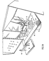
- FIG. 1 is a part perspective, part schematic illustration useful in explaining the method aspects and describing the apparatus.
- 10 refers to a support, which has an aperture 11 therein within which a mask 12 can be supported.
- the mask 12 includes apertures therein, aperture 13 representing a single aperture. These apertures may be circular holes, rectangular apertures, or the like. For example, a mask may have 600 holes of 0.1 mm diameter.
- the mask 12 has a main surface which is generally parallel to a major dimension of the support 10, i.e. for example both may have major dimensions or main surfaces, respectively, in a horizontal plane, when the mask is oriented as shown in Figure 1. While the apertures 13 may be of varying cross section, they all have axes which are normal to the plane of the mask 12.
- the plane of the mask is that plane within which the main surface of the mask lies.
- the aperture 11 and mask 12 are located so that a collimated polychromatic light beam 15 is directed perpendicular to the plane of the mask and parallel to the axes of each of the apertures.
- the light beam can, for example, be confined in a column defined by a cylindrical wall 14.
- defects or irregularities can readily be identified in the mask 12 by an observer, schematically depicted in Figure 1, viewing the mask 12 at an angle between 30 and 60° to the plane of the mask. Under'these circumstances, defects or irregularities will show up as a bright spot.
- the mask 12 may be rotated on the support 10 during the observation.
- the observation angle is preferably in the range of 30 to 45° to the plane of the mask 12. However, we have found that such rotation is not required especially if the mask can be translated in one or preferably two dimensions during the viewing step.
- auxiliary apparatus may be used to further enhance the inspection operation.
- auxiliary apparatus can include a modified microfilm reader.
- the microfilm reader has associated with it a viewing lens that can be positioned variably with respect to a viewing stage.
- the viewing stage of the microfilm reader is the support 10.
- the support 10 is moveable between two positions; in a first position the mask can be examined for the presence of a bright spot indicative of an irregularity, in the second position a portion of the mask area can be magnified by the modified microfilm reader.
- the operator In the first position, the operator can position the mask (in two dimensions) so as to locate any bright spots (indicative of defects or irregularities) relative to a fixed pointer assembly.
- the modified microfilm reader also includes a marker pen and a second pointer, fixed relative to each other and moveable with the support 10. The distance between the marker pen and second pointer is equal to the distance between the first pointer and the viewing lens.
- the operator positions the first pointer relative to any bright spot, he also operates the pen to record the relative position. Thereafter, to magnify the now located area of the mask, the viewing stage is moved relative to the viewing lens until the second pointer overlies the mark made by the pen. Because of the pre-established relation between the first pointer and viewing lens, and the pen and second pointer, when the second pointer overlies the mark made by the pen, the viewing lens overlies the area of the mask in which a potential defect or irregularity has been noted. The operator can then readily determine from the magnified image, whether or not the defect or irregularity is within the mask tolerances. For example a template can be used in a go/no go.measurement.
- a source of a cleaning fluid such as a compressed air tank 35 is associated with the microfilm reader.
- the operator can direct a jet of such cleaning fluid (compressed air for example) at the region on the mask in which the defect or irregularity is located. If the defect or irregularity is occasioned by debris which can be dislodged by the cleaning jet, the operator can readily effect this function.
- Figure 2A illustrates the columnar light beam conducting cylinder 14 associated with the support 10, on which is located a mask 12 including a plurality of apertures 13.
- the viewing lens 22 overlies that portion of the stage 10 corresponding to the mask's second position.
- the pointer assembly 19 includes the first pointer 30, and as is seen in Figure 2A, is fixed over the mask's first position.
- the mask's location relative to the pointer 30 is variable in that the mask 12 can be moved (in two dimensions, parallel to the plane of the mask 12).
- a pen 40 and a second pointer 41 are also attached to the stage 10 .
- a record sheet 42 i.e. any object which is fixed and on which the pen'40 can be used to make a visible mark.
- the distance between pen 40 and second pointer 41 is equal to the distance between the first pointer 30 and the viewing lens 22.
- the operator positions.a mask 12 in the stage 10, located in its "first position", that is generally underlying the pointer assembly 19.
- a polychromatic collimated light beam illuminates the mask 12.
- the source of this light beam is located within the cylinder 14. Any defects or irregularities, indicative of potential out-of-tolerance condition of any of the mask apertures, or debris adhering the mask, will be observed by the operator as a bright spot of light when the mask is viewed by the operator at the appropriate angle.
- the mask 12 When the operator notes one or more such bright spots, the mask 12 is positioned so that the fixed pointer 30 overlies a bright spot. At the same time, the pen 40 is depressed so as to make a mark on the record 42. Subsequently, the mask 12 is moved from its first position to its "second position", by translating the stage 10 under the viewing lens 22. Since the pen and second pointer 41 are fixed relative to the stage 10, this moves the pointer 41 in the general vicinity of the mark made by the pen 40 on the record 42. The stage 10 is then translated in two dimensions so as to bring the second pointer 41 into coincidence with the mark made by the pen 40 on the record 42. This ensures that the viewing lens 22 directly overlies the area on the mask 12 which had been associated with the bright spot when the mask was in its first position.
- the screen of the microfilm reader may have associated with it a template with indicia thereon indicating to the operator the desired mask characteristics, for example aperture size and spacing, etc.
- the first pointer 30 may actually comprise a hollow tube coupled to a source of a cleaning fluid such as the tank 35 shown in Figure 1.
- the operator can' then first flush the mask 30 with a jet of cleaning fluid in an attempt to dislodge any debris. This operation can be effected prior to projecting an image of the mask 12, or subsequent thereto. .
- Figure 2B represents the screen 51 of a microfilm reader.
- the reader magnifies an image of a portion of a mask 12 including apertures 13 therein.
- the image of the apertures 13 is represented in Figure 2B by the aperture images 44.
- a template with appropriate indicia can then be overlaid over screen 51 to allow the operator to readily determine the go/no go condition of any aperture.
- the reader para- f meters are arranged so that the entire screen 51 represents only a small fraction of the entire mask. The operator can readily pick out the irregularity in the image representing the mask irregularity.
- the invention provides a method and apparatus for readily detecting irregularities in an object with a plurality of apertures therethrough.
- the apparatus is relatively inexpensive, especially compared to prior art devices used to achieve the same purpose, and lifts the burden from the operator of optically reviewing the entire mask area. Instead, the absence of any bright spot on the mask 12 when illuminated by a polychromatic collimated light beam indicates the absence of any defects or irregularities and eliminates the necessity for the operator to optically review any portion of the mask 12. In the event that one or more bright spots are seen by the operator, he then need only optically view that portion of the mask associated with each of the bright spots.
- the use of the modified microfilm reader, and the apparatus used to position the viewing lens relative to the mask allows the operator to readily magnify selected portions of the mask for optical viewing.
- the viewing lens 22 is fixed and the mask is moved relative to the viewing lens to magnify and project selected areas of the mask 12. Conversely, it is also possible to fix the position of the mask and move the viewing lens 22 relative to the mask to magnify and project selected areas of the mask 12.
- the support for the mask 12 can be arranged so that it could be translated in two dimensions parallel to the plane of the mask, and also rotated in the same plane. Although as indicated above that rotation is not necessary, it should also be apparent that rotation can also be allowed.
Landscapes
- Physics & Mathematics (AREA)
- Health & Medical Sciences (AREA)
- Life Sciences & Earth Sciences (AREA)
- Chemical & Material Sciences (AREA)
- Analytical Chemistry (AREA)
- Biochemistry (AREA)
- General Health & Medical Sciences (AREA)
- General Physics & Mathematics (AREA)
- Immunology (AREA)
- Pathology (AREA)
- Investigating Materials By The Use Of Optical Means Adapted For Particular Applications (AREA)
- Length Measuring Devices By Optical Means (AREA)
Applications Claiming Priority (2)
| Application Number | Priority Date | Filing Date | Title |
|---|---|---|---|
| US334183 | 1981-12-24 | ||
| US06/334,183 US4447152A (en) | 1981-12-24 | 1981-12-24 | Method and apparatus for detecting defects in apertured plates |
Publications (2)
| Publication Number | Publication Date |
|---|---|
| EP0083053A2 true EP0083053A2 (fr) | 1983-07-06 |
| EP0083053A3 EP0083053A3 (fr) | 1984-01-11 |
Family
ID=23305984
Family Applications (1)
| Application Number | Title | Priority Date | Filing Date |
|---|---|---|---|
| EP82111808A Withdrawn EP0083053A3 (fr) | 1981-12-24 | 1982-12-20 | Procédé pour contrôler une pièce plate et percée ainsi que le dispositif pour sa mise en oeuvre |
Country Status (3)
| Country | Link |
|---|---|
| US (1) | US4447152A (fr) |
| EP (1) | EP0083053A3 (fr) |
| JP (1) | JPS58111706A (fr) |
Families Citing this family (4)
| Publication number | Priority date | Publication date | Assignee | Title |
|---|---|---|---|---|
| US4560273A (en) * | 1982-11-30 | 1985-12-24 | Fujitsu Limited | Method and apparatus for inspecting plated through holes in printed circuit boards |
| US4707132A (en) * | 1985-08-05 | 1987-11-17 | Dutton G Wayne | Process for sensing defects on a smooth cylindrical interior surface in tubing |
| US5773790A (en) * | 1997-01-21 | 1998-06-30 | General Electric Company | Beam blocking material and method for beam drilling and inspecting cooling holes |
| CN113945281B (zh) * | 2021-09-26 | 2025-03-21 | 福建省三棵树新材料有限公司 | 一种外墙真石漆雨痕的测试方法 |
Family Cites Families (7)
| Publication number | Priority date | Publication date | Assignee | Title |
|---|---|---|---|---|
| DE7014432U (de) * | Bergmann F Kg | Optisches Prüfgerät insbesondere für gedruckte Leiterbahnen bzw. gedruckte Verdrahtungen | ||
| US3680947A (en) * | 1970-04-21 | 1972-08-01 | Western Electric Co | Microscope apparatus with movable fluid bearing object support |
| JPS49105474A (fr) * | 1973-02-07 | 1974-10-05 | ||
| US4099881A (en) * | 1975-09-19 | 1978-07-11 | Transidyne General Corporation | Viewer for biological diffusion plate |
| JPS543587A (en) * | 1977-06-10 | 1979-01-11 | Hitachi Ltd | Inspecting apparatus |
| JPS54139784A (en) * | 1978-04-21 | 1979-10-30 | Ngk Insulators Ltd | Method and device for testing ceramic piece having innumerable through pores |
| JPS5614933A (en) * | 1979-07-18 | 1981-02-13 | Hitachi Ltd | Sample inspecting device |
-
1981
- 1981-12-24 US US06/334,183 patent/US4447152A/en not_active Expired - Lifetime
-
1982
- 1982-11-19 JP JP57202212A patent/JPS58111706A/ja active Granted
- 1982-12-20 EP EP82111808A patent/EP0083053A3/fr not_active Withdrawn
Also Published As
| Publication number | Publication date |
|---|---|
| JPH0125003B2 (fr) | 1989-05-16 |
| US4447152A (en) | 1984-05-08 |
| EP0083053A3 (fr) | 1984-01-11 |
| JPS58111706A (ja) | 1983-07-02 |
Similar Documents
| Publication | Publication Date | Title |
|---|---|---|
| DE69208413T2 (de) | Gerät zur automatischen Prüfung von Photomaske | |
| DE60036443T2 (de) | Verfahren und Vorrichtung zur Inspektion eines Retikels unter Verwendung von Luftbildern | |
| US5438413A (en) | Process for measuring overlay misregistration during semiconductor wafer fabrication | |
| EP0017371B1 (fr) | Appareil d'observation des défauts dans un dessin périodique | |
| KR200473035Y1 (ko) | 렌즈 검사 시스템 | |
| DE69534469T2 (de) | Verfahren und Vorrichtung zur automatisierten Prüfung von Photomasken | |
| US4347001A (en) | Automatic photomask inspection system and apparatus | |
| DE68908879T2 (de) | Verfahren und vorrichtung für optische messungen. | |
| US5204912A (en) | Defect verification and marking system for use with printed circuit boards | |
| US4555798A (en) | Automatic system and method for inspecting hole quality | |
| US4218142A (en) | Mask analysis | |
| JPH0318708A (ja) | 表面検査方法及び装置 | |
| JPH06105169B2 (ja) | 反復微細パターンの差異検出方法 | |
| US6023328A (en) | Photomask inspection method and apparatus | |
| US20070146870A1 (en) | Method for particle analysis and particle analysis system | |
| US20040240607A1 (en) | Method and system to inspect a component | |
| CA1191040A (fr) | Dispostif a reticule pour le controle de la qualite d'articles en cours de fabrication | |
| US4447152A (en) | Method and apparatus for detecting defects in apertured plates | |
| DE102019215972A1 (de) | Verfahren zur Messung einer Reflektivität eines Objekts für Messlicht sowie Metrologiesystem zur Durchführung des Verfahrens | |
| EP0040700B1 (fr) | Procédé et arrangement pour tester des systèmes optiques | |
| JPH05322783A (ja) | 基板観察装置 | |
| DE102024203890A1 (de) | Verfahren zur hochgenauen Lagebestimmung einer Struktur | |
| JP3415943B2 (ja) | 欠陥種別判定装置及びプロセス管理システム | |
| Sandland | Automatic inspection of mask defects | |
| GB2292603A (en) | Testing systems for counting contaminant particles |
Legal Events
| Date | Code | Title | Description |
|---|---|---|---|
| PUAI | Public reference made under article 153(3) epc to a published international application that has entered the european phase |
Free format text: ORIGINAL CODE: 0009012 |
|
| AK | Designated contracting states |
Designated state(s): DE FR GB |
|
| PUAL | Search report despatched |
Free format text: ORIGINAL CODE: 0009013 |
|
| 17P | Request for examination filed |
Effective date: 19831021 |
|
| AK | Designated contracting states |
Designated state(s): DE FR GB |
|
| STAA | Information on the status of an ep patent application or granted ep patent |
Free format text: STATUS: THE APPLICATION IS DEEMED TO BE WITHDRAWN |
|
| 18D | Application deemed to be withdrawn |
Effective date: 19841017 |
|
| RIN1 | Information on inventor provided before grant (corrected) |
Inventor name: OJALA, JON RAYMOND Inventor name: RAINFORD, ROBERT EDWARD Inventor name: MOSER, MARK MATTHEW |