EP0083061A2 - Automatische Spritzpistole für thermoplastisches Kunstharz - Google Patents
Automatische Spritzpistole für thermoplastisches Kunstharz Download PDFInfo
- Publication number
- EP0083061A2 EP0083061A2 EP82111860A EP82111860A EP0083061A2 EP 0083061 A2 EP0083061 A2 EP 0083061A2 EP 82111860 A EP82111860 A EP 82111860A EP 82111860 A EP82111860 A EP 82111860A EP 0083061 A2 EP0083061 A2 EP 0083061A2
- Authority
- EP
- European Patent Office
- Prior art keywords
- hot melt
- nozzle
- thermoplastic resin
- automatic gun
- gun
- Prior art date
- Legal status (The legal status is an assumption and is not a legal conclusion. Google has not performed a legal analysis and makes no representation as to the accuracy of the status listed.)
- Ceased
Links
Images



Classifications
-
- B—PERFORMING OPERATIONS; TRANSPORTING
- B05—SPRAYING OR ATOMISING IN GENERAL; APPLYING FLUENT MATERIALS TO SURFACES, IN GENERAL
- B05C—APPARATUS FOR APPLYING FLUENT MATERIALS TO SURFACES, IN GENERAL
- B05C11/00—Component parts, details or accessories not specifically provided for in groups B05C1/00 - B05C9/00
- B05C11/10—Storage, supply or control of liquid or other fluent material; Recovery of excess liquid or other fluent material
- B05C11/1042—Storage, supply or control of liquid or other fluent material; Recovery of excess liquid or other fluent material provided with means for heating or cooling the liquid or other fluent material in the supplying means upstream of the applying apparatus
-
- B—PERFORMING OPERATIONS; TRANSPORTING
- B05—SPRAYING OR ATOMISING IN GENERAL; APPLYING FLUENT MATERIALS TO SURFACES, IN GENERAL
- B05B—SPRAYING APPARATUS; ATOMISING APPARATUS; NOZZLES
- B05B13/00—Machines or plants for applying liquids or other fluent materials to surfaces of objects or other work by spraying, not covered by groups B05B1/00 - B05B11/00
- B05B13/02—Means for supporting work; Arrangement or mounting of spray heads; Adaptation or arrangement of means for feeding work
- B05B13/04—Means for supporting work; Arrangement or mounting of spray heads; Adaptation or arrangement of means for feeding work the spray heads being moved during spraying operation
- B05B13/0431—Means for supporting work; Arrangement or mounting of spray heads; Adaptation or arrangement of means for feeding work the spray heads being moved during spraying operation with spray heads moved by robots or articulated arms, e.g. for applying liquid or other fluent material to three-dimensional [3D] surfaces
Definitions
- the present invention relates to a connecting mechanism for a thermoplastic resin supply hose in an automatic gun for discharging thermoplastic resin.
- Hot melt is simply thermoplastic resin, and its materials include EVA-based, saturated polyester-based, polyamide-based, and polyolefin-based materials, other copolymers or their modified products, and rubber-based materials without vulcanization such as butyl rubber, polyisobutylene rubber, polybutene, SBR, etc.
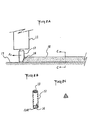
- Hot melt is emitted and spread on the surface of the material to be assembled by locating the hot-melt- emitting nozzle 2 close and almost perpendicular to said surface and by moving it in a certain direction Ai (or by moving the material to be assembled past the nozzle).
- the discharge hole of the nozzle is either in the shape of a circle 4 (in Figure 1C) or a slit 9 ( Figure 10).
- the material is discharged as strips, whose section is semicircular as shown in Figure 1B when the discharge hole is circular or flat 10 as shown in Figure 1E when the hole is slit-shaped.
- the nozzle When the discharge hole is circular, the nozzle can be moved in any direction.
- the hole is a slit, however, the nozzle is often moved in a line, since it is necessary to provide for perpendicular motion; that is; the slit is unidirectional. In other words, it is impossible to emit thermoplastic resin in all directions through a slit-type nozzle.
- the nozzle is preferred in which the nozzle hole faces one direction in the side wall of the nozzle to discharge and spread bands with a complex profile.
- the outline of such a nozzle is explained in the following.
- the nozzle is made in the shape of a tube with a bottom 12; a nozzle hole 14 is located in one of the side walls of this nozzle.
- the conditions under which hot-melt is discharged and spread through said nozzle are illustrated in Figure 2A.
- a hot melt band 18 is discharged and molded through said nozzle by moving said nozzle in a certain direction A 2 ; that is the required profile is discharged, applied, spread, and adhered to the surface of the material to be assembled 17.
- the nozzle must move in a direction A 2 opposite to the direction in which,the above-mentioned nozzle hole 14 points. Therefore, when the outline of a hot melt band to be emitted must be curved, the direction of nozzle movement must change along this curve part by part.
- a nozzle that is, a gun, which housed in a body with said nozzle, must be ultimately rotated by 360°, since most bands are of the profile type and endless.
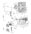
- FIG 3 illustrates the case in which the former hot-melt gun is installed on an industrial robot.
- the symbol 25 represents the gun body; 21 is the hot melt- emitting valve installed on said gun body; and 22 is the nozzle installed at the lower portion of said valve, which is of the tube type and has a nozzle hole 24 in one of its side walls (on the right side of the figure).
- a hot melt supply hose 28 is attached to the above gun body and is connected to a hot melt applicator 30.
- This hose must not only be heat-resistant and pressure-resistant, but must also be insulated, automatically temperature-controlled, and slightly flexible. That is to say, the hose is constructed of seven layers as shown in Figure 5.
- a Teflon tube 28E is connected to the above gun body.
- a stainless tube 28B is connected to the above gun body.
- insulation tape 28C is connected to the above gun body.
- band heater 28D is connected to the above gun body.
- thermoplastic resin (hot-melt) supply hose by providing a hollow spindle, which is supported and sealed with bearings and an 0-shaped seal in said automatic gun body, and which projects slightly from said automatic gun body, and by connecting said hollow spindle and the above thermoplastic resin (hot melt) supply hose by means of metal connector fittings in the connecting portion between the thermoplastic resin (hot melt) supply hose and the automatic gun body.
- the present invention is summarized by the concept of installing a hollow spindle, which is supported and sealed with bearings and an 0-shaped seal in an automatic gun body, and of connecting the projecting portion of said hollow spindle by means of metal fittings located at the end of a thermoplastic (hereafter referred to as hot melt) supply hose. Therefore, it is possible for hot melt supplied from the above hot-melt supply hose to pass through the above hollow spindle and always to reach the gun body even when the hollow spindle is rotating. That is to say, the automatic gun body can be freely rotated by freeing the nozzle, even when hot melt is being supplied. In other words, it is possible to change the discharge direction freely from the nozzle and easily to provide endless profile-type bands with any desired outline.
- a thermoplastic hereafter referred to as hot melt
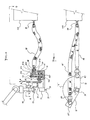
- An automatic gun body 45 provides air for operating an air valve, electricity for operating said air valve and an electromagnetic valve, etc., and supplies hot melt to a discharge valve 41, which is connected to the body.
- a hollow spindle 46 for supplying hot melt is first installed in the above automatic gun body 45, and said hollow spindle is supported in bearings 51.
- a bearing plate 50, a bearing washer 53, and a snap ring 52 are at- tached as accessory metal fittings for these bearings.
- An 0-shaped seal is attached to the lower portion of the bearings of the hollow spindle supported as described above.
- the necessary properties of the 0-shaped seal include heat resistance (above 300°C) and pressure resistance (about 100 kg/cm 2 ).
- the gap 47H between the outer diameter of the hollow spindle and the hole to hold the hollow spindle 47H is tightly sealed.
- the hollow portion 4611 of the bottom 46A of the hollow spindle is open and connected to the path 54 leading to the discharge valve 41.
- the upper portion of the above hollow spindle projects slightly beyond the automatic gun body, and a male screw thread 46S is cut in it. This male screw thread is connected to a metal connector fitting 57 located at the end of the hot melt supply hose 68.
- a rotary joint for air and a rotary contact for electricity can be installed whenever deemed necessary, since the above-mentioned flexible conduit 61 and air hose 62 have relatively great flexibility.
- FIG. 8 is a ground plan of Figure 6.
- Hot melt (including buld melt) is melted by a hot melt applicator 20 and moved through a hot melt supply hose 68 by means of a pressurized transfer pump.
- the hot melt flows through the metal connector fittings 57, 58, 59, located at the end of the above supply hose, through the hollow spindle 46 and into the path 54 leading to the discharge valve 41 of the automatic gun 45.
- the tip arm 64 of an industrial robot rotates around its axis (concentric to the axis of the nozzle 42 by a certain angle 0, the automatic gun body also rotates by the same angle S as shown in Figure 9.
- the above hollow spindle 46 also follows and rotates by the angle ⁇ .
- the hose will not restrict the motion, because there is enough looseness so that the hot melt supply hose 68 can follow easily. That is to say, it can easily rotate 360° around the nozzle.
- thermoplastic resin has been explained in the form of hot melt, but it is obvious that other general thermoplastic resins can also be used. Adhesive power is not always required for bands cf sealing materials, spacers, etc. The use and operational conditions for general thermoplastic resins are exactly the same as for the hot melt described above, and their explanation is omitted.
- a swivel connector type automatic gun of the present invention makes it possible to rotate the automatic gun freely around the nozzle while supplying molten thermoplastic resin to said automatic gun body and to discharge a thermoplastic resin band with a given profile and to spread said band in any outline onto the surface of the material to be treated.
- Figure 1A is a side view which explains the former discharge situation for hot melt.
- Figure 1B shows the cross section B-B of Figure 1A.
- Figure 1C is a front view of a circular nozzle (the base of the nozzle) for hot melt.
- Figure 1D is a front view (the bottom of a nozzle) of a slit-type nozzle for hot melt.
- Figure 1E is a cross section of a hand obtained by the use of a slit-type nozzle shown in Figure 1D to spread hot melt.
- Figure 2A is a side view which explains the action of the tube-type nozzle installed on the automatic gun of the present invention.
- Figure 2B shows an external view of said tube-type nozzle.
- Figure 2C shows section C-C of Figure 2A.
- Figure 3 is a side view of a former automatic gun installed at the tip arm of an industrial robot.
- Figure 4 is a ground plan to explain the action of the automatic gun shown in Figure 3.
- Figure 5 illustrates the design of the hot melt supply hose.
- Figure 6 is a side view sectional drawing of the connection between the automatic gun of the present invention and the hot-melt supply hose.
- Figure 7 is a detailed drawing of the "F" portion of Figure 6.
- Figure 8 is a ground plan of Figure 7.
- Figure 9 illustrates a drawing to explain the action in Figure 6 (and Figure 8).
- Figure 10 is a side-view sectional drawing of the use of an elbow type metal fitting for the hot melt supply hose.
- Figure 11 is a ground plan of the action of Figure 10.
- hollow spindle 47F... hole for the hollow spindle; 48C ... gap between the hollow spindle and the hole for the hollow spindle; 49, 79 ... 0-shaped seal; 51, 81 ... bearings; ,55 ... bearing cover; 56 ... bolt for installing the bearing cover; 57 ... metal connector fitting (connector screw); 58, 88 ... metal connector fitting (hose connection part); 59, 89 ... metal connector fitting (bag nut), and 87 ... elbow-type metal fitting.
Landscapes
- Engineering & Computer Science (AREA)
- Robotics (AREA)
- Coating Apparatus (AREA)
Applications Claiming Priority (2)
| Application Number | Priority Date | Filing Date | Title |
|---|---|---|---|
| JP215170/81 | 1981-12-29 | ||
| JP56215170A JPS58202074A (ja) | 1981-12-29 | 1981-12-29 | 熱可塑性樹脂吐出用自動ガン |
Publications (2)
| Publication Number | Publication Date |
|---|---|
| EP0083061A2 true EP0083061A2 (de) | 1983-07-06 |
| EP0083061A3 EP0083061A3 (de) | 1984-10-17 |
Family
ID=16667815
Family Applications (1)
| Application Number | Title | Priority Date | Filing Date |
|---|---|---|---|
| EP82111860A Ceased EP0083061A3 (de) | 1981-12-29 | 1982-12-21 | Automatische Spritzpistole für thermoplastisches Kunstharz |
Country Status (5)
| Country | Link |
|---|---|
| US (2) | US4592495A (de) |
| EP (1) | EP0083061A3 (de) |
| JP (1) | JPS58202074A (de) |
| AU (1) | AU553452B2 (de) |
| CA (1) | CA1232441A (de) |
Cited By (5)
| Publication number | Priority date | Publication date | Assignee | Title |
|---|---|---|---|---|
| FR2595965A1 (fr) * | 1986-03-24 | 1987-09-25 | Lerin Mecanicas | Applicateur d'adhesif thermofusible |
| WO1989010207A1 (fr) * | 1988-04-20 | 1989-11-02 | Lenhardt Maschinenbau Gmbh | Dispositif distributeur de substances pateuses a viscosite elevee, notamment pour l'application de materiaux d'etancheite et d'adhesifs sur des parties de la carrosserie pendant son montage |
| EP0524092A1 (de) * | 1991-07-17 | 1993-01-20 | Saint Gobain Vitrage International | Verfahren und Vorrichtung zum Herstellen eines Artikels mit einem Profilstrang |
| US5421940A (en) * | 1992-09-29 | 1995-06-06 | Saint Gobain Vitrage International | Process for the production of an automobile pane equipped with an elastomer frame of a predetermined shape |
| US5815997A (en) * | 1991-10-11 | 1998-10-06 | Saint Gobain Vitrage International | Glass pane with mounting frame |
Families Citing this family (27)
| Publication number | Priority date | Publication date | Assignee | Title |
|---|---|---|---|---|
| JPS61213109A (ja) * | 1985-03-18 | 1986-09-22 | Moon Star Co | 割金型の内面に離型剤をスプレ−するための装置 |
| US5000361A (en) * | 1987-08-24 | 1991-03-19 | Adco Products Inc. | Caulking gun nozzle |
| JPS6481294A (en) * | 1987-09-22 | 1989-03-27 | Juki Kk | Method and apparatus for forming thick-film circuit |
| US4901095A (en) * | 1988-11-10 | 1990-02-13 | Markem Corporation | Ink jet printing apparatus with adjustable print head |
| US5141165A (en) * | 1989-03-03 | 1992-08-25 | Nordson Corporation | Spray gun with five axis movement |
| US5102280A (en) | 1989-03-07 | 1992-04-07 | Ade Corporation | Robot prealigner |
| US4990201A (en) * | 1989-04-14 | 1991-02-05 | The Boeing Company | Method for reticulating perforated sheets |
| US5209406A (en) * | 1990-04-20 | 1993-05-11 | Ingersoll-Rand Company | Swivel valve for fluid jet cutting |
| US5316219A (en) * | 1992-07-08 | 1994-05-31 | Nordson Corporation | Coating apparatus with pattern width control |
| US5382395A (en) * | 1993-05-14 | 1995-01-17 | Admiral Equipment Co. | Profile extrusion apparatus and method for extruding a profile |
| USD354295S (en) | 1993-11-08 | 1995-01-10 | Nordson Corporation | Fluid dispensing module for dispensing heated fluids, such as hot melt adhesive |
| USD354296S (en) | 1993-11-08 | 1995-01-10 | Nordson Corporation | Fluid dispensing module for dispensing heated fluids, such as hot melt adhesive |
| US5538189A (en) * | 1994-03-04 | 1996-07-23 | Ransburg Corporation | Swivel fluid fitting |
| US5833147A (en) * | 1997-01-13 | 1998-11-10 | Abb Flexible Automation Inc. | Rotary union for robotic end effector |
| US5979794A (en) * | 1997-05-13 | 1999-11-09 | Ingersoll-Rand Company | Two-part stream dispensing for high viscosity materials |
| US5850976A (en) * | 1997-10-23 | 1998-12-22 | The Eastwood Company | Powder coating application gun and method for using the same |
| US6004124A (en) * | 1998-01-26 | 1999-12-21 | Stratasys, Inc. | Thin-wall tube liquifier |
| US6206963B1 (en) * | 1998-08-25 | 2001-03-27 | Philip Morris Incorporated | Nozzle |
| JP2002239435A (ja) * | 2001-02-16 | 2002-08-27 | Matsushita Electric Ind Co Ltd | 粘性材料塗布装置、及び粘性材料塗布方法 |
| US8534499B2 (en) * | 2005-10-21 | 2013-09-17 | Ch&I Technologies, Inc. | Integrated material transfer and dispensing system |
| EP1897625A1 (de) * | 2006-09-07 | 2008-03-12 | Sika Technology AG | Vorrichtung zur Abgabe von viskosem oder pastösem Material |
| CN105289924A (zh) * | 2014-07-14 | 2016-02-03 | 昆山捷凌电子科技有限公司 | 一种uv胶点胶照射检测一体机 |
| US10264720B1 (en) | 2015-06-23 | 2019-04-16 | Flextronics Ap, Llc | Lead trimming module |
| US9987650B2 (en) * | 2015-07-06 | 2018-06-05 | Integrated Packaging Solutions | Spray gun mount and retrofit kit |
| US11045929B1 (en) | 2016-04-26 | 2021-06-29 | Bright Machines, Inc. | Angle screw feeding module |
| US10220559B2 (en) | 2016-05-18 | 2019-03-05 | Axel Werner Van Briesen | Method and apparatus for making form-in-place gaskets |
| CN112090697B (zh) * | 2020-08-17 | 2021-11-26 | 陈英城 | 一种剪刀刀柄浸胶设备 |
Family Cites Families (21)
| Publication number | Priority date | Publication date | Assignee | Title |
|---|---|---|---|---|
| US1128798A (en) * | 1914-02-05 | 1915-02-16 | Milton P Mclaughlin | Flexible conduit. |
| US2270928A (en) * | 1940-01-18 | 1942-01-27 | American Brake Shoe & Foundry | Shaft seal |
| US2240458A (en) * | 1940-12-02 | 1941-04-29 | Gilbert & Barker Mfg Co | Dispensing hose and hose handling apparatus for mounting on dispensing pumps |
| US2384360A (en) * | 1942-02-09 | 1945-09-04 | All Flex Corp | Swivel pipe coupling |
| US2394715A (en) * | 1943-01-28 | 1946-02-12 | Chiksan Tool Company | Swivel coupling |
| US2379035A (en) * | 1943-06-30 | 1945-06-26 | Chiksan Tool Company | Swing joint |
| US2414997A (en) * | 1944-08-18 | 1947-01-28 | Earle R Atkins Company | Swivel joint assembly |
| FR937178A (fr) * | 1946-12-20 | 1948-08-10 | Dispositif pour la projection à chaud de bitumes, asphaltes, résines, cires et produits analogues | |
| US2518216A (en) * | 1948-03-18 | 1950-08-08 | Jaeger Machine Co | Swivel joint |
| US2587938A (en) * | 1948-05-11 | 1952-03-04 | Chiksan Co | Adjustable fluid handling conduit |
| US2879083A (en) * | 1953-11-16 | 1959-03-24 | Youngstown Sheet And Tube Co | High pressure swivel connector for adjustable conduits with strain relief means |
| US2817543A (en) * | 1954-04-16 | 1957-12-24 | Youngstown Sheet And Tube Co | Swivel connection having split bearing ring and means for retaining the same |
| US2812960A (en) * | 1954-05-21 | 1957-11-12 | Fawick Corp | Anti-corrosion rotary air-seal assembly |
| US3405959A (en) * | 1965-03-16 | 1968-10-15 | Filton Ltd | Fluid sealing means |
| US3303972A (en) * | 1965-10-23 | 1967-02-14 | Sels Peter J Van Loben | Dispenser mounting assembly |
| GB1178401A (en) * | 1966-01-25 | 1970-01-21 | Clarks Ltd | Improvements relating to the Application of Adhesives. |
| US3473832A (en) * | 1967-08-11 | 1969-10-21 | Inventex Gmbh | Ball-bearing swivel joint for fluid conduits |
| FR2419453A1 (fr) * | 1978-03-09 | 1979-10-05 | Pellenc & Motte | Dispositif d'accouplement de flexibles coaxiaux d'alimentation et de retour, aux machines et appareils hydrauliques |
| US4245759A (en) * | 1979-05-02 | 1981-01-20 | Nordson Corporation | Adhesive hand gun with swivel connector and safety mechanism |
| US4378959A (en) * | 1979-06-13 | 1983-04-05 | Thermwood Corporation | Apparatus for performing work functions |
| US4313624A (en) * | 1980-06-06 | 1982-02-02 | Zierden Company | Swivel cartridge |
-
1981
- 1981-12-29 JP JP56215170A patent/JPS58202074A/ja active Pending
-
1982
- 1982-12-16 US US06/450,260 patent/US4592495A/en not_active Expired - Fee Related
- 1982-12-21 EP EP82111860A patent/EP0083061A3/de not_active Ceased
- 1982-12-22 AU AU91784/82A patent/AU553452B2/en not_active Ceased
- 1982-12-22 CA CA000418345A patent/CA1232441A/en not_active Expired
-
1986
- 1986-03-06 US US06/818,816 patent/US4753824A/en not_active Expired - Fee Related
Cited By (6)
| Publication number | Priority date | Publication date | Assignee | Title |
|---|---|---|---|---|
| FR2595965A1 (fr) * | 1986-03-24 | 1987-09-25 | Lerin Mecanicas | Applicateur d'adhesif thermofusible |
| WO1989010207A1 (fr) * | 1988-04-20 | 1989-11-02 | Lenhardt Maschinenbau Gmbh | Dispositif distributeur de substances pateuses a viscosite elevee, notamment pour l'application de materiaux d'etancheite et d'adhesifs sur des parties de la carrosserie pendant son montage |
| EP0524092A1 (de) * | 1991-07-17 | 1993-01-20 | Saint Gobain Vitrage International | Verfahren und Vorrichtung zum Herstellen eines Artikels mit einem Profilstrang |
| US5336349A (en) * | 1991-07-17 | 1994-08-09 | Saint Gobain Vitrage International | Process and device for the production of an article equipped with a profiled bead |
| US5815997A (en) * | 1991-10-11 | 1998-10-06 | Saint Gobain Vitrage International | Glass pane with mounting frame |
| US5421940A (en) * | 1992-09-29 | 1995-06-06 | Saint Gobain Vitrage International | Process for the production of an automobile pane equipped with an elastomer frame of a predetermined shape |
Also Published As
| Publication number | Publication date |
|---|---|
| AU553452B2 (en) | 1986-07-17 |
| EP0083061A3 (de) | 1984-10-17 |
| JPS58202074A (ja) | 1983-11-25 |
| AU9178482A (en) | 1983-07-07 |
| US4592495A (en) | 1986-06-03 |
| CA1232441A (en) | 1988-02-09 |
| US4753824A (en) | 1988-06-28 |
Similar Documents
| Publication | Publication Date | Title |
|---|---|---|
| US4592495A (en) | Automatic gun for discharging thermoplastic resin | |
| CA1255893A (en) | Orbiting nozzle dispersion apparatus | |
| AU691255B2 (en) | Hydraulic ball style swivel fitting | |
| US10556304B2 (en) | Polymeric cover for robots | |
| US6499673B1 (en) | Pattern controllable dispensing apparatus | |
| US20060127584A1 (en) | Method and apparatus for applying flowable materials | |
| US20030010439A1 (en) | Seam sealing apparatus and process therefor | |
| US7487808B2 (en) | Coupling seal docking device comprising two of said coupling seals and container comprising at least one of said coupling seals | |
| CA2454320C (en) | Pipe coating apparatus and method | |
| KR850001395B1 (ko) | 산업용 로보트의 로보트 손목 | |
| CN105728263A (zh) | 一种涂胶嘴旋转的涂胶头 | |
| CN105772329A (zh) | 涂胶嘴旋转的涂胶头 | |
| EP0137581A1 (de) | Auftragepistole für thermoplastisches Material mit eingebautem Filter und Ventil zur Durchflussregelung | |
| JP2002527277A (ja) | 合成樹脂製遮断弁およびその製作方法 | |
| EP0203830B1 (de) | Dispergiervorrichtung mit umlaufender Düse | |
| JPH07259828A (ja) | ファスナ樹脂被覆装置及び方法 | |
| US4518016A (en) | Hot melt adhesive hose cuff | |
| US4945209A (en) | Welding gun swivel | |
| JPH0446829Y2 (de) | ||
| JPH01218658A (ja) | 2流体噴霧ノズルの回転スプレー装置 | |
| CA1253683A (en) | Nutating orifice dispersion apparatus | |
| KR100367125B1 (ko) | 패턴제어식분배장치 | |
| CN217473903U (zh) | 一种旋转喷涂机构 | |
| JPS6349329Y2 (de) | ||
| CN211412486U (zh) | 一种易清洁的包衣机喷枪管道 |
Legal Events
| Date | Code | Title | Description |
|---|---|---|---|
| PUAI | Public reference made under article 153(3) epc to a published international application that has entered the european phase |
Free format text: ORIGINAL CODE: 0009012 |
|
| AK | Designated contracting states |
Designated state(s): BE DE FR GB LU NL |
|
| PUAL | Search report despatched |
Free format text: ORIGINAL CODE: 0009013 |
|
| AK | Designated contracting states |
Designated state(s): BE DE FR GB LU NL |
|
| 17P | Request for examination filed |
Effective date: 19840822 |
|
| STAA | Information on the status of an ep patent application or granted ep patent |
Free format text: STATUS: THE APPLICATION HAS BEEN REFUSED |
|
| 18R | Application refused |
Effective date: 19870403 |
|
| RIN1 | Information on inventor provided before grant (corrected) |
Inventor name: ICHIKAWA, YOSHIO Inventor name: TODA, MASAAKI |