EP0083146A2 - Traktor mit abnehmbaren Ballastgewichten - Google Patents
Traktor mit abnehmbaren Ballastgewichten Download PDFInfo
- Publication number
- EP0083146A2 EP0083146A2 EP82304373A EP82304373A EP0083146A2 EP 0083146 A2 EP0083146 A2 EP 0083146A2 EP 82304373 A EP82304373 A EP 82304373A EP 82304373 A EP82304373 A EP 82304373A EP 0083146 A2 EP0083146 A2 EP 0083146A2
- Authority
- EP
- European Patent Office
- Prior art keywords
- weight
- vehicle according
- cylinder
- vehicle
- lowering
- Prior art date
- Legal status (The legal status is an assumption and is not a legal conclusion. Google has not performed a legal analysis and makes no representation as to the accuracy of the status listed.)
- Granted
Links
Images



Classifications
-
- B—PERFORMING OPERATIONS; TRANSPORTING
- B62—LAND VEHICLES FOR TRAVELLING OTHERWISE THAN ON RAILS
- B62D—MOTOR VEHICLES; TRAILERS
- B62D49/00—Tractors
- B62D49/08—Tractors having means for preventing overturning or tipping
- B62D49/085—Counterweight
-
- B—PERFORMING OPERATIONS; TRANSPORTING
- B62—LAND VEHICLES FOR TRAVELLING OTHERWISE THAN ON RAILS
- B62D—MOTOR VEHICLES; TRAILERS
- B62D49/00—Tractors
- B62D49/06—Tractors adapted for multi-purpose use
- B62D49/0621—Tractors adapted for multi-purpose use comprising traction increasing arrangements, e.g. all-wheel traction devices, multiple-axle traction arrangements, auxiliary traction increasing devices
- B62D49/0628—Tractors adapted for multi-purpose use comprising traction increasing arrangements, e.g. all-wheel traction devices, multiple-axle traction arrangements, auxiliary traction increasing devices using detachable weights
Definitions
- the present invention relates to a vehicle with detachable ballast weight and at least one lift cylinder for raising and lowering the weight.
- ballast weights It is well known to attach ballast weights to the front or rear of agricultural and earth-working vehicles and the weights are commonly detachable. Nevertheless attachment and removal are in many cases major operations; This is acceptable when the working conditions of a vehicle are well defined and subject to little variation. As against this there are some vehicles, e.g., agricultural tractors, which perform widely varying duties and which need ballast weight only part of the time.
- a vehicle (tractor) of the kind first mentioned above is known from DE 2 059208B which describes a partial solution to the foregoing problem.
- a special frame is mounted on a three point hitch. This frame can be raised beneath an attachment structure on the weight to engage and raise the weight. This makes it easy to handle the weight but introduces anotther disadvanatage in that the hitch is unusable whenever the ballast weight is employed. Moreover the weight projects undesirably in front of or behind the tractor.
- each additional weight is very heavy (typically 40kg).
- a base weight is fixed to the frame and additional weights are added or removed as required to achieve the correct ballasting. The weights have to be lifted on and off manually, which is not easy on account of their weight.
- the object of the present invention is to provide a vehicle, especially a tractor, with a compactly mounted ballast weight which can be raised and lowered non-manually over as short a lifting path as possible.
- the invention is characterised by means by which the weight is substantially vertically raisable and lowerable.
- These means are preferably two vertical guides, one on each side of the weight and the or each cylinder is preferably vertical, the weight being suspended from the cylinder(s).
- an important development of the invention is characterised by locking means engageable between the weight and guide means in at least one vertical position of the weight to fix the weight in position and allow detachment of the cylinder (s) for operation of an implement thereby.
- the vehicle according to the invention in another aspect is characterised by substantially vertical guide means for the weight, at least one substantially vertical lift cylinder having one end fixed and the other end detachably connected to.. the weight for the raising and lowering thereof, and a control valve arrangement for the lift cylinder (s) having a first position for raising the weight, a second position for lowering the weight, and a third position in which the cylinder(s) are connected as a hydraulic damping system.
- both the locking means and the control valve arrangement withthe third position are provided so that it is possible to achieve maximum flexibility of operation: running or lowering the weight and connection of an implement to the cylinders; running with the weight detached and connection of an implement to the cylinders and running with the weight acting as a damping means.
- the lifting apparatus comprises a guide frame which is arranged substantially vertically and which comprises two parallel channel-section uprights 12 and 13. The open faces of the uprights face each other.
- the uprights 12,13 are fixed, preferably by welding, to the side frame members 10 of the tractor chassis.
- the lifting means used in this arrangement are righthand and left-hand lifting cylinders 15 and 16, with piston rods 17 and 18 which each have a respective eye 19 and 20 at the end thereof, for mounting the coupling member 68 and 69 respectively of the weight 60 which is to be connected to the apparatus.
- each lifting cylinder 15 and 16 is connected to the respective upright 12 and 13 by way of a lug 14 and a pin or bolt 35 inserted through holes 21 in the flanges of the upright 12,13 and an eye in the lug 14.
- each coupling member 68,69 is a pin which is fixed to the ballast weight and is passed through the respective eye 19 or 20.
- the lifting cylinders 15 and 16 are connected to a hydraulic system 34 which provides both for controlled stepless vertical movement and also oscillation damping in respect of the vertical osciallating movement of the weights under the influence of pitching of the vehicle.
- the hydraulic system 34 (Fig.5) comprises a pressure accumulator 36, a 2/2 way valve 38, an adjustable throttle 4 0 , a 4/4 way valve 42, a pump 43 and a sump 44.
- the cylinders 15 and 16 are double acting and connected in parallel to "raise” and “lower” lines 45 and 46.
- Position 3 (the illustrated position) of the valve 42 isolates both lines 45 and 45 and enables the lifting apparatus to be locked in a fixed position the valve 38 remaining closed.
- Positions 4 and 1 of the 4/4 way valve 42 are selected for raising and lowering the piston rods 17 and 18, with the 2/2 way valve 38 closed.
- the throttle valve 40 permits adjustable damping of the weights, providing for optimum effect of the system, in particular adjustment of proper damping for various load conditions and terrains.
- the use of the hydraulic circuit both for producing the lifting movement and also for providing the damping weight system is achieved by the control circuit described.
- valves 38 and 42 can be operated in various ways but preferably with automatic control of the valve 38 (eg. by an electromagnet) so that it is in its position 1 for positions 1, 3, 4 of the valve 42 and in its position 2 for position 2 of the valve 42.
- the valve 42 is preferably a manual valve in the tractor can or on the side of the vehicle, enabling the weight or implement being lifted to be observed while operating the valve.
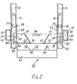
- the ballast weight 60 comprises a support frame 61 which comprises two side members 62 and 63 which are disposed parallel to each other and which are connected by an end plate 67. At their respective outward longitudinal sides, the side members 62 and 63 have upstanding side plates 64 and 65 respectively. The space between the frame members 62 and 63 forms a downwardly tapering trapezium, ie. a dovetail slot. All components of the support frame 61 may be welded together.
- Figs. 2 to 4 show an embodiment wherein there are only two guide rollers secured to each of the sideplates 64 and 65.
- Each pair of guide rollers eg. rollers 71 and 72 in Fig, 1) straddles the corresponding upright 12 or 13 and guides the weight 60 for vertical movement.
- guide rail members instead of guide rollers.
- the guide rollers 71 to 75 bear against the flanges of the uprights 12 and 13 of the guide frame, and slide along the uprights 12 and 13 when the ballast weight is moved or slid vertically.
- front and rear stub bars 80 are secured to the sideplate 64 and front and. rear stub bars 81 are secured to the sideplate 65 of the support frame 61, for rigidly connecting the ballast weight 60 to the guide frame formed by the uprights 12 and 13.
- the bars 80 and 81 have bores 82 and 83 and the flanges of the uprights 12 and 13 have a plurality of bores 84 and 85 disposed one above the other.
- Additional weights 93 can be inserted into the support frame 61 of the ballast weight 60.
- Each additional weight 93 is of a flattended Z-shaped corss-section in side view and has two V-shaped recesses 96 and 97 which form the top part of the weight into a dovetail tongue 98 (Fig.2) which can be slid into the aforementioned dovetail slot in the frame 61. Accordingly each additional weight 93 is positively fixed with respect to the support frame 61.
- the additional weights rest in each other by virtue of their cross-section (see Fig. 4) thereby approximating to a unitary mass. Additional interengagement is proveded by front projections 94 which engage in rear recesses 95.
- a towing clevis 79 can be mounted on the front of a yoke 76.
- the yoke 76 completes the fourth side of the support frame 61 of the weight and performs several functions.
- the yoke has side arms with bores 76 and the yoke is pinned to the side plates 64 and 65 of the support frame 61 by means of pins or bolts 78.
- the holes 77 can be selected in accordance with the number of weights so that the front bar of the yoke is close against the front weight 93.
- the weights are thereby locked in place, especially extra front weights (see Fig.3) which are supported solely by the projection 94 and recesses 95.
- the front bar of the yoke 76 carries the clevis 79 and ensures that this always has a mounting of adequate strength for the draught loads which it has to handle.
- the hydraulic system 34 is switched to the damping mode and the ballast weight 60 which is coupled to the cylinders 15 and 16 is utilised as a damping weight.
- the oscillating movement of the ballast weight on the vehicle in a vertical direction under the influence of pitching of the vehicle during transportation thereof is thus damped.
- Fig. 6 shows how the arrangement can be converted to act as implement lift, eg. for a front-end mounted implement.
- the weight 60 is fixed to the frame uprights 12 and 13 as described above and the coupling pins 68,69 have been removed to uncouple the cylinders 15, 16 from the weights.
- the cylinders now act as lift cylinders for two lower links 22 connected by a cross bar 23.
- the rear ends of the links 22 are connected to the piston rod eyes 19, 20 by pivot pins 24.
- the links are pivotally mounted, somewhat forward of their rear ends, in forked brackets 25 fixed to the outer faces of the uprights 12, 13. Pivot pins 26 pass throught the forked brackets and the links.
- the brackets 25 may be permanently attached and the links 22 be attached and removed by means of the pins 24 and 26. Alternatively the brackets may also be removable, being fixed by bolts (not shown).
- valve 42 When the valve 42 is set to position 1 to lower the piston rods 17, 18 it is apparent that an implement mounted at the front of the lower links 22 will be raised. In position 4 which raises the piston rods the implement will be lowered.
- an upper link (not shown) may be pivoted to a clevis 28 on a cross-bar 29 spanning the side-plates 64 , 65, of the weight support frame 61.
- the bar 29 may be detachable or a permanent, welded part of the frame 61
- the preferred cylinder arrangement is as shown with the closed end at the top fixed to the rame uprights 12,13 it is possible to invert the cylinders and fix the rod ends and attach the closed ends by way of the eyes 14 to the weight 60 or links 22.
- the cylinders 15, 16 it is also possible to anchor the lower ends and connect the top ends to the weight or links via direction-reversing cables or chains passing over pulleys or sprockets at the top of the uprights 12,13.
Landscapes
- Engineering & Computer Science (AREA)
- Chemical & Material Sciences (AREA)
- Combustion & Propulsion (AREA)
- Transportation (AREA)
- Mechanical Engineering (AREA)
- Body Structure For Vehicles (AREA)
- Machines For Laying And Maintaining Railways (AREA)
- Harvester Elements (AREA)
Priority Applications (2)
| Application Number | Priority Date | Filing Date | Title |
|---|---|---|---|
| AT82304373T ATE27125T1 (de) | 1981-12-29 | 1982-08-19 | Traktor mit abnehmbaren ballastgewichten. |
| ES515702A ES515702A0 (es) | 1981-12-29 | 1982-09-14 | "un vehiculo especialmente un tractor, con un peso de lastre desmontable y al menos un cilindro de elevacion". |
Applications Claiming Priority (2)
| Application Number | Priority Date | Filing Date | Title |
|---|---|---|---|
| EP81110815 | 1981-12-29 | ||
| EP81110815 | 1981-12-29 |
Publications (3)
| Publication Number | Publication Date |
|---|---|
| EP0083146A2 true EP0083146A2 (de) | 1983-07-06 |
| EP0083146A3 EP0083146A3 (en) | 1985-10-02 |
| EP0083146B1 EP0083146B1 (de) | 1987-05-13 |
Family
ID=8188094
Family Applications (1)
| Application Number | Title | Priority Date | Filing Date |
|---|---|---|---|
| EP82304373A Expired EP0083146B1 (de) | 1981-12-29 | 1982-08-19 | Traktor mit abnehmbaren Ballastgewichten |
Country Status (7)
| Country | Link |
|---|---|
| US (1) | US4518305A (de) |
| EP (1) | EP0083146B1 (de) |
| AU (1) | AU551380B2 (de) |
| CA (1) | CA1197881A (de) |
| DE (2) | DE3276304D1 (de) |
| MX (1) | MX158437A (de) |
| ZA (1) | ZA826694B (de) |
Cited By (6)
| Publication number | Priority date | Publication date | Assignee | Title |
|---|---|---|---|---|
| EP0087203A3 (de) * | 1982-02-19 | 1985-05-02 | C. van der Lely N.V. | Leichtgewichttraktor mit abnehmbarem Kupplungs- und Ballastgerät |
| DE3442557A1 (de) * | 1984-11-22 | 1986-05-28 | Deere & Co., Moline, Ill., US, Niederlassung Deere & Co. European Office, 6800 Mannheim | Anschluss- und kupplungsvorrichtung zum frontseitigen anbau an ein arbeitsfahrzeug |
| ES2207416A1 (es) * | 2002-11-14 | 2004-05-16 | Francisco Saiz Rios | Sistema estabilizador para tractores. |
| EP2275324A1 (de) * | 2009-07-17 | 2011-01-19 | Althimasse | Ausgleichsgewichtssystem für einen Traktor, insbesondere einen landwirtschftlichen Traktor. |
| US20190002041A1 (en) * | 2017-06-30 | 2019-01-03 | Althimasse | Support device for tractor, in particular of agricultural type |
| CN112942456A (zh) * | 2021-01-29 | 2021-06-11 | 上海三一重机股份有限公司 | 一种装载机动臂减震系统和作业机械 |
Families Citing this family (16)
| Publication number | Priority date | Publication date | Assignee | Title |
|---|---|---|---|---|
| JPH0612062Y2 (ja) * | 1989-06-19 | 1994-03-30 | 新キャタピラー三菱株式会社 | カウンタウエイト着脱装置 |
| US5598935A (en) * | 1993-03-18 | 1997-02-04 | American Crane Corporation | Frame structure for lift crane machinery |
| US5601145A (en) * | 1995-03-22 | 1997-02-11 | Thompson; L. D. | Farm implement hillside leveling device |
| CA2252446C (en) * | 1997-10-31 | 2003-06-10 | Grove U.S. L.L.C. | Automatic leveling and synchronization system for counterweight removal and installation |
| US6533319B1 (en) * | 1998-12-23 | 2003-03-18 | Deere & Company | Ballast attachment for tractor three-point hitch |
| GB2352704B (en) * | 1999-08-04 | 2004-02-11 | Agco Gmbh & Co | Ballast weight arrangement |
| US6880854B2 (en) * | 2002-05-30 | 2005-04-19 | Deere & Company | Stabilizing weight assemblies for tractors |
| US20040140109A1 (en) * | 2003-01-16 | 2004-07-22 | Deere & Company, A Delaware Corporation | Three-point hitch having flotation |
| US20120153605A1 (en) * | 2010-12-20 | 2012-06-21 | Caterpillar Inc. | Counterweight system |
| RU2469523C1 (ru) * | 2011-04-26 | 2012-12-20 | Федеральное государственное образовательное учреждение высшего профессионального образования "Воронежский государственный аграрный университет имени К.Д. Глинки" (ФГОУ ВПО ВГАУ) | Устройство для регулирования положения балластного груза на полураме трактора |
| JP6066808B2 (ja) * | 2013-04-10 | 2017-01-25 | 株式会社クボタ | 作業車 |
| US10293874B2 (en) | 2016-04-26 | 2019-05-21 | Agco Corporation | Self mounting ballast weight system |
| DE102016005505A1 (de) * | 2016-05-04 | 2017-11-09 | Liebherr-Werk Ehingen Gmbh | Mobilkran mit Ballastaufnahme sowie Verfahren zur Ballastierung eines Mobilkrans |
| RU178614U1 (ru) * | 2017-09-12 | 2018-04-13 | Федеральное государственное бюджетное образовательное учреждение высшего образования "Санкт-Петербургский государственный архитектурно-строительный университет" | Устройство для предотвращения опрокидывания транспортного средства |
| US11027787B2 (en) | 2017-10-31 | 2021-06-08 | Deere & Company | Attachment assembly for use with a work machine |
| US11858564B2 (en) | 2021-08-17 | 2024-01-02 | Cnh Industrial America Llc | Vehicle with repositionable ballast |
Family Cites Families (10)
| Publication number | Priority date | Publication date | Assignee | Title |
|---|---|---|---|---|
| US2891681A (en) * | 1956-12-05 | 1959-06-23 | Caterpillar Tractor Co | Rotatable counterweight mechanism |
| DE2225891C2 (de) * | 1972-05-27 | 1984-04-05 | Klöckner-Humboldt-Deutz AG, 5000 Köln | Vorrichtung zum Anschluß eines Ballastgewichtes an einen Schlepper |
| DE2228049A1 (de) * | 1972-06-09 | 1973-12-20 | Kloeckner Humboldt Deutz Ag | Geraeteanbauvorrichtung fuer fahrzeuge mit ausgleichsballast |
| US3902735A (en) * | 1974-06-03 | 1975-09-02 | Caterpillar Tractor Co | Hydraulic counterweight removal mechanism |
| US3953040A (en) * | 1975-03-05 | 1976-04-27 | Caterpillar Tractor Co. | Leveling and lockup system for wheel tractor suspension system |
| US4133552A (en) * | 1977-06-15 | 1979-01-09 | Gerald Sheine | Control means for a vehicular tractor-trailer connection |
| US4232883A (en) * | 1979-03-19 | 1980-11-11 | Ford Motor Company | Counterweight assembly for a vehicle |
| US4344733A (en) * | 1979-09-17 | 1982-08-17 | J. I. Case Company | Hydraulic control circuit for decelerating a swinging backhoe |
| US4363412A (en) * | 1980-08-14 | 1982-12-14 | Kidde, Inc. | Crane counterweight and handling method |
| DE3177077D1 (en) * | 1981-04-22 | 1989-08-17 | Deere & Co | Front implement hitch device for a front covered vehicle for use in agriculture and/or the building industry, in particular for a farming tractor |
-
1982
- 1982-08-19 EP EP82304373A patent/EP0083146B1/de not_active Expired
- 1982-08-19 DE DE8282304373T patent/DE3276304D1/de not_active Expired
- 1982-08-19 DE DE198282304373T patent/DE83146T1/de active Pending
- 1982-09-13 ZA ZA826694A patent/ZA826694B/xx unknown
- 1982-12-06 US US06/446,934 patent/US4518305A/en not_active Expired - Fee Related
- 1982-12-14 MX MX195646A patent/MX158437A/es unknown
- 1982-12-16 CA CA000417937A patent/CA1197881A/en not_active Expired
- 1982-12-16 AU AU91584/82A patent/AU551380B2/en not_active Ceased
Cited By (9)
| Publication number | Priority date | Publication date | Assignee | Title |
|---|---|---|---|---|
| EP0087203A3 (de) * | 1982-02-19 | 1985-05-02 | C. van der Lely N.V. | Leichtgewichttraktor mit abnehmbarem Kupplungs- und Ballastgerät |
| DE3442557A1 (de) * | 1984-11-22 | 1986-05-28 | Deere & Co., Moline, Ill., US, Niederlassung Deere & Co. European Office, 6800 Mannheim | Anschluss- und kupplungsvorrichtung zum frontseitigen anbau an ein arbeitsfahrzeug |
| ES2207416A1 (es) * | 2002-11-14 | 2004-05-16 | Francisco Saiz Rios | Sistema estabilizador para tractores. |
| WO2004043771A1 (es) * | 2002-11-14 | 2004-05-27 | Francisco Saiz Rios | Sistema estabilizador para tractores |
| EP2275324A1 (de) * | 2009-07-17 | 2011-01-19 | Althimasse | Ausgleichsgewichtssystem für einen Traktor, insbesondere einen landwirtschftlichen Traktor. |
| FR2948088A1 (fr) * | 2009-07-17 | 2011-01-21 | Lory Fonderies | Systeme de contrepoids pour tracteur, notamment de type agricole |
| US20190002041A1 (en) * | 2017-06-30 | 2019-01-03 | Althimasse | Support device for tractor, in particular of agricultural type |
| US10933928B2 (en) * | 2017-06-30 | 2021-03-02 | Althimasse | Support device for tractor, in particular of agricultural type |
| CN112942456A (zh) * | 2021-01-29 | 2021-06-11 | 上海三一重机股份有限公司 | 一种装载机动臂减震系统和作业机械 |
Also Published As
| Publication number | Publication date |
|---|---|
| EP0083146A3 (en) | 1985-10-02 |
| AU551380B2 (en) | 1986-04-24 |
| CA1197881A (en) | 1985-12-10 |
| ZA826694B (en) | 1984-04-25 |
| US4518305A (en) | 1985-05-21 |
| DE3276304D1 (en) | 1987-06-19 |
| MX158437A (es) | 1989-01-30 |
| AU9158482A (en) | 1983-07-07 |
| EP0083146B1 (de) | 1987-05-13 |
| DE83146T1 (de) | 1983-12-08 |
Similar Documents
| Publication | Publication Date | Title |
|---|---|---|
| EP0083146A2 (de) | Traktor mit abnehmbaren Ballastgewichten | |
| US4127951A (en) | Automatic coupling mechanism for snow-plows and the like | |
| US4034873A (en) | Wheel supporting towing sling attachment | |
| US6238004B1 (en) | Attachment mounting structure | |
| US5639106A (en) | Tractor-trailer fifth wheel air suspension assembly | |
| US4475761A (en) | Vehicle having pivotable wall parts | |
| US3031208A (en) | Universal tractor hitch | |
| CA2155242C (en) | Towing arrangement | |
| US2519974A (en) | Tractor-implement supporting cradle | |
| US4815915A (en) | Under-vehicle towing apparatus | |
| CA1286339C (en) | Retroffitable vehicle framework means and method for interchangeable usewith a variety of attachment units | |
| US3412489A (en) | Coupling apparatus | |
| US20200170171A1 (en) | Tractor system and method | |
| US3908842A (en) | Tow truck | |
| US5404958A (en) | Lifting structure for an agricultural tractor | |
| US6035941A (en) | Tractor with a front loader | |
| US2782944A (en) | Vehicle towing device | |
| EP0138519A2 (de) | Zugvorrichtungen | |
| US5394948A (en) | Hitch assembly for a tractor | |
| JPS6014819Y2 (ja) | イコライザ−バ−サポ−ト組立体 | |
| US5988664A (en) | Apparatus for towing a disabled truck tractor | |
| US2081939A (en) | Implement hoisting frame for tractors | |
| CA1199611A (en) | Towing lift | |
| GB2380720A (en) | Vehicle hitch | |
| US3940000A (en) | Universal hydraulic lift attachment for tractors |
Legal Events
| Date | Code | Title | Description |
|---|---|---|---|
| PUAI | Public reference made under article 153(3) epc to a published international application that has entered the european phase |
Free format text: ORIGINAL CODE: 0009012 |
|
| AK | Designated contracting states |
Designated state(s): AT DE FR GB IT SE |
|
| ITCL | It: translation for ep claims filed |
Representative=s name: LENZI & C. |
|
| EL | Fr: translation of claims filed | ||
| TCAT | At: translation of patent claims filed | ||
| DET | De: translation of patent claims | ||
| PUAL | Search report despatched |
Free format text: ORIGINAL CODE: 0009013 |
|
| AK | Designated contracting states |
Designated state(s): AT DE FR GB IT SE |
|
| 17P | Request for examination filed |
Effective date: 19851019 |
|
| 17Q | First examination report despatched |
Effective date: 19860410 |
|
| ITF | It: translation for a ep patent filed | ||
| GRAA | (expected) grant |
Free format text: ORIGINAL CODE: 0009210 |
|
| AK | Designated contracting states |
Kind code of ref document: B1 Designated state(s): AT DE FR GB IT SE |
|
| REF | Corresponds to: |
Ref document number: 27125 Country of ref document: AT Date of ref document: 19870515 Kind code of ref document: T |
|
| REF | Corresponds to: |
Ref document number: 3276304 Country of ref document: DE Date of ref document: 19870619 |
|
| ET | Fr: translation filed | ||
| PLBE | No opposition filed within time limit |
Free format text: ORIGINAL CODE: 0009261 |
|
| STAA | Information on the status of an ep patent application or granted ep patent |
Free format text: STATUS: NO OPPOSITION FILED WITHIN TIME LIMIT |
|
| 26N | No opposition filed | ||
| PGFP | Annual fee paid to national office [announced via postgrant information from national office to epo] |
Ref country code: AT Payment date: 19930818 Year of fee payment: 12 |
|
| PGFP | Annual fee paid to national office [announced via postgrant information from national office to epo] |
Ref country code: SE Payment date: 19930825 Year of fee payment: 12 |
|
| ITTA | It: last paid annual fee | ||
| PG25 | Lapsed in a contracting state [announced via postgrant information from national office to epo] |
Ref country code: AT Effective date: 19940819 |
|
| PG25 | Lapsed in a contracting state [announced via postgrant information from national office to epo] |
Ref country code: SE Effective date: 19940820 |
|
| EAL | Se: european patent in force in sweden |
Ref document number: 82304373.2 |
|
| EUG | Se: european patent has lapsed |
Ref document number: 82304373.2 |
|
| PGFP | Annual fee paid to national office [announced via postgrant information from national office to epo] |
Ref country code: FR Payment date: 19970818 Year of fee payment: 16 |
|
| PGFP | Annual fee paid to national office [announced via postgrant information from national office to epo] |
Ref country code: DE Payment date: 19971022 Year of fee payment: 16 |
|
| PGFP | Annual fee paid to national office [announced via postgrant information from national office to epo] |
Ref country code: GB Payment date: 19980724 Year of fee payment: 17 |
|
| PG25 | Lapsed in a contracting state [announced via postgrant information from national office to epo] |
Ref country code: FR Free format text: LAPSE BECAUSE OF NON-PAYMENT OF DUE FEES Effective date: 19990430 |
|
| PG25 | Lapsed in a contracting state [announced via postgrant information from national office to epo] |
Ref country code: DE Free format text: LAPSE BECAUSE OF NON-PAYMENT OF DUE FEES Effective date: 19990601 |
|
| REG | Reference to a national code |
Ref country code: FR Ref legal event code: ST |
|
| PG25 | Lapsed in a contracting state [announced via postgrant information from national office to epo] |
Ref country code: GB Free format text: LAPSE BECAUSE OF NON-PAYMENT OF DUE FEES Effective date: 19990819 |
|
| GBPC | Gb: european patent ceased through non-payment of renewal fee |
Effective date: 19990819 |