EP2275324A1 - Ausgleichsgewichtssystem für einen Traktor, insbesondere einen landwirtschftlichen Traktor. - Google Patents
Ausgleichsgewichtssystem für einen Traktor, insbesondere einen landwirtschftlichen Traktor. Download PDFInfo
- Publication number
- EP2275324A1 EP2275324A1 EP10165525A EP10165525A EP2275324A1 EP 2275324 A1 EP2275324 A1 EP 2275324A1 EP 10165525 A EP10165525 A EP 10165525A EP 10165525 A EP10165525 A EP 10165525A EP 2275324 A1 EP2275324 A1 EP 2275324A1
- Authority
- EP
- European Patent Office
- Prior art keywords
- mass
- main
- tractor
- main mass
- transverse
- Prior art date
- Legal status (The legal status is an assumption and is not a legal conclusion. Google has not performed a legal analysis and makes no representation as to the accuracy of the status listed.)
- Granted
Links
- 230000011664 signaling Effects 0.000 claims description 6
- 238000005303 weighing Methods 0.000 claims description 3
- 238000004873 anchoring Methods 0.000 claims description 2
- 229910001018 Cast iron Inorganic materials 0.000 description 2
- 241000931526 Acer campestre Species 0.000 description 1
- 239000006185 dispersion Substances 0.000 description 1
- 230000010354 integration Effects 0.000 description 1
- 230000014759 maintenance of location Effects 0.000 description 1
- 238000004519 manufacturing process Methods 0.000 description 1
- 238000000465 moulding Methods 0.000 description 1
- 230000000149 penetrating effect Effects 0.000 description 1
- BASFCYQUMIYNBI-UHFFFAOYSA-N platinum Chemical compound [Pt] BASFCYQUMIYNBI-UHFFFAOYSA-N 0.000 description 1
- 239000007787 solid Substances 0.000 description 1
- 230000000007 visual effect Effects 0.000 description 1
Images


Classifications
-
- B—PERFORMING OPERATIONS; TRANSPORTING
- B62—LAND VEHICLES FOR TRAVELLING OTHERWISE THAN ON RAILS
- B62D—MOTOR VEHICLES; TRAILERS
- B62D49/00—Tractors
- B62D49/06—Tractors adapted for multi-purpose use
- B62D49/0621—Tractors adapted for multi-purpose use comprising traction increasing arrangements, e.g. all-wheel traction devices, multiple-axle traction arrangements, auxiliary traction increasing devices
- B62D49/0628—Tractors adapted for multi-purpose use comprising traction increasing arrangements, e.g. all-wheel traction devices, multiple-axle traction arrangements, auxiliary traction increasing devices using detachable weights
Definitions
- the invention relates to the field of weighting masses intended to be attached to a lifting system of a tractor, particularly of agricultural type.
- this system has the disadvantage of significantly increasing the front or rear overhang of the tractor when the secondary mass is mounted, which does not facilitate the maneuvering of the tractor and may cause difficulties in balancing the vehicle.
- the object of the present invention is to overcome the above drawbacks of known counterweight systems, by proposing a system for loading an adjustable mass on the lifting system of the tractor consisting of one or two blocks, in front or the rear, while reducing as much as possible the overhang front or rear, regardless of the weight on board.
- the subject of the invention is a main weighting mass intended to be attached to a lifting system of a tractor, particularly of agricultural type, by means of two axes transverse to the direction of progression of the tractor, arranged in alignment with each other and protruding from the side faces of the mass, the main mass comprising means for adjusting the vertical position of the transverse axes, adapted to modify the ground clearance of the main mass of weight when attached to the lift system.
- the main mass can occupy several vertical positions, which allows to stack vertically several blocks, including the main mass and one or more secondary masses located below the main mass.
- the front overhang is not or very slightly increased compared to the "main mass only" configuration.
- the masses as the masses are superimposed, they offer a frontal surface that can be drawn with continuity between the different parts (no breakage), which contributes to a perfect integration of the masses between them and forms a system of counterweight to the aesthetic appearance.
- each of the transverse axes is mounted rigidly and perpendicularly to a fixing plate adapted to be fixed to the body of the main mass at a position chosen from a plurality of predetermined rotational positions about an axis of adjustment substantially parallel to the transverse axis, said transverse axis and adjustment axis being eccentric relative to each other.
- the fixing plate is fixed to the body of the main mass by fixing screws arranged to form the four vertices of a quadrilateral, in particular a square, the plate being thus able to be fixed to the body of the mass in four distinct positions differentiable by rotation of the plate around the axis of adjustment.
- the adjustment axis is constituted by a shoulder centered on the intersection of the lines, for example diagonals, passing through the fixing screws, said shoulder being mounted rigidly on the plate. , opposite the transverse axis, and being introduced into a corresponding bore formed in the body of the main mass.
- the main mass comprises an upper retaining device formed of two plates substantially parallel to the direction of progression of the tractor, between which an upper retaining pin can be mounted, and connected to a third means of retaining / lifting the tractor.
- the upper retaining device comprises a fastening means for a winching and / or a means for supporting a visibility flag.
- the main mass comprises a fastening means for winching and / or means for supporting a visibility flag located on a front face of the mass.
- the main mass comprises in its lower part at least one housing for receiving a secondary mass of weighting, able to be disposed below the main mass, the housing being opening on a front face of the main mass, with respect to the direction of progression of the tractor.
- the secondary mass can be loaded and hooked by the main mass without even the driver down from his driving position.
- the secondary mass is hooked by simple advance of the tractor towards the secondary mass placed on the ground, while the main mass is presented at a height suitable for the attachment of the two masses together.
- the main mass comprises two receiving housings cooperating with corresponding protuberances of the secondary mass, and ensuring therewith an anchorage by a connection of the "dovetail” type, of which the longitudinal direction is substantially parallel to the direction of progression of the tractor.
- each housing comprises a rear zone whose transverse dimensions are narrower than in the front zone, so as to form a wedge during the introduction of the secondary mass into the main mass. by the front of the latter.
- the main mass comprises at least one lighting light on its front face, with respect to the direction of progression of the tractor, said lamp being at least partially embedded in the body of the mass.
- the upper retaining device supports at least one lighting and / or signaling light, in particular via a ramp transverse to the direction of progression of the tractor, on which said mounting is mounted. less a lighting and / or signaling device.
- the subject of the invention is also a secondary mass of weighting adapted to be fixed below a main mass having all or some of the preceding characteristics.
- the secondary mass comprises protuberances cooperating with said at least one receiving housing of the main mass.
- the secondary mass referred to in this case as the first secondary mass, comprises at least one receiving housing of another secondary mass, intended to be fixed below the first secondary mass.
- the invention also relates to a counterweight system for a tractor, in particular of agricultural type, comprising a main weighing mass and at least one secondary mass of weighting having the characteristics indicated above.
- FIG. 1 a main mass 1 of a counterweight system according to the invention intended to be mounted on a tractor, for example of agricultural type (not shown). This mass is designated “main mass” to the extent that it is possible to add optional, a secondary mass as will be described later.
- the main mass 1 forms a one-piece assembly intended to be hooked to a lifting system (not shown) front or rear of the tractor, conventionally consisting of two arms provided at their free end with a "U" hook forming a bearing to receive transverse axes 2, 3 protruding from the sides of the main mass 1.
- the connection between the transverse axes 2, 3 and the arms is achieved via ball joints and locking means (not shown) adapted to trap the pins 2, 3 and their respective ball joint in the U.
- the transverse axes 2, 3 are so called in relation to the direction of progression of the tractor.
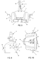
- Each of the transverse axes is mounted rigidly and perpendicularly on a mounting plate 4, 5 ( Figures 1, 2, 7-10 ), itself fixed to the body of the main mass 1.
- the plate 4, 5 can be fixed in an angular position selected from a plurality of predetermined rotational positions about an adjustment axis 6, 7.
- the transverse axes 2, 3 are in alignment with each other, as well as the adjustment axes 6, 7 are in alignment with one another.
- the plate 4, 5 has the general shape of a square whose angles comprise orifices 51 for the passage of four fastening screws penetrating into the body of the mass 1 ( figure 9 ).
- the position of the screws is such that the plate 4, 5 can be fixed to the main mass 1 in four possible positions, which correspond to the four possibilities of alignment of the orifices 51 of the plate 4, 5 with the holes 52 of the main mass 1 receiving these screws.
- the transverse axes 2, 3 are eccentric with respect to the center of the square (or intersection of the diagonals), so that the four fixing positions of the plate 4, 5 to the main mass 1 allow several positions of the mass relative to the tractor, and in particular several heights of this mass (including at least one high position, one low position and one position intermediate). It is thus possible, by adjusting the position of the plate 4, 5, to adjust the ground clearance of the main mass 1.
- the plate 4, 5 comprises on its face opposite the transverse axis 2, 3 , an adjustment axis 6, 7 forming a shoulder centered on the square shape of the plate.
- This adjustment axis 6, 7 is introduced into a corresponding bore 8, 9 formed in the body of the main mass 1 ( figures 5 and 9 ).
- This retaining device 10 consists of two vertical plates 11, 12 substantially parallel to the direction of progression of the tractor, integral with the same base 13 reported screwed on an upper zone of the main mass 1.
- An arm (not shown) integral with the tractor can be connected and held between these plates 11, 12 via a system with pin and locking pin (not shown).
- This retaining device can also incorporate a means of attachment before 14 for a winching system and / or a visibility flag support ( figure 6 ).
- the front hooking means 14 consists of a fixing yoke cooperating with a pin or a flag handle (not shown).
- the main mass 1 may comprise another means 15 for fixing a flag in a frontal zone (or front) of the main mass 1.
- the flag is located on the more forward possible of the main mass, which refines the accuracy of the visual aid.
- This attachment means may consist of a clevis as shown in FIG. figure 12 .
- the attachment means of the main mass 1 to the tractor consist of the main axes 2, 3, their plate 4, 5 and adjustment axis 6, 7 are made mechanically welded, which gives excellent manufacturing dispersion compared to foundry systems with the body of the main mass 1.
- the mechanical strength of such welded piece is much higher than that of the cast iron, which is brittle.
- Mechanically welded parts also offer the advantage of greater flexibility of use (possibility of replacement by another piece of different shape, in case of breakage for example or in case of new geometry to adapt to the mass).
- the main mass 1 can accommodate in a lower zone a one-piece secondary mass 17, 18, intended to further increase the counterweight system on board the tractor ( Figures 2 to 4 ) as needed. It is understood that the possibility of modifying the ground clearance of the main mass 1 allows different counterweight configurations, ranging from a single mass to two or even three masses superimposed on each other.
- the secondary mass 17, 18 may be of variable weight, as illustrated in FIGS. Figures 3 and 4 , which represents secondary masses of large and small height.
- the secondary mass has in its upper part two protuberances 19, 20 having the general shape of dovetail, the flared portion being located at the top.
- These dovetails 19, 20 are intended to be introduced into housings 21, 22 of corresponding shapes located in the lower part of the main mass 1. These dovetails are oriented in the direction of progression of the tractor.
- the housings 21, 22 are opening on the front face of the main mass 1 so that the protuberances are introduced from the front of the main mass 1, and the secondary mass 17, 18 is moved rearwardly. At the rear, the dwellings can be non-emergent as shown in figure 8 , or be open.
- the protuberances 19, 20 and the housings 21, 22 have forms that are tightened towards the rear.
- the protuberances thus form wedges that are wedged in the housings, to an abutment position.
- protuberances are straight (not tightened at the rear) and an additional stop system is provided to block the masses together.
- locking means are provided to prevent the secondary mass 17, 18 from coming out of the housings 21, 22.
- These locking means consist, for example, of a pin system passing through each of the masses 1, 17, 18 in a zone 23 ( Figures 9, 10 ).
- the secondary mass may have a flat bottom, devoid of housing.
- the secondary mass may itself comprise housing in a lower zone, so as to receive and support another secondary mass.
- the main mass 1 ' may include lights 24 or signaling perfectly integrated with the body of the mass 1'.
- lights 24 There is shown an embodiment with two lights 24, it being understood that one can alternatively provide only one light or more than two.
- the upper retaining device can also serve as a support for a ramp for fixing one or more lights and / or signaling.
- the ramp is arranged transversely to the direction of progression of the tractor and for example supports a fire at each of its ends.
- the adjustment axes are purely virtual for fixing the plate on the main mass 1.
- the mechanical forces are directly supported by the fixing screws.
- the secondary mass has only a single central protuberance to be housed in a single home housing of the main mass.
- the main mass can be mounted on a conventional mass carrier as illustrated in FIG. figure 13 .
- a mass holder 25 is fixed rigidly to the tractor structure and constitutes an alternative to tractor lifting system mentioned above.
- a mechanically welded fastening assembly 26 is fixed on the one hand to the lateral faces, and on the other hand to an upper zone of the main mass.
- the attachment areas correspond to those of the plates 4, 5 and the upper retainer 10 which are removed in this case.
- the welded assembly 26 has its own side plates 27 and an upper plate 28, cooperating with the lateral and upper attachment faces of the main mass. Fasteners are made by screws. In this configuration, there is no possibility of adjusting the vertical position of the main mass. It is simply indicated here that the device according to the invention is also compatible with this other mode of attachment that constitutes the mass carrier.
Landscapes
- Engineering & Computer Science (AREA)
- Chemical & Material Sciences (AREA)
- Combustion & Propulsion (AREA)
- Transportation (AREA)
- Mechanical Engineering (AREA)
- Agricultural Machines (AREA)
- Lighting Device Outwards From Vehicle And Optical Signal (AREA)
Applications Claiming Priority (1)
| Application Number | Priority Date | Filing Date | Title |
|---|---|---|---|
| FR0954974A FR2948088B1 (fr) | 2009-07-17 | 2009-07-17 | Systeme de contrepoids pour tracteur, notamment de type agricole |
Publications (2)
| Publication Number | Publication Date |
|---|---|
| EP2275324A1 true EP2275324A1 (de) | 2011-01-19 |
| EP2275324B1 EP2275324B1 (de) | 2012-05-23 |
Family
ID=41381873
Family Applications (1)
| Application Number | Title | Priority Date | Filing Date |
|---|---|---|---|
| EP20100165525 Not-in-force EP2275324B1 (de) | 2009-07-17 | 2010-06-10 | Ausgleichsgewichtssystem für einen Traktor, insbesondere einen landwirtschftlichen Traktor. |
Country Status (2)
| Country | Link |
|---|---|
| EP (1) | EP2275324B1 (de) |
| FR (1) | FR2948088B1 (de) |
Cited By (4)
| Publication number | Priority date | Publication date | Assignee | Title |
|---|---|---|---|---|
| DE202011000694U1 (de) | 2011-03-27 | 2011-07-14 | Tenwinkel Gmbh & Co. Kg | Ballastgewicht für ein Baumaschinenfahrzeug oder ein landwirtschaftliches Fahrzeug |
| EP3260360A1 (de) * | 2016-06-22 | 2017-12-27 | Althimasse | Verbesserte ballastvorrichtung für traktor, insbesondere vom landwirtschaftlichen typ |
| CN109100162A (zh) * | 2018-10-09 | 2018-12-28 | 吉林大学 | 一种用于拖拉机检测的砝码自动化切换机构 |
| US20190002041A1 (en) * | 2017-06-30 | 2019-01-03 | Althimasse | Support device for tractor, in particular of agricultural type |
Citations (3)
| Publication number | Priority date | Publication date | Assignee | Title |
|---|---|---|---|---|
| US3730545A (en) * | 1971-08-30 | 1973-05-01 | Int Harvester Co | Tractor weights |
| EP0083146A2 (de) * | 1981-12-29 | 1983-07-06 | Deere & Company | Traktor mit abnehmbaren Ballastgewichten |
| FR2864818A1 (fr) | 2004-01-06 | 2005-07-08 | Hubert Defrancq | Masse monobloc d'alourdissement pour etre accrochee a un relevage de tracteur agricole |
-
2009
- 2009-07-17 FR FR0954974A patent/FR2948088B1/fr not_active Expired - Fee Related
-
2010
- 2010-06-10 EP EP20100165525 patent/EP2275324B1/de not_active Not-in-force
Patent Citations (3)
| Publication number | Priority date | Publication date | Assignee | Title |
|---|---|---|---|---|
| US3730545A (en) * | 1971-08-30 | 1973-05-01 | Int Harvester Co | Tractor weights |
| EP0083146A2 (de) * | 1981-12-29 | 1983-07-06 | Deere & Company | Traktor mit abnehmbaren Ballastgewichten |
| FR2864818A1 (fr) | 2004-01-06 | 2005-07-08 | Hubert Defrancq | Masse monobloc d'alourdissement pour etre accrochee a un relevage de tracteur agricole |
Cited By (7)
| Publication number | Priority date | Publication date | Assignee | Title |
|---|---|---|---|---|
| DE202011000694U1 (de) | 2011-03-27 | 2011-07-14 | Tenwinkel Gmbh & Co. Kg | Ballastgewicht für ein Baumaschinenfahrzeug oder ein landwirtschaftliches Fahrzeug |
| EP3260360A1 (de) * | 2016-06-22 | 2017-12-27 | Althimasse | Verbesserte ballastvorrichtung für traktor, insbesondere vom landwirtschaftlichen typ |
| FR3053017A1 (fr) * | 2016-06-22 | 2017-12-29 | Althimasse | Dispositif de lestage ameliore pour tracteur, notamment de type agricole |
| US10286965B2 (en) | 2016-06-22 | 2019-05-14 | Althimasse | Ballasting device for a tractor, especially a farming tractor |
| US20190002041A1 (en) * | 2017-06-30 | 2019-01-03 | Althimasse | Support device for tractor, in particular of agricultural type |
| US10933928B2 (en) * | 2017-06-30 | 2021-03-02 | Althimasse | Support device for tractor, in particular of agricultural type |
| CN109100162A (zh) * | 2018-10-09 | 2018-12-28 | 吉林大学 | 一种用于拖拉机检测的砝码自动化切换机构 |
Also Published As
| Publication number | Publication date |
|---|---|
| FR2948088B1 (fr) | 2011-11-04 |
| EP2275324B1 (de) | 2012-05-23 |
| FR2948088A1 (fr) | 2011-01-21 |
Similar Documents
| Publication | Publication Date | Title |
|---|---|---|
| EP0802145A1 (de) | Hebebalken | |
| EP2275324B1 (de) | Ausgleichsgewichtssystem für einen Traktor, insbesondere einen landwirtschftlichen Traktor. | |
| FR2896201A1 (fr) | Armature de dossier de siege, notamment pour vehicule automobile, permettant le montage d'un accoudoir | |
| EP4304901B1 (de) | Vorrichtung zur abstützung eines kraftfahrzeugbatterieladegeräts | |
| BE1010037A3 (fr) | Enclume pour concasseur a impact centrifuge et cercle d'enclumes equipe de telles enclumes. | |
| EP2330024B1 (de) | Ballastsystem und Ausgleich für Traktor | |
| EP3421336B1 (de) | Befestigungsvorrichtung für traktor, insbesondere vom landwirtschaftlichen typ | |
| EP1840076B1 (de) | Eine Einheit für einen Turmdrehkran bestehend aus einem Gegenausleger und dessen Ballast | |
| EP1908723B1 (de) | Gestell mit bodengestütztem Stützarm für Hebezeuge | |
| FR2851623A1 (fr) | Dispositif de jonction articulee | |
| EP3260360B1 (de) | Verbesserte ballastvorrichtung für traktor, insbesondere vom landwirtschaftlichen typ | |
| CA2530559C (fr) | Systeme d'accrochage de poutre | |
| EP2713435B1 (de) | Montagesystem einer Antenne auf einer zylindrischen Halterung | |
| EP3360442A1 (de) | Anordnungssystem mit einem element und einem gegenelement | |
| FR2628247A1 (fr) | Dispositif formant panneau d'information ou de publicite sur un vehicule et vehicule equipe d'un tel dispositif | |
| EP0953698B1 (de) | Schelle zur Verbindung eines Armes mit einem Mast | |
| FR2917761A1 (fr) | Plancher demontable | |
| EP3835707B1 (de) | Halterung für persönliche waffe | |
| EP0679794A1 (de) | Betätigungsvorrichtung für eine Ausziehleiter | |
| FR3146484A1 (fr) | Dispositif de retenue de rondin pour un systeme anti-reptation de terrain | |
| FR2960104A1 (fr) | Dispositif d’armement pour la fixation d’au moins un cable de telecommunication ou de transport d’energie sur un support tel qu’un poteau | |
| FR3154912A3 (fr) | Une structure de toilette intelligente | |
| FR2857387A1 (fr) | Element de delimitation d'une voie de passage ou d'une aire de stationnement | |
| EP3854208A1 (de) | Verbesserte halterung für mindestens ein austernnetz | |
| EP4572047A1 (de) | Vorrichtung und verfahren zum beschweren einer oberleitung zum transport und/oder zur verteilung von elektrischem strom |
Legal Events
| Date | Code | Title | Description |
|---|---|---|---|
| PUAI | Public reference made under article 153(3) epc to a published international application that has entered the european phase |
Free format text: ORIGINAL CODE: 0009012 |
|
| AK | Designated contracting states |
Kind code of ref document: A1 Designated state(s): AL AT BE BG CH CY CZ DE DK EE ES FI FR GB GR HR HU IE IS IT LI LT LU LV MC MK MT NL NO PL PT RO SE SI SK SM TR |
|
| AX | Request for extension of the european patent |
Extension state: BA ME RS |
|
| 17P | Request for examination filed |
Effective date: 20110719 |
|
| GRAP | Despatch of communication of intention to grant a patent |
Free format text: ORIGINAL CODE: EPIDOSNIGR1 |
|
| RIC1 | Information provided on ipc code assigned before grant |
Ipc: B62D 49/06 20060101AFI20111006BHEP |
|
| GRAS | Grant fee paid |
Free format text: ORIGINAL CODE: EPIDOSNIGR3 |
|
| GRAA | (expected) grant |
Free format text: ORIGINAL CODE: 0009210 |
|
| AK | Designated contracting states |
Kind code of ref document: B1 Designated state(s): AL AT BE BG CH CY CZ DE DK EE ES FI FR GB GR HR HU IE IS IT LI LT LU LV MC MK MT NL NO PL PT RO SE SI SK SM TR |
|
| REG | Reference to a national code |
Ref country code: GB Ref legal event code: FG4D Free format text: NOT ENGLISH |
|
| REG | Reference to a national code |
Ref country code: CH Ref legal event code: EP |
|
| REG | Reference to a national code |
Ref country code: AT Ref legal event code: REF Ref document number: 558947 Country of ref document: AT Kind code of ref document: T Effective date: 20120615 |
|
| REG | Reference to a national code |
Ref country code: IE Ref legal event code: FG4D Free format text: LANGUAGE OF EP DOCUMENT: FRENCH |
|
| REG | Reference to a national code |
Ref country code: DE Ref legal event code: R096 Ref document number: 602010001628 Country of ref document: DE Effective date: 20120802 |
|
| REG | Reference to a national code |
Ref country code: NL Ref legal event code: VDEP Effective date: 20120523 |
|
| REG | Reference to a national code |
Ref country code: LT Ref legal event code: MG4D Effective date: 20120523 |
|
| PG25 | Lapsed in a contracting state [announced via postgrant information from national office to epo] |
Ref country code: LT Free format text: LAPSE BECAUSE OF FAILURE TO SUBMIT A TRANSLATION OF THE DESCRIPTION OR TO PAY THE FEE WITHIN THE PRESCRIBED TIME-LIMIT Effective date: 20120523 Ref country code: NO Free format text: LAPSE BECAUSE OF FAILURE TO SUBMIT A TRANSLATION OF THE DESCRIPTION OR TO PAY THE FEE WITHIN THE PRESCRIBED TIME-LIMIT Effective date: 20120823 Ref country code: IS Free format text: LAPSE BECAUSE OF FAILURE TO SUBMIT A TRANSLATION OF THE DESCRIPTION OR TO PAY THE FEE WITHIN THE PRESCRIBED TIME-LIMIT Effective date: 20120923 Ref country code: SE Free format text: LAPSE BECAUSE OF FAILURE TO SUBMIT A TRANSLATION OF THE DESCRIPTION OR TO PAY THE FEE WITHIN THE PRESCRIBED TIME-LIMIT Effective date: 20120523 Ref country code: FI Free format text: LAPSE BECAUSE OF FAILURE TO SUBMIT A TRANSLATION OF THE DESCRIPTION OR TO PAY THE FEE WITHIN THE PRESCRIBED TIME-LIMIT Effective date: 20120523 Ref country code: CY Free format text: LAPSE BECAUSE OF FAILURE TO SUBMIT A TRANSLATION OF THE DESCRIPTION OR TO PAY THE FEE WITHIN THE PRESCRIBED TIME-LIMIT Effective date: 20120523 |
|
| REG | Reference to a national code |
Ref country code: AT Ref legal event code: MK05 Ref document number: 558947 Country of ref document: AT Kind code of ref document: T Effective date: 20120523 |
|
| PG25 | Lapsed in a contracting state [announced via postgrant information from national office to epo] |
Ref country code: PT Free format text: LAPSE BECAUSE OF FAILURE TO SUBMIT A TRANSLATION OF THE DESCRIPTION OR TO PAY THE FEE WITHIN THE PRESCRIBED TIME-LIMIT Effective date: 20120924 Ref country code: GR Free format text: LAPSE BECAUSE OF FAILURE TO SUBMIT A TRANSLATION OF THE DESCRIPTION OR TO PAY THE FEE WITHIN THE PRESCRIBED TIME-LIMIT Effective date: 20120824 Ref country code: SI Free format text: LAPSE BECAUSE OF FAILURE TO SUBMIT A TRANSLATION OF THE DESCRIPTION OR TO PAY THE FEE WITHIN THE PRESCRIBED TIME-LIMIT Effective date: 20120523 Ref country code: LV Free format text: LAPSE BECAUSE OF FAILURE TO SUBMIT A TRANSLATION OF THE DESCRIPTION OR TO PAY THE FEE WITHIN THE PRESCRIBED TIME-LIMIT Effective date: 20120523 Ref country code: HR Free format text: LAPSE BECAUSE OF FAILURE TO SUBMIT A TRANSLATION OF THE DESCRIPTION OR TO PAY THE FEE WITHIN THE PRESCRIBED TIME-LIMIT Effective date: 20120523 |
|
| BERE | Be: lapsed |
Owner name: ALTHIMASSE Effective date: 20120630 |
|
| PG25 | Lapsed in a contracting state [announced via postgrant information from national office to epo] |
Ref country code: AT Free format text: LAPSE BECAUSE OF FAILURE TO SUBMIT A TRANSLATION OF THE DESCRIPTION OR TO PAY THE FEE WITHIN THE PRESCRIBED TIME-LIMIT Effective date: 20120523 Ref country code: SK Free format text: LAPSE BECAUSE OF FAILURE TO SUBMIT A TRANSLATION OF THE DESCRIPTION OR TO PAY THE FEE WITHIN THE PRESCRIBED TIME-LIMIT Effective date: 20120523 Ref country code: RO Free format text: LAPSE BECAUSE OF FAILURE TO SUBMIT A TRANSLATION OF THE DESCRIPTION OR TO PAY THE FEE WITHIN THE PRESCRIBED TIME-LIMIT Effective date: 20120523 Ref country code: MC Free format text: LAPSE BECAUSE OF NON-PAYMENT OF DUE FEES Effective date: 20120630 Ref country code: NL Free format text: LAPSE BECAUSE OF FAILURE TO SUBMIT A TRANSLATION OF THE DESCRIPTION OR TO PAY THE FEE WITHIN THE PRESCRIBED TIME-LIMIT Effective date: 20120523 Ref country code: CZ Free format text: LAPSE BECAUSE OF FAILURE TO SUBMIT A TRANSLATION OF THE DESCRIPTION OR TO PAY THE FEE WITHIN THE PRESCRIBED TIME-LIMIT Effective date: 20120523 Ref country code: EE Free format text: LAPSE BECAUSE OF FAILURE TO SUBMIT A TRANSLATION OF THE DESCRIPTION OR TO PAY THE FEE WITHIN THE PRESCRIBED TIME-LIMIT Effective date: 20120523 Ref country code: DK Free format text: LAPSE BECAUSE OF FAILURE TO SUBMIT A TRANSLATION OF THE DESCRIPTION OR TO PAY THE FEE WITHIN THE PRESCRIBED TIME-LIMIT Effective date: 20120523 |
|
| PG25 | Lapsed in a contracting state [announced via postgrant information from national office to epo] |
Ref country code: MK Free format text: LAPSE BECAUSE OF FAILURE TO SUBMIT A TRANSLATION OF THE DESCRIPTION OR TO PAY THE FEE WITHIN THE PRESCRIBED TIME-LIMIT Effective date: 20120523 Ref country code: IT Free format text: LAPSE BECAUSE OF FAILURE TO SUBMIT A TRANSLATION OF THE DESCRIPTION OR TO PAY THE FEE WITHIN THE PRESCRIBED TIME-LIMIT Effective date: 20120523 Ref country code: PL Free format text: LAPSE BECAUSE OF FAILURE TO SUBMIT A TRANSLATION OF THE DESCRIPTION OR TO PAY THE FEE WITHIN THE PRESCRIBED TIME-LIMIT Effective date: 20120523 |
|
| REG | Reference to a national code |
Ref country code: IE Ref legal event code: MM4A |
|
| PLBE | No opposition filed within time limit |
Free format text: ORIGINAL CODE: 0009261 |
|
| REG | Reference to a national code |
Ref country code: FR Ref legal event code: ST Effective date: 20130228 |
|
| STAA | Information on the status of an ep patent application or granted ep patent |
Free format text: STATUS: NO OPPOSITION FILED WITHIN TIME LIMIT |
|
| PG25 | Lapsed in a contracting state [announced via postgrant information from national office to epo] |
Ref country code: FR Free format text: LAPSE BECAUSE OF NON-PAYMENT OF DUE FEES Effective date: 20120723 Ref country code: ES Free format text: LAPSE BECAUSE OF FAILURE TO SUBMIT A TRANSLATION OF THE DESCRIPTION OR TO PAY THE FEE WITHIN THE PRESCRIBED TIME-LIMIT Effective date: 20120903 Ref country code: BE Free format text: LAPSE BECAUSE OF NON-PAYMENT OF DUE FEES Effective date: 20120630 Ref country code: IE Free format text: LAPSE BECAUSE OF NON-PAYMENT OF DUE FEES Effective date: 20120610 |
|
| 26N | No opposition filed |
Effective date: 20130226 |
|
| REG | Reference to a national code |
Ref country code: DE Ref legal event code: R097 Ref document number: 602010001628 Country of ref document: DE Effective date: 20130226 |
|
| PG25 | Lapsed in a contracting state [announced via postgrant information from national office to epo] |
Ref country code: BG Free format text: LAPSE BECAUSE OF FAILURE TO SUBMIT A TRANSLATION OF THE DESCRIPTION OR TO PAY THE FEE WITHIN THE PRESCRIBED TIME-LIMIT Effective date: 20120823 Ref country code: MT Free format text: LAPSE BECAUSE OF FAILURE TO SUBMIT A TRANSLATION OF THE DESCRIPTION OR TO PAY THE FEE WITHIN THE PRESCRIBED TIME-LIMIT Effective date: 20120523 |
|
| PG25 | Lapsed in a contracting state [announced via postgrant information from national office to epo] |
Ref country code: AL Free format text: LAPSE BECAUSE OF FAILURE TO SUBMIT A TRANSLATION OF THE DESCRIPTION OR TO PAY THE FEE WITHIN THE PRESCRIBED TIME-LIMIT Effective date: 20120523 |
|
| PG25 | Lapsed in a contracting state [announced via postgrant information from national office to epo] |
Ref country code: TR Free format text: LAPSE BECAUSE OF FAILURE TO SUBMIT A TRANSLATION OF THE DESCRIPTION OR TO PAY THE FEE WITHIN THE PRESCRIBED TIME-LIMIT Effective date: 20120523 |
|
| PG25 | Lapsed in a contracting state [announced via postgrant information from national office to epo] |
Ref country code: LU Free format text: LAPSE BECAUSE OF NON-PAYMENT OF DUE FEES Effective date: 20120610 Ref country code: SM Free format text: LAPSE BECAUSE OF FAILURE TO SUBMIT A TRANSLATION OF THE DESCRIPTION OR TO PAY THE FEE WITHIN THE PRESCRIBED TIME-LIMIT Effective date: 20120523 |
|
| PG25 | Lapsed in a contracting state [announced via postgrant information from national office to epo] |
Ref country code: HU Free format text: LAPSE BECAUSE OF FAILURE TO SUBMIT A TRANSLATION OF THE DESCRIPTION OR TO PAY THE FEE WITHIN THE PRESCRIBED TIME-LIMIT Effective date: 20100610 |
|
| REG | Reference to a national code |
Ref country code: CH Ref legal event code: PL |
|
| GBPC | Gb: european patent ceased through non-payment of renewal fee |
Effective date: 20140610 |
|
| PG25 | Lapsed in a contracting state [announced via postgrant information from national office to epo] |
Ref country code: CH Free format text: LAPSE BECAUSE OF NON-PAYMENT OF DUE FEES Effective date: 20140630 Ref country code: LI Free format text: LAPSE BECAUSE OF NON-PAYMENT OF DUE FEES Effective date: 20140630 |
|
| PG25 | Lapsed in a contracting state [announced via postgrant information from national office to epo] |
Ref country code: GB Free format text: LAPSE BECAUSE OF NON-PAYMENT OF DUE FEES Effective date: 20140610 |
|
| REG | Reference to a national code |
Ref country code: DE Ref legal event code: R082 Ref document number: 602010001628 Country of ref document: DE Representative=s name: GRAMM, LINS & PARTNER PATENT- UND RECHTSANWAEL, DE |
|
| PGFP | Annual fee paid to national office [announced via postgrant information from national office to epo] |
Ref country code: DE Payment date: 20200629 Year of fee payment: 11 |
|
| REG | Reference to a national code |
Ref country code: DE Ref legal event code: R119 Ref document number: 602010001628 Country of ref document: DE |
|
| PG25 | Lapsed in a contracting state [announced via postgrant information from national office to epo] |
Ref country code: DE Free format text: LAPSE BECAUSE OF NON-PAYMENT OF DUE FEES Effective date: 20220101 |