EP0083164B1 - Drehende Stanzvorrichtung - Google Patents
Drehende Stanzvorrichtung Download PDFInfo
- Publication number
- EP0083164B1 EP0083164B1 EP19820306521 EP82306521A EP0083164B1 EP 0083164 B1 EP0083164 B1 EP 0083164B1 EP 19820306521 EP19820306521 EP 19820306521 EP 82306521 A EP82306521 A EP 82306521A EP 0083164 B1 EP0083164 B1 EP 0083164B1
- Authority
- EP
- European Patent Office
- Prior art keywords
- tube
- punch
- spindle
- tool holder
- sheave
- Prior art date
- Legal status (The legal status is an assumption and is not a legal conclusion. Google has not performed a legal analysis and makes no representation as to the accuracy of the status listed.)
- Expired
Links
Images


Classifications
-
- B—PERFORMING OPERATIONS; TRANSPORTING
- B26—HAND CUTTING TOOLS; CUTTING; SEVERING
- B26F—PERFORATING; PUNCHING; CUTTING-OUT; STAMPING-OUT; SEVERING BY MEANS OTHER THAN CUTTING
- B26F1/00—Perforating; Punching; Cutting-out; Stamping-out; Apparatus therefor
- B26F1/0015—Perforating; Punching; Cutting-out; Stamping-out; Apparatus therefor specially adapted for perforating tubes
- B26F1/0046—Perforating; Punching; Cutting-out; Stamping-out; Apparatus therefor specially adapted for perforating tubes by tools that follow a closed path around the tube
Definitions
- the present invention relates to an apparatus for perforating a tube with a punch, and particularly for perforating thermoplastic tubes at spaced points.
- the perforated tubes may be used in undeground drainage applications and they may be formed with annular or helical corrugations.
- Punching apparatus of the type in question permits the production of perforations of various controlled shapes and sizes.
- the known punching apparatus for example those disclosed in DE-A-1778094, DE-A-1779579 and DE-A-2262231, cannot work at high production speeds. This contrasts with apparatus for cutting circumferential slots in the tube, as with rotary cutters. Reference may be made, for example to US-A-3824886, US-A-3957386 and US-A-1480357 for apparatus of this type.
- Slot cutting methods can be carried out at high speed, but cannot produce holes of varying shapes or small sizes. Hole size control can also be a problem when pipe dimensions are not perfectly uniform.
- an apparatus for perforating a tube with a punch mounted on a revolving too holder, as the tube is advanced along a feed path characterized by means for revolving the punch about the tube in an epicycloidal path such that the punch perforates the tube at cusps of the epicycloidal path.
- This punch may be completely rotary and continuous, so that it can be used at very high speeds.
- Figure 1 illustrates a cross section of a tube 10 with a central axis 0.
- the tube 10 is corrugated, having a wall thickness T in the troughs between the peaks 11.
- the external radius of the tube at the troughs is A.
- Apparatus for perforating the tube includes a tool holder in the form of a cylindrical spindle 12 with a portion 34 of radius B tangential to the tube 10 at the base of the illustrated trough.
- a punch 14 is mounted on the portion 34 and projects radially a distance slightly greater than the tube wall thickness T.
- the spindle 12 rotates about its axis X causing the punch 14 to rotate about the axis X.
- the spindle is in turn caused to revolve in a circular path about the central axis 0 of the tube.
- the ratio of the angular velocity of the toolholder about axis X to the angular velocity of axis X about axis 0 is A:B.
- the radii A and B are equal so that the angular velocities of the punch 14 about the axis X- and of axis X about axis O are equal.
- the epicycloidal path E is a cardoid with a single cusp.
- the radii A and B may not be equal. They are preferably in a simple whole number ratio e.g. 1:2, 2:1 or 3:1. In any event, even if the radii A and B are not in a simple whole number ratio, the angular velocities are in the ratio A: B to produce the desired epicycloidal path.
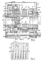
- the apparatus illustrated includes a housing 15 with end walls 16 and 17.
- End wall 17 has a central circular opening 19 for receiving a pipe to be perforated.
- the end wall 16 has a larger circular opening that is aligned with the opening 19 and has as counterbore on the outside.
- a ball bearing 22 is fitted into the counterbore and is retained in position by an end cover 22a.
- the bearing 22 carries the cylindrical sleeve of an adaptor 20.
- the adaptor 20 also has a circular flange fastened to the side face of a sheave 29 by cap screws 29a.
- the adaptor 20 and sheave 29 having a through bore 18 that is the same size as the opening 19 in the end wall 17 and aligns with that opening so that a tube 10 may pass into and out of the apparatus through the openings 18 and 19.
- a stationery ring gear 21 is secured to the inside face of the wall 17 by bolts 21a.
- the gear is aligned with the opening 19 so that the tube 10 can pass through the gear.
- the hub of the gear 21 carries a ball bearing 23, which in turn supports a gear housing 25.
- the housing is sealed to the gear 21 by seals 25a and 25b.
- the gear housing 25 carries three shafts 26a parallel to the gear 21.
- a pinion 26 is keyed to each of the shafts 26a and meshes with the teeth 24 of the ring gear 21.
- Each shaft 26a carries a gear 26b.
- Three idler gears 28 carried by the housing 25 mesh with the gears 26b.
- Three drive bars 30 extend between the gear housing 25 and the sheave 29. The bars are secured to both the housing and the sheave so that these parts rotate as a unit.
- each spindle shaft extends into the gear housing 25 and is keyed to a gear 27 meshing with a respective one of the idlers 28.
- the other end of the spindle shaft is mounted on the sheave 29 by ball bearing 33A.
- each of the spindles 35 has an enlarged cylindrical section 34 that serves as a tool holder.
- This section 34 carries a helical rib 35 on its outer surface and a punch at the location indicated by the circle Y. The punch will be described in more detail in connection with Figures 4 and 5.
- a drive shaft 32 extends through the housing 15, parallel to the tube 10. It is mounted in bearings 32a and 32b in the end walls 16 and 17 respectively.
- the shaft 32 carries sheave 40 aligned with sheave 29. Sheave 40 drives sheave 29 through a series of V belts 31.
- the punch is more clearly illustrated in Figures 4 and 5.
- the body 34 of the spindle 33 has a stepped bore 37a aligned with the rib 35.
- a cylindrical body 37 of the punch fits into the bore 37a and is held in place by a cap screw 38 extending into the bore 37a from the opposite side and threaded into a bore in the inner end of body 37.
- the punch has a cutting head 36 with V shaped cutting edge for cutting rectangular slots in the tube.
- the punch is shown in Figure 6 engaged with the wall of the tube 10 and piercing the tube in the desired manner.
- Figure 7 illustrates an helically corrugated tube 10 with slots 48 produced by the punch.
- the drive shaft 32 is driven from an external power source of any appropriate sort. This drives the sheave 40, the belts 31 and sheave 29. Rotation of sheave 29 acts through drive bar 30 to rotate the gear housing 25. As the sheave 29 and gear housing 25 rotate, the spindles 33 are revolved about the tube 10 extending through the housing.
- the gear train consisting of stationary gear 21, pinions 26 and 26b, idlers 28 and gears 27 rotate the spindles 33 about their respective axes.
- Appropriate selec, tion of the gear ratios insures that the ribs 35 of the spindles 33 will roll on the surface of the tube 10 without slipping, so that the punch will progress around the tube in an epicycloidal path.
- the helical ribs 35 on the spindles 33 will engage with the corrugations of the corrugated tube to advance the tube through the punch.
- the ribs 35 may be annular rather than helical. Helical ribs are required for a pipe with annular corrugations.
Landscapes
- Life Sciences & Earth Sciences (AREA)
- Forests & Forestry (AREA)
- Engineering & Computer Science (AREA)
- Mechanical Engineering (AREA)
- Perforating, Stamping-Out Or Severing By Means Other Than Cutting (AREA)
Claims (7)
Applications Claiming Priority (2)
| Application Number | Priority Date | Filing Date | Title |
|---|---|---|---|
| US33517181A | 1981-12-28 | 1981-12-28 | |
| US335171 | 1989-04-06 |
Publications (2)
| Publication Number | Publication Date |
|---|---|
| EP0083164A1 EP0083164A1 (de) | 1983-07-06 |
| EP0083164B1 true EP0083164B1 (de) | 1986-02-05 |
Family
ID=23310592
Family Applications (1)
| Application Number | Title | Priority Date | Filing Date |
|---|---|---|---|
| EP19820306521 Expired EP0083164B1 (de) | 1981-12-28 | 1982-12-07 | Drehende Stanzvorrichtung |
Country Status (3)
| Country | Link |
|---|---|
| EP (1) | EP0083164B1 (de) |
| CA (1) | CA1187399A (de) |
| DE (1) | DE3269027D1 (de) |
Cited By (1)
| Publication number | Priority date | Publication date | Assignee | Title |
|---|---|---|---|---|
| DE3914779A1 (de) * | 1989-05-05 | 1990-11-08 | Rainer Isolierrohr Drossbach | Verfahren und vorrichtung zum schneiden von schlitzen in rohrfoermige koerper |
Families Citing this family (2)
| Publication number | Priority date | Publication date | Assignee | Title |
|---|---|---|---|---|
| JP4438203B2 (ja) * | 2000-09-12 | 2010-03-24 | 株式会社デンソー | パイプの穴開け方法及び装置 |
| CN112092258A (zh) * | 2020-08-04 | 2020-12-18 | 安徽中宏橡塑有限公司 | 一种再生橡胶加工用边角去除装置 |
Family Cites Families (2)
| Publication number | Priority date | Publication date | Assignee | Title |
|---|---|---|---|---|
| DE2230767C2 (de) * | 1972-06-23 | 1974-08-22 | Wilhelm 8730 Bad Kissingen Hegler | Vorrichtung zum Einschneiden von Öffnungen in Rohre |
| DE2262231C3 (de) * | 1972-12-20 | 1975-10-30 | Ingrid M.A.C. Brussegem B/Bruessel Hermans (Belgien) | Vorrichtung zum Einstanzen von Löchern in Kunststoffrohre |
-
1982
- 1982-12-02 CA CA000416831A patent/CA1187399A/en not_active Expired
- 1982-12-07 DE DE8282306521T patent/DE3269027D1/de not_active Expired
- 1982-12-07 EP EP19820306521 patent/EP0083164B1/de not_active Expired
Cited By (1)
| Publication number | Priority date | Publication date | Assignee | Title |
|---|---|---|---|---|
| DE3914779A1 (de) * | 1989-05-05 | 1990-11-08 | Rainer Isolierrohr Drossbach | Verfahren und vorrichtung zum schneiden von schlitzen in rohrfoermige koerper |
Also Published As
| Publication number | Publication date |
|---|---|
| CA1187399A (en) | 1985-05-21 |
| EP0083164A1 (de) | 1983-07-06 |
| DE3269027D1 (en) | 1986-03-20 |
Similar Documents
| Publication | Publication Date | Title |
|---|---|---|
| US3824886A (en) | Apparatus for cutting apertures in tubes | |
| US4180357A (en) | Apparatus and method for perforating tubing and method of producing part of such apparatus | |
| US4218164A (en) | Apparatus and method for perforating tubing | |
| US4488467A (en) | Apparatus for cutting openings in pipes | |
| EP0332450A2 (de) | Zweiseitig verzahntes Zahnrad, Verfahren zur Erzeugung seines Zahnprofils und damit ausgestattetes Untersetzungs-Differential | |
| US4587874A (en) | Rotary punch | |
| US3656331A (en) | Apparatus for producing annular corrugated tubing | |
| CA1187399A (en) | Rotary cutter assembly | |
| EP0013626B1 (de) | Verfahren und Vorrichtungen zum Lochen von Rohren | |
| US4083273A (en) | Hole punching method and apparatus | |
| US4732065A (en) | Rotary serrated tube punch with internal back-up for a film web and method of punching holes therewith | |
| US2712775A (en) | Machines for manufacturing drills, taps, and other articles | |
| CN217617202U (zh) | 一种能够收集边角料的电机冲片生产用冲压装置 | |
| US3817131A (en) | Apparatus for cutting rings from tubes | |
| US3258263A (en) | Intermittent feeding mechanism for strip material | |
| US5381711A (en) | Apparatus for perforating corrugated tubing | |
| JPH04504984A (ja) | 管状体にスリットを切削するための装置 | |
| JPS6416315A (en) | Unit for tapping | |
| CN213598529U (zh) | 一种可调差速驱动机构 | |
| US6666059B1 (en) | Method and device for rotating and machining bar material | |
| CN213381920U (zh) | 一种塑料管打孔装置 | |
| CN112388728B (zh) | 一种塑料管打孔机 | |
| SU1315173A1 (ru) | Устройство дл безотходной резки труб | |
| JPH0673837B2 (ja) | 穿孔装置 | |
| SU596463A1 (ru) | Устройство дл перфорировани гофрированных пластмассовых труб |
Legal Events
| Date | Code | Title | Description |
|---|---|---|---|
| PUAI | Public reference made under article 153(3) epc to a published international application that has entered the european phase |
Free format text: ORIGINAL CODE: 0009012 |
|
| AK | Designated contracting states |
Designated state(s): DE FR GB IT NL |
|
| 17P | Request for examination filed |
Effective date: 19831210 |
|
| GRAA | (expected) grant |
Free format text: ORIGINAL CODE: 0009210 |
|
| AK | Designated contracting states |
Designated state(s): DE FR GB IT NL |
|
| PG25 | Lapsed in a contracting state [announced via postgrant information from national office to epo] |
Ref country code: IT Free format text: LAPSE BECAUSE OF FAILURE TO SUBMIT A TRANSLATION OF THE DESCRIPTION OR TO PAY THE FEE WITHIN THE PRESCRIBED TIME-LIMIT;WARNING: LAPSES OF ITALIAN PATENTS WITH EFFECTIVE DATE BEFORE 2007 MAY HAVE OCCURRED AT ANY TIME BEFORE 2007. THE CORRECT EFFECTIVE DATE MAY BE DIFFERENT FROM THE ONE RECORDED. Effective date: 19860205 |
|
| REF | Corresponds to: |
Ref document number: 3269027 Country of ref document: DE Date of ref document: 19860320 |
|
| EN | Fr: translation not filed | ||
| PLBI | Opposition filed |
Free format text: ORIGINAL CODE: 0009260 |
|
| 26 | Opposition filed |
Opponent name: HEGLER PLASTIK GMBH Effective date: 19861103 |
|
| NLR1 | Nl: opposition has been filed with the epo |
Opponent name: HEGLER PLASTIK GMBH |
|
| PGFP | Annual fee paid to national office [announced via postgrant information from national office to epo] |
Ref country code: NL Payment date: 19871231 Year of fee payment: 6 |
|
| PGFP | Annual fee paid to national office [announced via postgrant information from national office to epo] |
Ref country code: DE Payment date: 19890221 Year of fee payment: 7 |
|
| RDAG | Patent revoked |
Free format text: ORIGINAL CODE: 0009271 |
|
| STAA | Information on the status of an ep patent application or granted ep patent |
Free format text: STATUS: PATENT REVOKED |
|
| 27W | Patent revoked |
Effective date: 19890807 |
|
| GBPR | Gb: patent revoked under art. 102 of the ep convention designating the uk as contracting state | ||
| NLR2 | Nl: decision of opposition |