EP0083176A2 - Système et dispositif pour la conversion de signaux vidéo en images sur un support d'enregistrement sensible à la lumière - Google Patents
Système et dispositif pour la conversion de signaux vidéo en images sur un support d'enregistrement sensible à la lumière Download PDFInfo
- Publication number
- EP0083176A2 EP0083176A2 EP82306706A EP82306706A EP0083176A2 EP 0083176 A2 EP0083176 A2 EP 0083176A2 EP 82306706 A EP82306706 A EP 82306706A EP 82306706 A EP82306706 A EP 82306706A EP 0083176 A2 EP0083176 A2 EP 0083176A2
- Authority
- EP
- European Patent Office
- Prior art keywords
- signal
- colour
- image
- reference signal
- video
- Prior art date
- Legal status (The legal status is an assumption and is not a legal conclusion. Google has not performed a legal analysis and makes no representation as to the accuracy of the status listed.)
- Granted
Links
Images


Classifications
-
- H—ELECTRICITY
- H04—ELECTRIC COMMUNICATION TECHNIQUE
- H04N—PICTORIAL COMMUNICATION, e.g. TELEVISION
- H04N1/00—Scanning, transmission or reproduction of documents or the like, e.g. facsimile transmission; Details thereof
- H04N1/46—Colour picture communication systems
- H04N1/56—Processing of colour picture signals
- H04N1/60—Colour correction or control
- H04N1/6027—Correction or control of colour gradation or colour contrast
-
- H—ELECTRICITY
- H04—ELECTRIC COMMUNICATION TECHNIQUE
- H04N—PICTORIAL COMMUNICATION, e.g. TELEVISION
- H04N1/00—Scanning, transmission or reproduction of documents or the like, e.g. facsimile transmission; Details thereof
- H04N1/40—Picture signal circuits
- H04N1/40025—Circuits exciting or modulating particular heads for reproducing continuous tone value scales
-
- H—ELECTRICITY
- H04—ELECTRIC COMMUNICATION TECHNIQUE
- H04N—PICTORIAL COMMUNICATION, e.g. TELEVISION
- H04N1/00—Scanning, transmission or reproduction of documents or the like, e.g. facsimile transmission; Details thereof
- H04N1/40—Picture signal circuits
- H04N1/407—Control or modification of tonal gradation or of extreme levels, e.g. background level
- H04N1/4076—Control or modification of tonal gradation or of extreme levels, e.g. background level dependent on references outside the picture
Definitions
- This invention relates to techniques for compensating nonlinearities and introducing predetermined variations in the conversion of electronic signals representing video images to images on photographic media.
- a number of systems are known for generating color and pseudo-color displays from input video signals presented in raster scan format. Some of these systems process and thereafter convert the video signals derived from image scanning into photographic records of the images more precisely than can direct exposure techniques. A number of factors, some readily evident and others more subtle although still important, preclude obtaining true colors and contrasts when direct exposure is used. It need only be noted that photographic media are inherently nonlinear and that photographic dyes are not only of different colors than CRT phosphors but also function subtractively whereas the color image in a CRT is formed additively. These mismatches at the minimum cause loss of true color, saturation and detail.
- Conversion of the information contained in video signals to a photographic image not only requires compensation for these and other factors, but also desirably includes a number of other capabilities. It is desirable for example to be able to process images so as to generate negatives as well as positives, pseudo color as well as true color images, and to adjust contrast, hue and luminance to meet individual preferences.
- the image is recorded under control of the microprocessor, which determines the exposure time and light intensity variations during each image scan. Because, as described in the article, this system enables many adjustments to be made and includes other features such as raster line elimination, it produces photographic images of high color quality and resolution.
- the techniques heretofore used for compensating gamma distortion have used nonlinear amplifiers or other compensating circuits in the transfer path, to attempt to achieve an overall linear response. While such techniques can be utilized to optimize a system under one given set of conditions, i.e. a specific device operating with a particular film, this does not satisfy current needs. At most, only coarse "black stretch” or “white stretch” compensation can be introduced in balancing the image. Furthermore, the precision required in these systems means that the minor differences that exist between successive products coming off an assembly line can introduce excessive variations in signal transfer functions. These product-to-product variations can only be compensated by lengthy and expensive individual tuning procedures. Further, such tuning can correct for only one particular set of conditions and other corrections must remain as approximations.
- Prior art approaches can therefore be seen to be unsuitable for compensating for the full scope of gamma function nonlinearities arising from cathode ray tube, signal transfer path and photographic media characteristics. They also have limited capability for generating negative/positive images or pseudo-color images and prior expedients also offer only limited versatility with regard to contrast adjustment, color enhancement and other types of color manipulation.
- Duration modulation is achieved by comparing the instantaneous amplitude of a video signal to a reference that assumes different levels (preferably, though not necessarily successively) as successive scans are provided, and turning a scanning beam of substantially constant intensity on or off in accordance with the amplitude relationship.
- the rate of change of the reference signal may be controlled by storing digital data representing successive sets of reference values defining a number of different gamma function curves, and selecting one of these sets.
- the digital values of the chosen set control the rate of change of the reference signal throughout the total exposure interval, during which the video signal sequence for the given image is presented repeatedly.
- the changing reference signal is, however, substantially constant during each raster scan interval.
- gamma function compensation may be customized readily for each of a number of copies of a given model by using a reference signal sequence to actuate the CRT, sensing actual signal variations, computing the compensating values, and then adjusting the digital data values in the sequence for a particular gamma function.
- video signals are utilized with a raster scan CRT having a constant intensity writing beam.
- Electronic circuits establish a varying threshold reference that sweeps between maximum and minimum video signal amplitude levels at varying rates within a total exposure interval.
- the rates of change for successive amplitude bands are determined, under microprocessor control, by the stored data, which effectively define a plurality of linked linear segments of varying slope.
- each stored value establishes a pulse sequence having varying periodicity but a fixed total number, with the successive amplitude levels of the threshold being equally spaced.
- the non-linearly varying threshold is generated by continuously converting the accumulating digital counts to an analog signal amplitude.
- a system in accordance with the invention may advantageously be utilized in conjunction with one of the "Videoprint" systems of Image Resource Corporation of Westlake Village, California. In the interests of brevity, only relevant portions of such a system have been depicted in Fig. 1 and will be described hereafter.
- a color video source 10 provides an encoded composite color television signal frame which is to be recorded as an image on a photographic color medium 12 (e.g. transparency, print negative or instant process film) by the system.
- a photographic color medium 12 e.g. transparency, print negative or instant process film
- the color video source 10 may be a video cassette recorder, video tape recorder, video disk system or a storage tube or other device for presenting a single video frame over an interval sufficiently long for the signal to be processed.
- the source 10 could be a data processing display system generating a color image by one of the many techniques that are now in use.
- a composite color television signal is processed to generate separate and successively presented green, blue and red images in what may be called a color image separator or decoder 14.
- the separator 14 extracts, for example, the red picture values for each picture element (pixel) in the display and presents these for as long as the red image is needed.
- the separation function is considerably simplified with a computer graphic display system because any desired display can be presented as a data sequence merely by software control.
- the term "pixel” is used herein for ease of reference in a general sense to denote both discrete points (as in a 512 x 512 matrix display) and successive segments of a continuum (as in a television raster line). It is immaterial in. other words whether discrete digital (or analog) or continuous analog values are used or the displays are of the point or line type.
- Scan circuits 20 operating in synchronism with the presentation of the monocolor image provide constant raster scan repetition on a high precision cathode ray tube 18 during the interval (of the order typically of a few seconds) that is selected for proper exposure of the photographic color medium 12. At typical frame rates the image for each color is thus presented many times during an exposure. It will be appreciated that details of the color image separator 14 and the data processor system which control selection of the exposure interval and switching from one color to another have been omitted for brevity.
- the optical system includes a lens system 21 (shown only generally) and a color filter system 22 that interposes successive and different color filters 24 in the optical path between the face of the CRT 18 and the photographic medium 12.
- the filters 24 are changed under control of the processor as different images are presented, but inasmuch as details are publicly available and not germane to the present invention they need not be further described.
- the "Videoprint" systems currently available use intensity modulation of the writing beam on the CRT 18, together with analog adjustment of the shape of the gamma function curve, in the manner previously described relative to the prior art.
- the system utilizes a microprocessor 30, a stored data system 32, and a pixel duration control 34 which together provide time modulation of individual picture elements with a constant intensity beam.
- a microprocessor 30 a stored data system 32
- a pixel duration control 34 which together provide time modulation of individual picture elements with a constant intensity beam.
- the stored data system 32 may alternatively be incorporated as part of the microprocessor 30 under software control.
- a memory subsystem provides a plurality of stored digital tables 38, each table corresponding to a succession of digital values representing a sequence of slope variations making up an individual gamma correction curve.
- the stored tables 38 may alternatively or additionally be utilized for contrast control, special color effects or control of positive/negative image recording.
- access to the stored tables 38 is controlled by addressing the tables by a curve selection address decoder 40 which is responsive to operative conditions indicated by the microprocessor 30 or by the system operator, who may make manual mode selections or individual adjustments.
- the available modes include microprocessor control of compensation for the individual color being displayed, film type and other variables.
- the address decoder 40 controls stepping from one position in the tables to another, from a start point under control of increment or count group pulses provided in operation of the system, as is described hereinafter.
- a succession of individual values derived from the stored tables 38 are thus supplied to an output or increment value register 42, to indicate the slope of each successive increment of the gamma compensation curve that is being generated.
- a variable rate pulse generator 44 responds to the instantaneous digital value of the register 42 to provide a controlled rate clock output until the register 42 is reset with a new value.
- the variable clock output may be generated in conventional fashion, by converting the register 42 output to an analog signal that controls a variable frequency oscillator, or digital techniques may be utilized to employ the closest submultiple of the microprocessor 30 clock or a separately generated clock. In either event, the output of the variable rate pulse generator 44 is employed to establish a fixed count sequence (e.g. 32 pulses).
- the total duration of the fixed count sequence is determined by the clock rate for that increment. This arrangement also determines the rate of change of one increment of a curve, inasmuch as an output voltage change of varying slope is generated simply by inputting the variable rate pulses to a counter 46 which controls a digital-to-analog converter 48.
- the output of the iigital-to-analog converter 48 is a moving or sweeping threshold signal which changes in slope at regularly 3 paced amplitude steps in accordance with the changes in values provided by the register 42.
- the total duration of each fixed count sequence is established directly by applying the pulses to a preset counter 52 which provides an overflow pulse denoting the occurrence of each group of 32 pulses. This overflow pulse or increment command is provided back to the address decoder 40 so as to shift to the next incremental segment of the selected gamma correction curve.
- the moving threshold signal and the monochrome image signal for a given color from the color image separator 14 comprise the two inputs to the pixel duration control 34.
- a pixel generator 56 responsive to the monochrome image signal (red, green or blue) and to a color subcarrier clock derived from the video circuits of the system provides a constantly varying analog signal level that corresponds to the individual picture elements in the given color image. It will be recognized that the pixel sequences can be continuous or separate in time depending upon the nature of the display and the CRT. In either event, however, a comparison is constantly made between the video component of the monochrome image and the moving threshold, and the writing beam of the CRT 18 is turned on only when the comparator 58 indicates that the video signal amplitude is in excess of the moving threshold at that time.
- the total display interval, T is much greater than the scan time (t) for an individual image on the CRT 18.
- the moving threshold signal sweeps from one limit to another within its range over the interval of many successive CRT rasters, and these limits correspond to the deviation range (from black to white or vice versa) of the video signal. Consequently, for a system in which the threshold starts high and the comparator 58 output causes the on/off control 60 to go on, the writing beam at the CRT 18 is progressively turned on at increasingly darker areas until all gray areas are illuminated just before the exposure interval ends.
- the result is the presentation of a display for the given color in which the duration of exposure of any individual pixel is controllably varied with the gray level for that pixel. All writing on the photographic medium 12 is effected by a constant intensity beam, however.
- the threshold can sweep from the white to the black direction as described, or alternatively can sweep in the opposite direction.
- Image reversal can be obtained by simply operating the on/off control 60 so that the beam is "on” instead of "off” when the threshold exceeds the video signal. Unity gain inversion of the video signal would provide the same effect.
- the pixel comparator 58 and on/off control 60 of Fig. 1 may be provided as shown in Fig. 2 by a single operational amplifier 64 operated in a saturation mode whenever the video signal on one input exceeds the variable threshold level applied on the other input.
- the output of the amplifier 64 is a square wave signal, essentially a time modulated binary digital output, that goes high any time the video signal level exceeds the threshold voltage. With sufficient power, the signal can be used directly for beam intensity control.
- the signal is applied to the on/off control 60 that is responsive to a reference voltage that may be adjusted in the event that it is desired to change the level at which the constant intensity beam writes.
- a like control can be achieved using a control grid in the CRT or some other form of beam intensity control.
- Fig. 3 depicts the relationship of the different signals when scanning an arbitrary chosen raster line for a given scene in the arrangement of Fig. 1.
- the video scene at A in Fig. 3 is intercepted by a scanning raster line that goes through areas of light, gray and dark at different times. For the chosen line location, this generates the video signal indicated at B in Fig. 3, with the intermediate starting level representing the sky, the highest intensity level representing the snow on the mountain, the mountain itself being essentially gray and the foreground pine tree being essentially black.
- These levels are depicted in Fig. 4 relative to a standard deviation of 0.714 volts in the video signal between black and white, and a variation on the IRE scale of +7.5 to 100.
- the standards specify that zero to 100 represents the range of the pedestal or blanking level to the white level but -40 is used-as the synchronizing signal level. Consequently, as shown in curve C of Fig. 3, the time modulated writing beam is fully on whenever the video signal exceeds the threshold, no matter by how much.
- the moving threshold does not differ to any significant extent between the start and end of a single raster sweep. There is a slight difference between the start and end of a frame, which at the most provides a virtually indiscernible gradation in the vertical image direction. However, this can be compensated in a number of ways including stepping the threshold in the blanking region or introducing a slight ramp function into the intensity control.
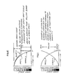
- the curves A, B and C of Fig. 5 depict the relationship between the threshold level and the length of time each gray scale level is present on the CRT, and then the correspondence between this exposure time and the resultant density on the photographic film being exposed.
- the significant parameters are all directly interrelated inasmuch as the distance B on curve A is directly determinative of the exposure time B on the CRT, which in turn is directly determinative of the film density because exposure energy is held constant.
- Gamma corrections can be used in a wide variety of ways as depicted in Figs. 6-11.
- a normalized gamma curve is shown by the solid line in Fig. 6, which is the only Figure showing the interconnected sequence of varying slope increments which make up the curve.
- "White stretch” variations may be introduced using deviations from the normalized curve as shown by the dotted and dot-dash lines in Fig. 6.
- Increasing the black detail, known as "black stretch” is achieved by the family of curves shown in Fig. 7.
- the curves are shown as two separate families for. clarity only inasmuch as the normalized solid line curves are the same.
- the gamma compensation curves may also be used to vary contrast, as depicted in Figs. 8 and 9, which demonstrate decrease and increase of contrast respectively. It can be seen that the steepest slopes on the decreased contrast curves (Fig. 8) are at some inflection position in the gray scale region so that exposure time throughout the gray scale is largely the same and contrast is thus diminished.
- the curves for increased contrast (Fig. 9) deviate oppositely from the normalized curve with minimum rate of change being used in the gray scale region about the inflection position. As noted, the location of the inflection line can be placed at any selected region along the time axis.
- the arbitrary variations that are feasible in the compensation curves enable a wide range of color effects to be achieved in systems in accordance with the invention.
- pseudo-color effects in one or more colors can be obtained by artificial variation of the curves for one or more colors.
- three different color effects are obtained in a color film record.
- the normal gray scales are maintained, giving bright, composite color areas.
- the red and green combine in this specific subrange to provide a yellow image.
- a further benefit of systems in accordance with the invention derives from the fact that the characteristics of each production unit can readily be identified and compensated to a predetermined standard.
- An external computer or the microprocessor in the system can be utilized in calculating the precise compensation curves needed for a standardized output.
- a given excitation signal is applied to the CRT.
- One or more sensors disposed in the optical path from the CRT measure the actual light output (brightness) and the signal duration for a given video level input. Readings may be taken at all the different levels at which the sweeping threshold curve changes slope, e.g. at video input level IRE units of 10, 20...100.
- each production unit can provide normalized light outputs regardless of variations from nominal values within the different production units coming off an assembly line.
Landscapes
- Engineering & Computer Science (AREA)
- Multimedia (AREA)
- Signal Processing (AREA)
- Transforming Light Signals Into Electric Signals (AREA)
- Picture Signal Circuits (AREA)
- Processing Of Color Television Signals (AREA)
- Color Television Systems (AREA)
- Facsimile Scanning Arrangements (AREA)
Priority Applications (1)
| Application Number | Priority Date | Filing Date | Title |
|---|---|---|---|
| AT82306706T ATE30823T1 (de) | 1981-12-21 | 1982-12-15 | System und geraet zur umwandlung von videosignalen in bilder auf einem lichtempfindlichen aufzeichnungstraeger. |
Applications Claiming Priority (2)
| Application Number | Priority Date | Filing Date | Title |
|---|---|---|---|
| US333120 | 1981-12-21 | ||
| US06/333,120 US4473849A (en) | 1981-12-21 | 1981-12-21 | System and apparatus for conversion of video signals to film images |
Publications (3)
| Publication Number | Publication Date |
|---|---|
| EP0083176A2 true EP0083176A2 (fr) | 1983-07-06 |
| EP0083176A3 EP0083176A3 (en) | 1985-07-31 |
| EP0083176B1 EP0083176B1 (fr) | 1987-11-11 |
Family
ID=23301364
Family Applications (1)
| Application Number | Title | Priority Date | Filing Date |
|---|---|---|---|
| EP82306706A Expired EP0083176B1 (fr) | 1981-12-21 | 1982-12-15 | Système et dispositif pour la conversion de signaux vidéo en images sur un support d'enregistrement sensible à la lumière |
Country Status (7)
| Country | Link |
|---|---|
| US (1) | US4473849A (fr) |
| EP (1) | EP0083176B1 (fr) |
| JP (1) | JPS58111586A (fr) |
| AT (1) | ATE30823T1 (fr) |
| AU (1) | AU551349B2 (fr) |
| CA (1) | CA1196088A (fr) |
| DE (1) | DE3277678D1 (fr) |
Cited By (6)
| Publication number | Priority date | Publication date | Assignee | Title |
|---|---|---|---|---|
| EP0137768A4 (fr) * | 1982-01-21 | 1987-05-13 | Polaroid Corp | Copieur couleur a haute resolution utilisant un ecran cathodique noir et blanc. |
| WO1988010041A1 (fr) * | 1987-06-03 | 1988-12-15 | Eastman Kodak Co | Traitement de signaux pour imprimante thermique |
| EP0290976A3 (fr) * | 1987-05-09 | 1991-01-30 | Ricoh Company, Ltd | Système de commande de la densité pour un appareil à copier numérique |
| WO1991003903A1 (fr) * | 1989-09-11 | 1991-03-21 | Eastman Kodak Company | Circuit numerique creant des effets speciaux video dans des zones definies |
| EP0717551A3 (fr) * | 1986-02-14 | 1996-10-09 | Canon Kk | Dispositif de traitement d'image |
| EP2312825A3 (fr) * | 2009-10-14 | 2012-12-05 | Samsung Electronics Co., Ltd. | Procédé et appareil pour contrôler la source lumineuse dans un appareil de balayage d'images |
Families Citing this family (34)
| Publication number | Priority date | Publication date | Assignee | Title |
|---|---|---|---|---|
| US4627004A (en) * | 1982-10-12 | 1986-12-02 | Image Resource Corporation | Color image recording system and method for computer-generated displays |
| JPS5983150A (ja) * | 1982-11-04 | 1984-05-14 | Fuji Photo Film Co Ltd | 感光材料階調補正方法 |
| AU577046B2 (en) * | 1983-06-08 | 1988-09-15 | Mitsubishi Denki Kabushiki Kaisha | A printer for a television receiver |
| JPS60263139A (ja) * | 1984-06-12 | 1985-12-26 | Nippon Abionikusu Kk | 画像記録装置 |
| US4704699A (en) * | 1984-06-25 | 1987-11-03 | Bell & Howell Company | Digital film recorder, peripheral, and method for color hardcopy production |
| US4771342A (en) * | 1985-05-01 | 1988-09-13 | Emf Partners, Ltd. | Method and apparatus for enhancing video-recorded images to film grade quality |
| US4688104A (en) * | 1985-09-16 | 1987-08-18 | Eastman Kodak Company | Apparatus for producing a full resolution color photographic copy of a color video signal |
| US4694356A (en) * | 1985-09-16 | 1987-09-15 | Eastman Kodak Company | Modification of color component video signals to compensate for decreasing white sensitivity of photographic element |
| US4685000A (en) * | 1985-09-16 | 1987-08-04 | Eastman Kodak Company | Inhibition of exposure in a video printer upon loss of color filter sync |
| US5010414A (en) * | 1985-11-27 | 1991-04-23 | Clapp Roy A | Process eliminating the use of a master positive film for making a duplicate negative of a color motion picture |
| US4742397A (en) * | 1986-01-16 | 1988-05-03 | Polaroid Corporation | System and method for adjusting image brightness in electronic printer |
| JPH065932B2 (ja) * | 1986-05-28 | 1994-01-19 | 富士写真フイルム株式会社 | 画像記録装置 |
| US4827434A (en) * | 1986-07-22 | 1989-05-02 | Hewlett-Packard Company | Method for time modulation in vector film recorders |
| JPS6334593A (ja) * | 1986-07-30 | 1988-02-15 | ホシデン株式会社 | 多階調表示方法 |
| DE3629416C2 (de) * | 1986-08-29 | 1994-02-17 | Agfa Gevaert Ag | Verfahren und Vorrichtung zum punkt- und zeilenweisen Kopieren von Farbbildern |
| US4855940A (en) * | 1987-01-16 | 1989-08-08 | Polaroid Corporation | Method of and system for computer graphic photography |
| US4943861A (en) * | 1987-03-03 | 1990-07-24 | Analogic Corporation | Apparatus and method for exposing photosensitive recording media with digital image data |
| JPH0786643B2 (ja) * | 1987-06-05 | 1995-09-20 | 富士写真フイルム株式会社 | ビデオプリンタのシエーディング補正方法 |
| JPS63309077A (ja) * | 1987-06-11 | 1988-12-16 | Seikosha Co Ltd | ビデオプリンタ |
| DE3820799C2 (de) * | 1987-06-19 | 1996-03-14 | Fuji Photo Film Co Ltd | Fotografisches Kopiergerät |
| GB2211045B (en) * | 1987-10-10 | 1991-08-21 | Marconi Co Ltd | Linearity adjusting circuit |
| US5018085A (en) * | 1988-06-16 | 1991-05-21 | Hallmark Cards, Inc. | Color printing system usable for reproduction of computer-generated images |
| US4999791A (en) * | 1988-12-23 | 1991-03-12 | Schumann Robert W | Computer graphics color film recording method and apparatus |
| US5313283A (en) * | 1989-04-21 | 1994-05-17 | Camtronics, Ltd. | System and method for controlling exposure format for an apparatus for exposing photographic film with image data |
| JPH04304095A (ja) * | 1991-03-31 | 1992-10-27 | Sony Corp | 画像信号変換装置 |
| GB2271239B (en) * | 1992-09-29 | 1996-06-19 | Sony Broadcast & Communication | Video to film conversion |
| US6791576B1 (en) | 2000-02-23 | 2004-09-14 | Neomagic Corp. | Gamma correction using double mapping with ratiometrically-related segments of two different ratios |
| EP1497693A4 (fr) * | 2002-04-25 | 2007-02-14 | Pixar | Enregistreur de film numerique a ecran plat |
| US20040184762A1 (en) * | 2003-03-20 | 2004-09-23 | Pixar | Flat panel digital film recorder and method |
| US7787010B2 (en) * | 2003-03-20 | 2010-08-31 | Pixar | Video to film flat panel digital recorder and method |
| US7576830B2 (en) * | 2003-03-20 | 2009-08-18 | Pixar | Configurable flat panel image to film transfer method and apparatus |
| US20040202445A1 (en) * | 2003-03-20 | 2004-10-14 | Pixar | Component color flat panel digital film recorder and method |
| US7463821B2 (en) * | 2003-03-20 | 2008-12-09 | Pixar | Flat panel image to film transfer method and apparatus |
| US7366349B2 (en) * | 2004-11-02 | 2008-04-29 | Pixar | Two-dimensional array spectroscopy method and apparatus |
Family Cites Families (2)
| Publication number | Priority date | Publication date | Assignee | Title |
|---|---|---|---|---|
| NL51681C (fr) * | 1938-04-12 | |||
| GB1262284A (en) * | 1968-03-13 | 1972-02-02 | Agfa Gevaert | Improvements relating to the reproduction of multicolor scenes and prints in multicolour television |
-
1981
- 1981-12-21 US US06/333,120 patent/US4473849A/en not_active Expired - Fee Related
-
1982
- 1982-11-24 AU AU90839/82A patent/AU551349B2/en not_active Ceased
- 1982-11-26 CA CA000416525A patent/CA1196088A/fr not_active Expired
- 1982-12-15 DE DE8282306706T patent/DE3277678D1/de not_active Expired
- 1982-12-15 AT AT82306706T patent/ATE30823T1/de not_active IP Right Cessation
- 1982-12-15 EP EP82306706A patent/EP0083176B1/fr not_active Expired
- 1982-12-20 JP JP57222218A patent/JPS58111586A/ja active Pending
Cited By (7)
| Publication number | Priority date | Publication date | Assignee | Title |
|---|---|---|---|---|
| EP0137768A4 (fr) * | 1982-01-21 | 1987-05-13 | Polaroid Corp | Copieur couleur a haute resolution utilisant un ecran cathodique noir et blanc. |
| EP0717551A3 (fr) * | 1986-02-14 | 1996-10-09 | Canon Kk | Dispositif de traitement d'image |
| EP0290976A3 (fr) * | 1987-05-09 | 1991-01-30 | Ricoh Company, Ltd | Système de commande de la densité pour un appareil à copier numérique |
| WO1988010041A1 (fr) * | 1987-06-03 | 1988-12-15 | Eastman Kodak Co | Traitement de signaux pour imprimante thermique |
| WO1991003903A1 (fr) * | 1989-09-11 | 1991-03-21 | Eastman Kodak Company | Circuit numerique creant des effets speciaux video dans des zones definies |
| EP2312825A3 (fr) * | 2009-10-14 | 2012-12-05 | Samsung Electronics Co., Ltd. | Procédé et appareil pour contrôler la source lumineuse dans un appareil de balayage d'images |
| US8462402B2 (en) | 2009-10-14 | 2013-06-11 | Samsung Electronics Co., Ltd. | Method and apparatus for controlling light source in image scanning apparatus |
Also Published As
| Publication number | Publication date |
|---|---|
| AU551349B2 (en) | 1986-04-24 |
| EP0083176A3 (en) | 1985-07-31 |
| JPS58111586A (ja) | 1983-07-02 |
| AU9083982A (en) | 1983-06-30 |
| DE3277678D1 (en) | 1987-12-17 |
| EP0083176B1 (fr) | 1987-11-11 |
| CA1196088A (fr) | 1985-10-29 |
| US4473849A (en) | 1984-09-25 |
| ATE30823T1 (de) | 1987-11-15 |
Similar Documents
| Publication | Publication Date | Title |
|---|---|---|
| EP0083176B1 (fr) | Système et dispositif pour la conversion de signaux vidéo en images sur un support d'enregistrement sensible à la lumière | |
| US4438453A (en) | Constant light greyscale generator for CRT color camera system | |
| US4912558A (en) | Optical image to video transfer system having enhanced resolution and contrast for dark areas of the image | |
| US5390036A (en) | Color image reproduction of scenes with preferential tone mapping | |
| US5375000A (en) | Method and apparatus for generating representation of an image from a transparency | |
| US4639769A (en) | Modifying color digital images | |
| US5115229A (en) | Method and system in video image reproduction | |
| JPH0355078B2 (fr) | ||
| EP0620678B1 (fr) | Procédé et appareil de traitement d'image | |
| CA2036100C (fr) | Appareil corrigeant la gradation de l'image transmise | |
| US4158859A (en) | Automatic control of iris and clamping voltage in video signal generator | |
| US5619230A (en) | System and method for real-time image display palette mapping | |
| US5539459A (en) | Optimal tone scale mapping in electronic cameras | |
| US5387929A (en) | Method and apparatus for subject image tracking in high definition film-to-video color correction | |
| US4706131A (en) | Photographic copier image contrast control | |
| US4281340A (en) | Horizontal scanning rate correction apparatus for beam index color cathode-ray tube | |
| EP0604518B1 (fr) | Systeme d'ombrage a signal de commande | |
| US5303056A (en) | Dynamic gain correction for CRT printing | |
| WO2001078368A2 (fr) | Systeme et procede de correspondance de couleurs bidirectionnelle pour films et video | |
| JPS61157191A (ja) | ビデオプリンタ装置 | |
| JP2610021B2 (ja) | 画像出力装置のシェーディング補正装置 | |
| JP2545261B2 (ja) | 画像処理方法 | |
| EP0104019A1 (fr) | Compensation de défaut d'image | |
| JPS62188552A (ja) | 画像処理装置 | |
| JPH03226199A (ja) | コンバーゼンス調整方法 |
Legal Events
| Date | Code | Title | Description |
|---|---|---|---|
| PUAI | Public reference made under article 153(3) epc to a published international application that has entered the european phase |
Free format text: ORIGINAL CODE: 0009012 |
|
| AK | Designated contracting states |
Designated state(s): AT BE CH DE FR IT LI NL SE |
|
| PUAL | Search report despatched |
Free format text: ORIGINAL CODE: 0009013 |
|
| AK | Designated contracting states |
Designated state(s): AT BE CH DE FR IT LI NL SE |
|
| 17P | Request for examination filed |
Effective date: 19850612 |
|
| 17Q | First examination report despatched |
Effective date: 19860618 |
|
| GRAA | (expected) grant |
Free format text: ORIGINAL CODE: 0009210 |
|
| AK | Designated contracting states |
Kind code of ref document: B1 Designated state(s): AT BE CH DE FR IT LI NL SE |
|
| REF | Corresponds to: |
Ref document number: 30823 Country of ref document: AT Date of ref document: 19871115 Kind code of ref document: T |
|
| ITF | It: translation for a ep patent filed | ||
| REF | Corresponds to: |
Ref document number: 3277678 Country of ref document: DE Date of ref document: 19871217 |
|
| PGFP | Annual fee paid to national office [announced via postgrant information from national office to epo] |
Ref country code: NL Payment date: 19871231 Year of fee payment: 6 |
|
| ET | Fr: translation filed | ||
| PLBE | No opposition filed within time limit |
Free format text: ORIGINAL CODE: 0009261 |
|
| STAA | Information on the status of an ep patent application or granted ep patent |
Free format text: STATUS: NO OPPOSITION FILED WITHIN TIME LIMIT |
|
| 26N | No opposition filed | ||
| PG25 | Lapsed in a contracting state [announced via postgrant information from national office to epo] |
Ref country code: AT Effective date: 19881215 |
|
| PG25 | Lapsed in a contracting state [announced via postgrant information from national office to epo] |
Ref country code: SE Effective date: 19881216 |
|
| PG25 | Lapsed in a contracting state [announced via postgrant information from national office to epo] |
Ref country code: LI Effective date: 19881231 Ref country code: CH Effective date: 19881231 Ref country code: BE Effective date: 19881231 |
|
| BERE | Be: lapsed |
Owner name: IMAGE RESOURCE CORP. Effective date: 19881231 |
|
| PG25 | Lapsed in a contracting state [announced via postgrant information from national office to epo] |
Ref country code: NL Effective date: 19890701 |
|
| NLV4 | Nl: lapsed or anulled due to non-payment of the annual fee | ||
| PG25 | Lapsed in a contracting state [announced via postgrant information from national office to epo] |
Ref country code: FR Free format text: LAPSE BECAUSE OF NON-PAYMENT OF DUE FEES Effective date: 19890831 |
|
| REG | Reference to a national code |
Ref country code: CH Ref legal event code: PL |
|
| PG25 | Lapsed in a contracting state [announced via postgrant information from national office to epo] |
Ref country code: DE Effective date: 19890901 |
|
| REG | Reference to a national code |
Ref country code: FR Ref legal event code: ST |
|
| EUG | Se: european patent has lapsed |
Ref document number: 82306706.1 Effective date: 19891205 |