EP0083306A1 - Procédé et dispositif pour la régulation d'au moins une bobine de compensation dans un réseau polyphasé - Google Patents
Procédé et dispositif pour la régulation d'au moins une bobine de compensation dans un réseau polyphasé Download PDFInfo
- Publication number
- EP0083306A1 EP0083306A1 EP82810553A EP82810553A EP0083306A1 EP 0083306 A1 EP0083306 A1 EP 0083306A1 EP 82810553 A EP82810553 A EP 82810553A EP 82810553 A EP82810553 A EP 82810553A EP 0083306 A1 EP0083306 A1 EP 0083306A1
- Authority
- EP
- European Patent Office
- Prior art keywords
- network
- current
- quenching coil
- line
- sum
- Prior art date
- Legal status (The legal status is an assumption and is not a legal conclusion. Google has not performed a legal analysis and makes no representation as to the accuracy of the status listed.)
- Granted
Links
- 238000000034 method Methods 0.000 title claims abstract description 14
- 238000004804 winding Methods 0.000 claims abstract description 4
- 238000010791 quenching Methods 0.000 claims description 47
- 230000000171 quenching effect Effects 0.000 claims description 47
- 239000013598 vector Substances 0.000 claims description 15
- 230000001105 regulatory effect Effects 0.000 claims description 5
- 238000002955 isolation Methods 0.000 claims description 4
- 238000006243 chemical reaction Methods 0.000 claims description 2
- 230000002123 temporal effect Effects 0.000 claims description 2
- 230000001939 inductive effect Effects 0.000 abstract 2
- 230000007935 neutral effect Effects 0.000 abstract 1
- 239000003990 capacitor Substances 0.000 description 1
- 239000011435 rock Substances 0.000 description 1
Images

Classifications
-
- H—ELECTRICITY
- H02—GENERATION; CONVERSION OR DISTRIBUTION OF ELECTRIC POWER
- H02H—EMERGENCY PROTECTIVE CIRCUIT ARRANGEMENTS
- H02H9/00—Emergency protective circuit arrangements for limiting excess current or voltage without disconnection
- H02H9/08—Limitation or suppression of earth fault currents, e.g. Petersen coil
Definitions
- this automatic quenching coil regulation is blocked because it can no longer measure the resonance curve.
- the resonance voltage is suddenly increased to a high value, e.g. to 9000 volts.
- the resonance voltage reaches the level of the phase voltage, there is no longer any indication of the regulation.
- the invention has for its object to eliminate the disadvantages of the known and to provide a method and a device for regulating at least one quenching coil in a quenched multiphase network, in which the scanning of the voltage is not necessary and which also for arrangements with several busbars or Ensure the correct regulation of at least one quenching coil, even if there is not enough full closure, and several quenching coils.
- a default value is determined for the regulation of the quenching coil in the healthy network, which corresponds to the sum of the default values for the lines of the network, that this default value, which forms the target value, with that via an angle transmitter according to the position the actual value supplied to the quenching coil is compared and that the control of the quenching coil is derived from this comparison of the actual and target values.
- the advantage of the invention can be seen in the fact that the regulation of the quenching coil is practically given by the default values and that there is no need to use a scanning of the voltage curve.
- the setpoint is expediently influenced in a summing amplifier SV with an earth fault criterion EK.
- the subject matter of the invention is thus functional even when an earth fault occurs.
- the default value of each line is set at coding switches, the default value for at least one line being set to a percentage of the target value for the resonance case.
- the quenching coil is set in the healthy network by a factor of 0.8 to 1.2 and the desired under or over compensation is thus achieved.
- the capacitive current in the network to adjust the regulation of the quenching coil L according to the equation is determined, with Ic the current in the event of a ground fault with a low-resistance fault, I LO the current of the quenching coil L in a healthy network, U LO the voltage in the quenching coil L in a healthy network and U over ⁇ 3 the phase voltage in a healthy network .
- the earth fault criterion is derived from a selective earth fault indicator, the sums of the currents of the three phases in the individual lines being recorded using a summation current transformer in each case, that the vector directions of the secondary currents of the summation current transformers of the individual lines are compared and then accordingly the change in the vector direction of the sum of the current in a certain line, it is determined that the earth fault is in this line.
- the selective earth fault indicator described is reliably functional. All capacitive currents in the healthy lines have the same direction because all remaining network capacities are connected to the same transformer voltage.
- the currents measured via the summation current transformers of the healthy lines thus form vectors which run in parallel in the same direction.
- the faulty line leads to the fault location in the deleted network in addition to the capacitive current le flowing active current.
- the vector of the secondary current of this summation current transformer has a different direction and encloses a certain angle with the vectors of the currents of the healthy lines.
- the zero crossings of every second half-wave of the sum of the current of each line generate square-wave pulses, the temporal shifts of which are compared with a setpoint value taken from a network map using a flip-flop circuit, after which, according to the change in the vector direction, the sum of the current in a specific one Line is determined that the earth fault is in this line.
- the device for carrying out the method is expediently designed in such a way that a comparator is connected on the one hand to a digital-to-analog converter with associated coding switches via a summing amplifier with variable gain and on the other hand an angle transmitter indicating the setting of the quenching coil, the comparator being connected via a relay arrangement is connected to the motor drive of the quenching coil.
- This switching arrangement ensures good functioning of the device and is structurally simple and therefore also economical.
- the Relay arrangement with a manual control mode.
- this solution also enables manual intervention in the otherwise automatic regulation of the quenching coil.
- a sum current transformer that detects all three phases is arranged in each line of the network, and secondary windings of this sum current transformer are connected to an electronic device for determining the vector angle of the sums of the currents in individual lines.
- the electronic device for determining the vector angle of the sums of the currents in the individual lines is connected to an alarm panel.
- the summation current transformer is advantageously a conversion transformer.
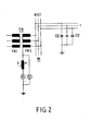
- a transformer TR has a primary side TR1 and a secondary side TR2 in star connection.
- the Zero point of the secondary side TR2 is grounded via an erase coil L, the outputs of the secondary side TR2 are connected to the busbar W of the phases R, S, T and thus also to the associated three-phase lines 1, 2, 3 of the network.
- Each of the three lines 1, 2, 3 is provided with a total current transformer S1, S2, S3.
- the currents in the summation current transformers Sr to S3 are designated by ⁇ I S1 to EI S3 .
- the capacitances CE between lines 1, 2, 3 and the earth are shown symbolically as capacitors.
- An earth fault E with capacitive and ohmic current is shown in this example between the phase T of line 3 and the earth.
- the device according to the invention for regulating at least one quenching coil L in a quenched multiphase network is shown.
- three digital-to-analog converters DA1 to DA3 are assigned to lines 1 to 3, the further lines 4 to, for example, 14 and the further digital-to-analog converters 4 to, for example, digital-to-analog converter 14 not being shown in the drawing are.
- These digital-to-analog converters DA1 to DA3 operate in the range 0 to 99%.
- Each of these converters is connected to two coding switches. These coding switches are each intended for "tens" and "one".
- the first digital-to-analog converter DA1 thus shows 10%
- the sum of all values for eg 14 lines is 100%.
- These three digital-to-analog converters are connected to a summing amplifier SV which is connected to the earth fault criterion EK and which is further connected to a comparator VG.
- the setting of the quenching coil L is conducted into the comparator VG via an angle transmitter WT and a galvanic isolation GT.
- the comparator VG controls a relay arrangement RA, which is connected to a motor drive M. This motor drive M is used to set the quenching coil L.
- the relay arrangement RA can also work in manual mode. This possibility is indicated by the arrow H.
- the comparator VG with the summing amplifier SV, with the earth fault criterion EK and and with the relay arrangement RA form the actual quenching coil regulation LR. The operation of this arrangement has already been described above.
- the gain of the summing amplifier SV is influenced by the earth fault criterion EK.
- a line in this case line 1, is manually switched to a busbar W separately.
- This switching arrangement is used to determine the capacitive currents in the network for setting the automatic quenching coil regulation.
- the capacitive currents of the individual lines are entered as percentages in the automatic system.
- the quenching coil L is set to resonance, i.e. to the maximum of the voltage on the quenching coil L, and now reads the current on the calibrated quenching coil position scale.
- the automatic regulation according to the present invention therefore has two advantages in particular: in a system with a plurality of busbars, the automatics cannot influence one another and the setting criterion is not lost in the event of an earth fault, and thus disconnected power supplies are readjusted.
Landscapes
- Testing Of Short-Circuits, Discontinuities, Leakage, Or Incorrect Line Connections (AREA)
Priority Applications (1)
| Application Number | Priority Date | Filing Date | Title |
|---|---|---|---|
| AT82810553T ATE18833T1 (de) | 1981-12-22 | 1982-12-20 | Verfahren und vorrichtung zur regulierung wenigstens einer loeschspule in einem mehrphasigen netz. |
Applications Claiming Priority (4)
| Application Number | Priority Date | Filing Date | Title |
|---|---|---|---|
| CH818381 | 1981-12-22 | ||
| CH8183/81 | 1981-12-22 | ||
| CH720182 | 1982-12-10 | ||
| CH7201/82 | 1982-12-10 |
Publications (2)
| Publication Number | Publication Date |
|---|---|
| EP0083306A1 true EP0083306A1 (fr) | 1983-07-06 |
| EP0083306B1 EP0083306B1 (fr) | 1986-03-26 |
Family
ID=25700926
Family Applications (1)
| Application Number | Title | Priority Date | Filing Date |
|---|---|---|---|
| EP19820810553 Expired EP0083306B1 (fr) | 1981-12-22 | 1982-12-20 | Procédé et dispositif pour la régulation d'au moins une bobine de compensation dans un réseau polyphasé |
Country Status (2)
| Country | Link |
|---|---|
| EP (1) | EP0083306B1 (fr) |
| DE (1) | DE3270183D1 (fr) |
Cited By (7)
| Publication number | Priority date | Publication date | Assignee | Title |
|---|---|---|---|---|
| FR2616228A1 (fr) * | 1987-06-04 | 1988-12-09 | Merlin Gerin | Dispositif de controle et de mesure de l'isolement d'un reseau electrique |
| WO1992018872A1 (fr) * | 1991-04-19 | 1992-10-29 | Elektro-Bau Ag | Procede de detection d'un circuit derive sujet a une perte a la terre dans un reseau d'alimentation ou de distribution electrique |
| AT404072B (de) * | 1995-02-28 | 1998-08-25 | Haefely Trench Austria Gmbh | Verfahren zur erkennung eines einpoligen erdschlusses in einem drehstromnetz |
| RU2180462C2 (ru) * | 2000-04-20 | 2002-03-10 | Томский политехнический университет | Устройство для измерения расстройки компенсации емкостного тока замыкания на землю |
| CN107340408A (zh) * | 2017-07-26 | 2017-11-10 | 国网河南省电力公司洛阳供电公司 | 一种消弧线圈调试用电容电流发生器 |
| CN112858832A (zh) * | 2019-11-12 | 2021-05-28 | 安徽帕维尔智能技术有限公司 | 一种基于消弧线圈接地系统的大电流选线方法 |
| CN113341246A (zh) * | 2021-05-24 | 2021-09-03 | 国网陕西省电力公司西安供电公司 | 基于电容校准的消弧线圈测试装置及测试方法 |
Families Citing this family (2)
| Publication number | Priority date | Publication date | Assignee | Title |
|---|---|---|---|---|
| CN106802361B (zh) * | 2017-02-21 | 2019-03-29 | 国家电网公司 | 一种配网混连接地运行的电容电流测量方法及系统 |
| CN111030063B (zh) * | 2019-12-09 | 2022-02-01 | 中国南方电网有限责任公司超高压输电公司检修试验中心 | 一种分段时域电容电流补偿方法 |
Citations (5)
| Publication number | Priority date | Publication date | Assignee | Title |
|---|---|---|---|---|
| DE399136C (de) * | 1920-04-16 | 1924-07-26 | Asea Ab | Selbsttaetig veraenderliche Nullpunktdrosselspule fuer Hochspannungsnetze |
| DE760151C (de) * | 1941-08-13 | 1954-02-22 | Brown Ag | Einrichtung zur selbsttaetigen Einstellung einer zum Erdschlussschutz eines Wechselstromnetzes dienenden Loeschinduktivitaet bei AEnderung der Teilkapazitaet des Netzes gegen Erde |
| FR1057276A (fr) * | 1952-05-23 | 1954-03-08 | Merlin Gerin | Détecteur sélectif de défauts de réseau |
| FR2161752A1 (fr) * | 1971-10-27 | 1973-07-13 | Edf | |
| DE2400527A1 (de) * | 1973-01-08 | 1974-08-15 | Knudsen Nordisk Elect | Verfahren zur ermittlung von isolationsfehlern an elektrischen verteilungsnetzen |
-
1982
- 1982-12-20 EP EP19820810553 patent/EP0083306B1/fr not_active Expired
- 1982-12-20 DE DE8282810553T patent/DE3270183D1/de not_active Expired
Patent Citations (5)
| Publication number | Priority date | Publication date | Assignee | Title |
|---|---|---|---|---|
| DE399136C (de) * | 1920-04-16 | 1924-07-26 | Asea Ab | Selbsttaetig veraenderliche Nullpunktdrosselspule fuer Hochspannungsnetze |
| DE760151C (de) * | 1941-08-13 | 1954-02-22 | Brown Ag | Einrichtung zur selbsttaetigen Einstellung einer zum Erdschlussschutz eines Wechselstromnetzes dienenden Loeschinduktivitaet bei AEnderung der Teilkapazitaet des Netzes gegen Erde |
| FR1057276A (fr) * | 1952-05-23 | 1954-03-08 | Merlin Gerin | Détecteur sélectif de défauts de réseau |
| FR2161752A1 (fr) * | 1971-10-27 | 1973-07-13 | Edf | |
| DE2400527A1 (de) * | 1973-01-08 | 1974-08-15 | Knudsen Nordisk Elect | Verfahren zur ermittlung von isolationsfehlern an elektrischen verteilungsnetzen |
Cited By (11)
| Publication number | Priority date | Publication date | Assignee | Title |
|---|---|---|---|---|
| FR2616228A1 (fr) * | 1987-06-04 | 1988-12-09 | Merlin Gerin | Dispositif de controle et de mesure de l'isolement d'un reseau electrique |
| EP0297933A1 (fr) * | 1987-06-04 | 1989-01-04 | Merlin Gerin | Dispositif de contrôle et de mesure de l'isolement d'un réseau électrique |
| US4896115A (en) * | 1987-06-04 | 1990-01-23 | Merlin Gerin | Electrical network insulation monitoring and measuring device |
| WO1992018872A1 (fr) * | 1991-04-19 | 1992-10-29 | Elektro-Bau Ag | Procede de detection d'un circuit derive sujet a une perte a la terre dans un reseau d'alimentation ou de distribution electrique |
| AT404072B (de) * | 1995-02-28 | 1998-08-25 | Haefely Trench Austria Gmbh | Verfahren zur erkennung eines einpoligen erdschlusses in einem drehstromnetz |
| RU2180462C2 (ru) * | 2000-04-20 | 2002-03-10 | Томский политехнический университет | Устройство для измерения расстройки компенсации емкостного тока замыкания на землю |
| CN107340408A (zh) * | 2017-07-26 | 2017-11-10 | 国网河南省电力公司洛阳供电公司 | 一种消弧线圈调试用电容电流发生器 |
| CN107340408B (zh) * | 2017-07-26 | 2023-06-09 | 国网河南省电力公司洛阳供电公司 | 一种消弧线圈调试用电容电流发生器 |
| CN112858832A (zh) * | 2019-11-12 | 2021-05-28 | 安徽帕维尔智能技术有限公司 | 一种基于消弧线圈接地系统的大电流选线方法 |
| CN113341246A (zh) * | 2021-05-24 | 2021-09-03 | 国网陕西省电力公司西安供电公司 | 基于电容校准的消弧线圈测试装置及测试方法 |
| CN113341246B (zh) * | 2021-05-24 | 2024-02-06 | 国网陕西省电力公司西安供电公司 | 基于电容校准的消弧线圈测试装置及测试方法 |
Also Published As
| Publication number | Publication date |
|---|---|
| EP0083306B1 (fr) | 1986-03-26 |
| DE3270183D1 (en) | 1986-04-30 |
Similar Documents
| Publication | Publication Date | Title |
|---|---|---|
| DE2256536A1 (de) | Verfahren und anordnung zur ortung eines fehlers auf einer elektrischen energietransportleitung | |
| EP0083306B1 (fr) | Procédé et dispositif pour la régulation d'au moins une bobine de compensation dans un réseau polyphasé | |
| DE4033391C2 (de) | Verfahren zur Parallellaufregelung von Stufentransformatoren | |
| DE2607328C3 (de) | Steuer- und Überwachungsschaltung für Drehstrom-Weichenantriebe | |
| DE69215264T2 (de) | Horizontalablenkungvorrichtung mit automatischer Abtastung | |
| DE69329326T2 (de) | Verfahren und Vorrichtung zum Messen der Anpassung und Fehlanpassung der Kompensation eines Stromversorgungsnetzes | |
| DE3608082A1 (de) | Schaltungsanordnung zur konstanthaltung der ausgangsgleichspannung bei wechselnder eingangsgleichspannung einer tiefsetz-hochsetzstellerkombination | |
| DE4428118A1 (de) | Erdschlußortung in elektrischen Netzen mit einer Erdschlußspule | |
| DE1932392A1 (de) | Steuereinrichtung fuer elektrische Belastung | |
| DE1538266B2 (de) | Uebertragungsanlage fuer hochgespannten gleichstrom | |
| CH661384A5 (de) | Anordnung zur steuerung einer uebertragungsanlage fuer hochgespannten gleichstrom. | |
| DE2615034C2 (de) | Prüfeinrichtung zur Primärprüfung von Spannungs-, Strom- und Frequenzrelais | |
| EP0037087A1 (fr) | Procédé et dispositif pour brancher et débrancher sans suroscillation un condensateur entre deux conducteurs d'un réseau à tension alternative | |
| EP4099531B1 (fr) | Procédé de détermination des paramètres réseau destiné à la commande d'une bobine de petersen | |
| DE1541742C3 (de) | Einrichtung zur Überwachung des Gesamtisolationswiderstandes eines elektrischen Netzes gegen Erde oder Masse | |
| DE3122042C2 (de) | Verfahren und Prüfschaltung zur ErdschluOüberprüfung spannungsfreier Kabelstrecken | |
| DE4335847C2 (de) | Testvorrichtung zum Belastungstest eines Stromgenerators | |
| DE3132933A1 (de) | "anordnung zur bestimmung der zur kompensation erforderlichen wicklungsstroeme in magnetischen eigenschutz(mes)-anlagen" | |
| WO1992018872A1 (fr) | Procede de detection d'un circuit derive sujet a une perte a la terre dans un reseau d'alimentation ou de distribution electrique | |
| DE699324C (de) | Anordnung zur Belastung eines Wechselstromnetzes mit regelbaren Blindstroemen | |
| AT225298B (de) | Regelungsanordnung zum Belastungsausgleich bei mehreren, einen gemeinsamen Verbraucher speisenden und auf eine konstante Ausgangsspannung geregelten elektrischen Geräten, insbesondere Gleichrichtergeräten | |
| DE2501556C3 (de) | Verfahren zur Übertragung von unterschiedlichen Informationen | |
| DE479112C (de) | Einrichtung zur Veraenderung des Leistungsfaktors in einem Netz beliebiger Phasenzahl, der durch einen Phasenregler konstant gehalten werden soll | |
| DE102016222295A1 (de) | Unterwerkseinrichtung, Bahnstromversorgungsanlage und Verfahren zum Speisen von wenigstens einer einphasigen Versorgungsleitung | |
| DE2341957C2 (de) | Anwendung einer Schaltungsanordnung zur Gleichstromspeisung eines mit einer Freilaufdiode beschalteten Verbrauchers |
Legal Events
| Date | Code | Title | Description |
|---|---|---|---|
| PUAI | Public reference made under article 153(3) epc to a published international application that has entered the european phase |
Free format text: ORIGINAL CODE: 0009012 |
|
| AK | Designated contracting states |
Designated state(s): AT BE CH DE FR GB IT LI LU NL SE |
|
| 17P | Request for examination filed |
Effective date: 19830530 |
|
| ITF | It: translation for a ep patent filed | ||
| GRAA | (expected) grant |
Free format text: ORIGINAL CODE: 0009210 |
|
| AK | Designated contracting states |
Kind code of ref document: B1 Designated state(s): AT BE CH DE FR GB IT LI LU NL SE |
|
| REF | Corresponds to: |
Ref document number: 18833 Country of ref document: AT Date of ref document: 19860415 Kind code of ref document: T |
|
| REF | Corresponds to: |
Ref document number: 3270183 Country of ref document: DE Date of ref document: 19860430 |
|
| ET | Fr: translation filed | ||
| PLBE | No opposition filed within time limit |
Free format text: ORIGINAL CODE: 0009261 |
|
| STAA | Information on the status of an ep patent application or granted ep patent |
Free format text: STATUS: NO OPPOSITION FILED WITHIN TIME LIMIT |
|
| 26N | No opposition filed | ||
| REG | Reference to a national code |
Ref country code: CH Ref legal event code: PUE Owner name: SPRECHER ENERGIE AG |
|
| ITPR | It: changes in ownership of a european patent |
Owner name: CESSIONE;SPRECHER ENERGIE AG |
|
| REG | Reference to a national code |
Ref country code: FR Ref legal event code: TP |
|
| REG | Reference to a national code |
Ref country code: GB Ref legal event code: 732 |
|
| NLS | Nl: assignments of ep-patents |
Owner name: SPRECHER ENERGIE AG TE OBERENTFELDEN, ZWITSERLAND. |
|
| PGFP | Annual fee paid to national office [announced via postgrant information from national office to epo] |
Ref country code: FR Payment date: 19911115 Year of fee payment: 10 |
|
| PGFP | Annual fee paid to national office [announced via postgrant information from national office to epo] |
Ref country code: GB Payment date: 19911118 Year of fee payment: 10 Ref country code: DE Payment date: 19911118 Year of fee payment: 10 |
|
| PGFP | Annual fee paid to national office [announced via postgrant information from national office to epo] |
Ref country code: CH Payment date: 19911119 Year of fee payment: 10 |
|
| PGFP | Annual fee paid to national office [announced via postgrant information from national office to epo] |
Ref country code: BE Payment date: 19911120 Year of fee payment: 10 |
|
| PGFP | Annual fee paid to national office [announced via postgrant information from national office to epo] |
Ref country code: SE Payment date: 19911122 Year of fee payment: 10 |
|
| PGFP | Annual fee paid to national office [announced via postgrant information from national office to epo] |
Ref country code: AT Payment date: 19911126 Year of fee payment: 10 |
|
| PGFP | Annual fee paid to national office [announced via postgrant information from national office to epo] |
Ref country code: LU Payment date: 19911129 Year of fee payment: 10 |
|
| ITTA | It: last paid annual fee | ||
| PGFP | Annual fee paid to national office [announced via postgrant information from national office to epo] |
Ref country code: NL Payment date: 19911231 Year of fee payment: 10 |
|
| EPTA | Lu: last paid annual fee | ||
| PG25 | Lapsed in a contracting state [announced via postgrant information from national office to epo] |
Ref country code: LU Free format text: LAPSE BECAUSE OF NON-PAYMENT OF DUE FEES Effective date: 19921220 Ref country code: GB Effective date: 19921220 Ref country code: AT Effective date: 19921220 |
|
| PG25 | Lapsed in a contracting state [announced via postgrant information from national office to epo] |
Ref country code: SE Effective date: 19921221 |
|
| PG25 | Lapsed in a contracting state [announced via postgrant information from national office to epo] |
Ref country code: LI Effective date: 19921231 Ref country code: CH Effective date: 19921231 Ref country code: BE Effective date: 19921231 |
|
| BERE | Be: lapsed |
Owner name: SPRECHER ENERGIE A.G. Effective date: 19921231 |
|
| PG25 | Lapsed in a contracting state [announced via postgrant information from national office to epo] |
Ref country code: NL Effective date: 19930701 |
|
| NLV4 | Nl: lapsed or anulled due to non-payment of the annual fee | ||
| GBPC | Gb: european patent ceased through non-payment of renewal fee |
Effective date: 19921220 |
|
| PG25 | Lapsed in a contracting state [announced via postgrant information from national office to epo] |
Ref country code: FR Effective date: 19930831 |
|
| REG | Reference to a national code |
Ref country code: CH Ref legal event code: PL |
|
| PG25 | Lapsed in a contracting state [announced via postgrant information from national office to epo] |
Ref country code: DE Effective date: 19930901 |
|
| REG | Reference to a national code |
Ref country code: FR Ref legal event code: ST |
|
| EUG | Se: european patent has lapsed |
Ref document number: 82810553.6 Effective date: 19930709 |