EP0083455A2 - Appareil de tomographie par calculateur et méthode pour reconstruire l'image en coupe d'un objet - Google Patents
Appareil de tomographie par calculateur et méthode pour reconstruire l'image en coupe d'un objet Download PDFInfo
- Publication number
- EP0083455A2 EP0083455A2 EP82112119A EP82112119A EP0083455A2 EP 0083455 A2 EP0083455 A2 EP 0083455A2 EP 82112119 A EP82112119 A EP 82112119A EP 82112119 A EP82112119 A EP 82112119A EP 0083455 A2 EP0083455 A2 EP 0083455A2
- Authority
- EP
- European Patent Office
- Prior art keywords
- projection data
- transfer
- data
- multiplying
- memory
- Prior art date
- Legal status (The legal status is an assumption and is not a legal conclusion. Google has not performed a legal analysis and makes no representation as to the accuracy of the status listed.)
- Granted
Links
Images




Classifications
-
- G—PHYSICS
- G06—COMPUTING OR CALCULATING; COUNTING
- G06T—IMAGE DATA PROCESSING OR GENERATION, IN GENERAL
- G06T12/00—Tomographic reconstruction from projections
- G06T12/10—Image preprocessing, e.g. calibration, positioning of sources or scatter correction
Definitions
- the present invention relates to a computerized tomography apparatus and a method for reconstructing a cross-sectional image of an object.
- an X-ray computerized tomography (CT) apparatus and a method for reconstructing a cross-sectional image of the object wherein an X-ray tube is moved around an object to be photographed for projecting a fan-beam of X-rays at a plurality of positions, X-rays transmitted through the object are detected by an X-ray detector and detected X-rays in the form of projection data are processed to perform image reconstruction, thereby proving a tomogram of the object.
- CT computerized tomography
- Fig. 1 is a block diagram showing an example of a conventional CT apparatus.
- An X-ray tube 11 is moved around the object and projects a fan-beam of X-rays at a plurality of .positions.
- An X-ray detector 12 detects X-rays transmitted through the object.
- Detected X-rays in the form of analog projection data are acquired by a data acquisition system 13 and are converted to digital data.
- the projection data converted in the digital form are supplied to the subsequent stages which constitute a pipeline processor. More specifically, the projection data acquired by the data acquisition system 13 are supplied to a central processing unit (CPU) 14.
- the CPU 14 transfers the projection data to a corrector 16 through a CPU/processor interface 15.
- the corrector 16 compensates projection data.
- Corrected projection data from the corrector 16 are stored in a corrector/convolver (C/C) memory 17.
- the projection data stored in the C/C memory 17 are read out and supplied to a convolver 18.
- the projection data are then convolved with a deblurring function.
- Convolved projection data are then supplied to an image reconstructor 19 in which image reconstruction is performed for each data to obtain a final picture.
- the reconstructed image data are accumulated in an image memory 20.
- the reconstructed image data accumulated in the image memory 20 is read out and displayed at a CRT display 21.
- the X-ray tube 11 opposes the X-ray detector 12.
- the X-ray detector 12 comprises a plurality of detecting elements D linearly aligned with each other. Each detecting element D receives an X-ray in a channel (path) formed by connecting the X-ray tube 11 and this detecting element and provides an output signal representative of X-ray intensity integrated along the channel.
- the X-ray tube 11 and the X-ray detector 12 are rotated on a circle in the same direction at a proper timing in units of predetermined angles A6.
- One image reconstruction operation corresponds to one revolution. Every time they are rotated at an angle of ⁇ 0, the X-ray tube 11 projects a fan-beam of an X-ray which is then detected by the X-ray detector 12.
- the present invention has been made in consideration of the above situations, and has for its object to provide a computerized tomography apparatus and a method of reconstructing a cross-sectional image of an object, wherein only short processing time is required to obtain a highly precise reconstructed image.
- a computerized tomography apparatus for reconstructing a cross-sectional image of an object comprising:
- a CT apparatus and a method of reconstructing a cross-sectional image according to the invention has fundamental characteristics in that an interpolating function is provided to perform interpolation using projection data transferred from a CPU (central processing unit) so as to obtain estimated interpolating data, and that the estimated interpolating data and the projection data are supplied to an image reconstructor one after another.
- a fan-beam of X-rays projected from an X-ray tube 31 and transmitted through an object T is detected by an X-ray detector 32 comprising a plurality of detecting elements D.
- the X-ray tube 31 and the X-ray detector 32 are substantially the same as those shown in Fig. 2.
- the X-ray tube 31 and the detector 32 are relatively rotated.
- Each detecting element D receives an X-ray in a path (channel) formed by connecting the X-ray tube 31 and the detecting element and provides an output signal representative of X-ray intensity integrated along the path.
- This detector 32 may be replaced by the stationary arc of fixed detectors.
- X-rays detected by the elements are acquired by the data acquisition system 33 in which the X-rays are converted to digital projection data.
- the projection data are then supplied to a CPU 34.
- the CPU 34 consecutively transfers each projection data, for example, twice, to an interpolator 35.
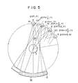
- first transfer timing "0” the CPU 34 produces projection data "0" at point P(m, n), as shown in Fig. 5.
- the CPU 34 produces the projection data "0" at second transfer timing "1”.
- third transfer timing "2” the CPU 34 then transfers projection data "1" at point P(m + 1, n) which is spaced apart by the angle A8 from the point P(m, n).
- the CPU 34 also transfers projection data "1" at fourth transfer timing "3".
- the interpolator 35 interpolates the projection data which are sequentially transferred thereto.
- the interpolator 35 interpolates two adjacent projection data which are sequentially transferred from the CPU 34 to obtain estimated interpolating data "0.5" at point P'(m + 1/2, n) shown in Fig. 5.
- Estimated interpolating data "1.5” at point P'(m + 3/2, n) and estimated interpolating data "2.5” at P'(m + 5/2, n) can be obtained in the same manner as described above.
- the estimated data and the actual projection data are supplied one after another to an image reconstructor 36.
- the image reconstructor 36 performs image reconstruction for each data supplied from the interpolator 35. Reconstructed image data obtained by the image reconstructor 36 are supplied to an image memory 37 and accumulated therein. Accumulated image data is then read out from the image memory 37 and is displayed at a CRT display 38.
- the projection data obtained by the first X-ray projection correspond to the number of channels (detector elements).
- positions P(m, n) and P(m + 1, n) (generally, two adjacent projection data are designated in the form of I(m, n) and I(m + 1, n)) as shown in Fig. 6, interpolating operation is performed for every channel of projection data I(m, n) and I(m + 1, n).
- I'(k, n) is interpolated data (for every channel) obtained by the projection data at two adjacent views of projections
- I(j, n) and I(j + 1, n) are projection data at two adjacent views of projections so as to obtain interpolated data I'(k, n).
- the interpolator 35 interpolates two adjacent projection data to obtain interpolated data.
- the interpolated data and the projection data are supplied one after another to the image reconstructor 36.
- the image reconstructor 36 performs image reconstruction for each data supplied from the interpolator 35.
- Fig. 7 is a block diagram showing the arrangement of the interpolator 35 of the CT apparatus according to an embodiment of the present invention.
- the interpolator 35 comprises: an input memory 35b for storing each projection data corresponding to one projection operation transferred from the CPU 34 in a memory area whose address is accessed by a first address counter 35a; a buffer memory 35d for reading out each projection data at a high speed and storing the projection data for each channel in a memory area whose address is accessed by a second address counter 35c; a multiplier 35e for multiplying the projection data read out from the buffer memory 35d for every channel beginning from Oth channel by 1/2; an interpolation memory 35f for sequentially storing the multiplied data therein and for reading out the multiplied data stored in a memory area whose address is accessed by the second address counter 35c; a resistor 35g for temporarily storing the data read out from the interpolation memory 35f; an adder 35h for adding the multiplied data from the multiplier 35e and the data read out from the register 35g; an output memory 35i for storing sum in a memory area whose address is accessed by the second address counter 35c and
- the CPU 34 transfers each projection data twice to the input memory 35b.
- the projection data transferred from the CPU 34 at the first transfer timing are stored in a memory area whose addresses are designated by the first address counter 35a.
- the input memory 35b transfers the projection data to the buffer memory 35d at a high speed.
- the buffer memory 35d thus stores the projection data transferred from the input memory 35b.
- the address for storing the projection data for each channel in the input memory 35b and the address for storing the projection data for each channel in the buffer memory 35d are respectively accessed by the first and second address counters 35a and 35c.
- the projection data for every channel are read out from the buffer memory 35d beginning from the Oth channel, and the multiplier 35e multiplies the readout data by 1/2.
- the multiplied result (multiplied data) is sequentially stored in a memory area of the interpolation memory 35f.
- the address of the memory area is accessed by the second address counter 35c.
- the data in the interpolating memory 35f is sequentially read out and supplied to the adder 35h.
- the above operation can be performed for the projection data for all the channels at the first transfer timing. While the projection data are .read out and multiplied and are supplied to the adder 35h, projection data for each channel at the second transfer timing are stored in the input memory 35b.
- the multiplied projection data at the first transfer timing cannot be added by the adder 35h to another data since the data stored in the register 35g is invalid. Therefore, the multiplied projection data at the first transfer timing cannot be used for reconstruction of the image.
- the projection data for all the channels at the first transfer timing are stored in the interpolation memory 35f
- the projection data for all the channels at the second transfer timing are transferred from the input memory 35b to the buffer memory 35d.
- the projection data for each channel beginning from the Oth channel are read out from the buffer memory 35d and are respectively multiplied by 1/2.
- the multiplied data are then supplied to the interpolation memory 35f and to the adder 35h.
- the multiplier 35e While the (k - l)th channel data among the projection data at the second transfer timing is multiplied by the multiplier 35e, the "k"th channel data among the projection data at the first transfer timing is transferred from the interpolation memory 35f to the register 35g.
- the "k"th multiplied channel data at the second transfer timing is properly stored in the interpolation memory 35f.
- the multiplied result or product of the "k"th channel data among the projection data at the second transfer timing is supplied from the multiplier 35e to the adder 35h, the multiplied result of the "k"th channel data among the projection data at the first transfer timing is supplied from the register 35g to the adder 35h.
- the multiplied result of the "k"th channel data at the second transfer timing is added to the multiplied result of the "k"th channel data at the first transfer timing.
- the sum thus obtained is stored as interpolated data in the output memory 35i.
- Interpolated data for each channel is obtained in this manner and is sequentially stored in the output memory 35i.
- the above operation is repeated for all the projection data transferred from the CPU 34 at the subsequent timings so as to obtain the reconstructed image.
- the CPU 34 and the interpolator 35 produce the estimated data, like a pipeline, and achieve the fast generation of estimated data.
- the image reconstructor 36 produces a fast reconstructed image.
- the word "estimated data” means both an actual projection data and an interpolated data. It is also valuable in the fourth generation CT apparatus comprising the stationary arc of fixed detectors to interpolate projection data by the interpolator of the invention.
- Fig. 8 shows an interpolator for performing such interpolation of a CT apparatus according to another embodiment of the present invention.
- the circuit arrangement shown in Fig. 8 is substantially the same as that shown in Fig. 7, except that the CPU 34 transfers data at a timing different from that used in the arrangement in Fig.
- the transfer sequence of the projection data from the CPU 34 is shown in the table of Fig. 9.
- the projection data at the first transfer timing is consecutively transferred twice.
- the projection data at the second and third transfer timings are respectively transferred once.
- the projection data at the fourth transfer timing is transferred twice; and the pieces of projection data at the fifth and sixth transfer timings are respectively transferred once.
- the above operation is repeated: generally, the "i"th projection data is transferred twice, and the (i + l)th projection data and the (i + 2) projection data are respectively transferred once, where "i" is a natural number.
- the projection data at the first transfer timing are stored in a memory area of the input memory 35b, whose address is accessed by the first address counter 35a.
- the projection data for all the channels at the first transfer timing are stored in the input memory 35b, the projection data are transferred to the buffer memory 35d at high speed and are stored in a memory area whose address is accessed by the address counter 35c.
- the projection data which are stored in the first buffer memory 35d are sequentially read out for each channel beginning from the Oth channel.
- the projection data for each channel is then supplied to the multiplier 35e and are multiplied by 1/4.
- the projection data for each channel is transferred and stored in the interpolation memory 35f.
- the multiplication result or product is supplied to the adder 35h and is added to the multiplication result from the multiplier 41. The sum is then supplied to the output memory 35i.
- the multiplied projection data at the first transfer timing are added, the product of the second multiplier 41 is invalid. Thus, the multiplied projection data are not used for image reconstruction. Thereafter, the projection data at the second transfer timing (the same as the projection data at the first transfer timing) from the CPU 34 are transferred to the input memory 35b and stored therein. After the projection data for all the channels at the second transfer timing are stored, they are transferred to the first buffer memory 35d at a high speed. Before the storage of the data at the second transfer timing, all the projection data for all the channels at the first transfer timing have been transferred to the interpolation memory 35f.
- the projection data at the second transfer timing are sequentially read out for each channel beginning from the "0"th channel in the same manner as in the projection data at the first transfer timing and are stored in the interpolation memory 35f. At the same time, they are supplied to the multiplier 35e and are respectively multiplied by one. It is noted that the "k"th channel projection data at the first transfer timing is transferred to the register 35g before the "k"th channel projection data at the second transfer timing is stored in the interpolation memory 35f.
- the multiplied result obtained by multiplying the "k"th channel projection data at the first transfer timing is supplied from the multiplier 41 to the adder 35h. Therefore, the multiplied result of the "k"th channel projection data at the second transfer timing and the multiplied result of the "k"th channel projection data at the first transfer timing are added by the adder 35h.
- This sum is stored in an output memory 35i.
- the sum data for each channel is sequentially stored in the output memory 35i.
- the data stored in the output memory 35i is read out therefrom and is supplied to the image reconstructor 36.
- the multipliers of the first and second multipliers 35e and 41 are determined to be different values in accordance with the corresponding transfer sequences.
- the multipliers at the first, second, third and fourth transfer timings are respectively set in the first multiplier 35e to be 1/4, 1/2, 3/4 and 2/4.
- the multipliers at the first, second, third and fourth transfer timings are respectively set in the second multiplier 41 to be 1/2, 1/4, 2/4 and 3/4.
- 400 pieces of estimated data are generated from 300 pieces of actual projection data.
- the precision of the reconstruction image can be improved in the same manner as in the first embodiment.
- any feature and arrangement of interpolation may be utilized only if each projection data is stored and is interpolated with the immediately following projection data.
- the projection data may be transferred from the CPU 34 to the input memory 35b once and the each data may be read out twice and is supplied to the multiplier 35e through the buffer memory 35d, instead of transferring each projection data twice.
- the interpolation speed can be further increased.
- the circuit arrangement can be simplified, thus simplifying monitoring of the software. Since a large-capacity memory for storing all the projection for one picture is not required, the structure of the apparatus may also be simplified. Further, since data retrieval and writing involving a large-capacity memory need not be performed, the processing speed can thus be increased. Further, since the CPU and the interpolator produce the estimated data, like a pipeline, the image can be reconstructed at a high speed.
Landscapes
- Physics & Mathematics (AREA)
- General Physics & Mathematics (AREA)
- Engineering & Computer Science (AREA)
- Theoretical Computer Science (AREA)
- Apparatus For Radiation Diagnosis (AREA)
- Analysing Materials By The Use Of Radiation (AREA)
Applications Claiming Priority (2)
| Application Number | Priority Date | Filing Date | Title |
|---|---|---|---|
| JP380/82 | 1982-01-06 | ||
| JP57000380A JPS58118735A (ja) | 1982-01-06 | 1982-01-06 | コンピユ−タ断層撮影装置 |
Publications (3)
| Publication Number | Publication Date |
|---|---|
| EP0083455A2 true EP0083455A2 (fr) | 1983-07-13 |
| EP0083455A3 EP0083455A3 (en) | 1983-09-14 |
| EP0083455B1 EP0083455B1 (fr) | 1987-04-01 |
Family
ID=11472186
Family Applications (1)
| Application Number | Title | Priority Date | Filing Date |
|---|---|---|---|
| EP82112119A Expired EP0083455B1 (fr) | 1982-01-06 | 1982-12-30 | Appareil de tomographie par calculateur et méthode pour reconstruire l'image en coupe d'un objet |
Country Status (4)
| Country | Link |
|---|---|
| US (1) | US4682289A (fr) |
| EP (1) | EP0083455B1 (fr) |
| JP (1) | JPS58118735A (fr) |
| DE (1) | DE3275953D1 (fr) |
Cited By (6)
| Publication number | Priority date | Publication date | Assignee | Title |
|---|---|---|---|---|
| EP0142417B1 (fr) * | 1983-10-25 | 1987-12-02 | Thomson-Cgr | Procédé d'acquisition et de reconstruction d'image par tomodensitomètrie, et tomodensitomètre mettant en oeuvre ce procédé |
| WO1988001888A1 (fr) * | 1986-09-13 | 1988-03-24 | Jin Kyung Kim | Installation informatisee de traitement medical avec fonction de depistage de la position de cellules malignes |
| EP0182186A3 (fr) * | 1984-11-13 | 1988-12-21 | General Electric Company | Appareil et méthode de reconstruction d'image par rétro-projection |
| EP0265334A3 (en) * | 1986-10-20 | 1989-10-25 | Elscint Ltd. | Binary space interpolation |
| WO1991002320A1 (fr) * | 1989-08-09 | 1991-02-21 | W.L. Systems, Inc. | Procede et appareil de calcul de balayages tomographiques |
| US5293312A (en) * | 1991-06-20 | 1994-03-08 | Waggener Robert G | Method and apparatus for computing tomographic scans |
Families Citing this family (11)
| Publication number | Priority date | Publication date | Assignee | Title |
|---|---|---|---|---|
| JPS59183737A (ja) * | 1983-04-05 | 1984-10-18 | 株式会社東芝 | 第4世代x線ct装置 |
| JPS6137139A (ja) * | 1984-07-27 | 1986-02-22 | 横河メディカルシステム株式会社 | Ct装置 |
| EP0333857B1 (fr) * | 1986-09-30 | 1993-04-07 | Yokogawa Medical Systems, Ltd | Tomographie computerisee a radiations |
| US5381295A (en) * | 1991-12-12 | 1995-01-10 | Datamax Electronics, Inc. | Resetable battery drain limitation circuit with improved latching relay |
| TW569088B (en) * | 2002-09-13 | 2004-01-01 | Htc Corp | Method of changing CPU frequency |
| JP2005328916A (ja) * | 2004-05-18 | 2005-12-02 | Hamamatsu Photonics Kk | 画像再構成方法 |
| JP4717511B2 (ja) * | 2005-05-20 | 2011-07-06 | ジーイー・メディカル・システムズ・グローバル・テクノロジー・カンパニー・エルエルシー | X線ct画像再構成方法およびx線ct装置 |
| US8938104B2 (en) * | 2008-08-29 | 2015-01-20 | Varian Medical Systems International Ag | Systems and methods for adaptive filtering |
| US9235907B2 (en) * | 2012-03-20 | 2016-01-12 | Juan C. Ramirez Giraldo | System and method for partial scan artifact reduction in myocardial CT perfusion |
| EP3766038A4 (fr) * | 2018-03-15 | 2021-12-15 | Redzone Robotics, Inc. | Techniques de traitement d'image pour inspection à capteurs multiples d'intérieurs de tuyaux |
| US11750007B2 (en) | 2020-08-06 | 2023-09-05 | Rev Ambulance Group Orlando, Inc. | System for preserving the charge of a motor vehicle battery |
Family Cites Families (20)
| Publication number | Priority date | Publication date | Assignee | Title |
|---|---|---|---|---|
| US3983398A (en) * | 1974-11-29 | 1976-09-28 | The Board Of Trustees Of Leland Stanford Junior University | Method and apparatus for X-ray or γ-ray 3-D tomography using a fan beam |
| DE2521171A1 (de) * | 1975-05-13 | 1976-11-25 | Philips Patentverwaltung | Anordnung zur ermittlung der verteilung der absorption oder der emission von strahlung in einer ebene eines koerpers |
| US4052620A (en) * | 1975-11-28 | 1977-10-04 | Picker Corporation | Method and apparatus for improved radiation detection in radiation scanning systems |
| DE2556012A1 (de) * | 1975-12-12 | 1977-06-16 | Philips Patentverwaltung | Verfahren und anordnung zur ermittlung der raeumlichen verteilung einer strahlung in einer ebene eines koerpers |
| GB1574823A (en) * | 1976-03-27 | 1980-09-10 | Emi Ltd | Video display arrangements |
| JPS586959B2 (ja) * | 1976-08-20 | 1983-02-07 | 日本電信電話株式会社 | 曲線発生器 |
| GB1594751A (en) * | 1977-01-31 | 1981-08-05 | Tokyo Shibaura Electric Co | Method and apparatus for tomography by means of penetrating radiation |
| DE2708604A1 (de) * | 1977-02-28 | 1978-08-31 | Siemens Ag | Schichtgeraet zur herstellung von transversalschichtbildern |
| JPS544585A (en) * | 1977-06-14 | 1979-01-13 | Toshiba Corp | Tomographic apparatus by radiations |
| US4135247A (en) * | 1977-08-15 | 1979-01-16 | Siemens Aktiengesellschaft | Tomography signal processing system |
| US4136388A (en) * | 1977-08-26 | 1979-01-23 | U.S. Philips Corporation | Data acquisition system for computed tomography |
| US4293912A (en) * | 1977-09-30 | 1981-10-06 | Technicare Corporation | Tomographic apparatus |
| DE2816462A1 (de) * | 1978-04-15 | 1979-10-25 | Philips Patentverwaltung | Verfahren zur erzeugung verbesserter rekonstruktionsbilder in computer-tomographiegeraeten |
| GB1602071A (en) * | 1978-05-12 | 1981-11-04 | Emi Ltd | Processing arrangements for medical examination |
| US4222104A (en) * | 1978-11-02 | 1980-09-09 | E M I Limited | Radiography |
| JPS5599240A (en) * | 1979-01-22 | 1980-07-29 | Tokyo Shibaura Electric Co | Ct scanner |
| US4280178A (en) * | 1979-08-24 | 1981-07-21 | General Electric Company | Computerized tomographic reconstruction method utilizing reflection |
| US4301473A (en) * | 1980-02-22 | 1981-11-17 | Atari, Inc. | Method and apparatus for video signal resolution enhancement |
| JPS56136529A (en) * | 1980-03-28 | 1981-10-24 | Tokyo Shibaura Electric Co | Apparatus for reconstituting image |
| US4386528A (en) * | 1981-08-07 | 1983-06-07 | General Electric Company | Method and means for generating pixel data in an ultrasonic scanning system |
-
1982
- 1982-01-06 JP JP57000380A patent/JPS58118735A/ja active Granted
- 1982-12-30 EP EP82112119A patent/EP0083455B1/fr not_active Expired
- 1982-12-30 DE DE8282112119T patent/DE3275953D1/de not_active Expired
-
1986
- 1986-01-23 US US06/821,211 patent/US4682289A/en not_active Expired - Fee Related
Cited By (8)
| Publication number | Priority date | Publication date | Assignee | Title |
|---|---|---|---|---|
| EP0142417B1 (fr) * | 1983-10-25 | 1987-12-02 | Thomson-Cgr | Procédé d'acquisition et de reconstruction d'image par tomodensitomètrie, et tomodensitomètre mettant en oeuvre ce procédé |
| EP0182186A3 (fr) * | 1984-11-13 | 1988-12-21 | General Electric Company | Appareil et méthode de reconstruction d'image par rétro-projection |
| WO1988001888A1 (fr) * | 1986-09-13 | 1988-03-24 | Jin Kyung Kim | Installation informatisee de traitement medical avec fonction de depistage de la position de cellules malignes |
| EP0265334A3 (en) * | 1986-10-20 | 1989-10-25 | Elscint Ltd. | Binary space interpolation |
| WO1991002320A1 (fr) * | 1989-08-09 | 1991-02-21 | W.L. Systems, Inc. | Procede et appareil de calcul de balayages tomographiques |
| US5307264A (en) * | 1989-08-09 | 1994-04-26 | W. L. Systems, Inc. | Method and apparatus for computing tomographic scans |
| AU649409B2 (en) * | 1989-08-09 | 1994-05-26 | W. L. Systems, Inc. | Method and apparatus for computing tomographic scans |
| US5293312A (en) * | 1991-06-20 | 1994-03-08 | Waggener Robert G | Method and apparatus for computing tomographic scans |
Also Published As
| Publication number | Publication date |
|---|---|
| JPH0116494B2 (fr) | 1989-03-24 |
| DE3275953D1 (en) | 1987-05-07 |
| EP0083455A3 (en) | 1983-09-14 |
| US4682289A (en) | 1987-07-21 |
| EP0083455B1 (fr) | 1987-04-01 |
| JPS58118735A (ja) | 1983-07-14 |
Similar Documents
| Publication | Publication Date | Title |
|---|---|---|
| US4682289A (en) | View interpolation in a tomography system using pipe line processing | |
| US6256370B1 (en) | Method and apparatus for performing tomosynthesis | |
| US4558462A (en) | Apparatus for correcting image distortions automatically by inter-image processing | |
| US5073911A (en) | Computerized tomographic apparatus | |
| US5552605A (en) | Motion correction based on reprojection data | |
| US6400789B1 (en) | On-line image reconstruction in helical CT scanners | |
| US4446521A (en) | Image reconstruction apparatus and process | |
| US4495645A (en) | Computed tomography device | |
| US4549265A (en) | Method of and device for image reconstruction in computed tomography | |
| US5414622A (en) | Method and apparatus for back projecting image data into an image matrix location | |
| US4598369A (en) | Tomography apparatus and method | |
| EP0182186A2 (fr) | Appareil et méthode de reconstruction d'image par rétro-projection | |
| US4144570A (en) | Method of and device for measuring the distribution of a radiation in a plane of a body | |
| US5420788A (en) | Method for processing data in 2D and 3D computed X-ray tomography | |
| JPS61209641A (ja) | X線ct装置 | |
| GB1593605A (en) | Method of and arrangement for determining the distribution of the absorption in a section of a body | |
| US5047931A (en) | Parallel computation of fan-beam back-projection reconstruction algorithm in computed tomography | |
| CN100581473C (zh) | 产生跳动的心脏的计算机断层造影图像的方法和设备 | |
| US4212062A (en) | Tomographic imaging system | |
| US4620153A (en) | Magnetic resonance imaging system | |
| US4654796A (en) | System for computing correction factors for sensitivity differences in detector channels of an X-ray tomography apparatus | |
| JP3913798B2 (ja) | 画像再構成処理装置 | |
| US6163617A (en) | Backprojection with a multi-color rendering engine | |
| JP3356454B2 (ja) | コンピュータ断層撮影装置 | |
| JPH067342A (ja) | X線コンピュータ断層像撮影装置 |
Legal Events
| Date | Code | Title | Description |
|---|---|---|---|
| PUAI | Public reference made under article 153(3) epc to a published international application that has entered the european phase |
Free format text: ORIGINAL CODE: 0009012 |
|
| PUAL | Search report despatched |
Free format text: ORIGINAL CODE: 0009013 |
|
| 17P | Request for examination filed |
Effective date: 19830127 |
|
| AK | Designated contracting states |
Designated state(s): DE FR GB NL |
|
| AK | Designated contracting states |
Designated state(s): DE FR GB NL |
|
| RAP1 | Party data changed (applicant data changed or rights of an application transferred) |
Owner name: KABUSHIKI KAISHA TOSHIBA |
|
| GRAA | (expected) grant |
Free format text: ORIGINAL CODE: 0009210 |
|
| AK | Designated contracting states |
Kind code of ref document: B1 Designated state(s): DE FR GB NL |
|
| ET | Fr: translation filed | ||
| REF | Corresponds to: |
Ref document number: 3275953 Country of ref document: DE Date of ref document: 19870507 |
|
| PLBE | No opposition filed within time limit |
Free format text: ORIGINAL CODE: 0009261 |
|
| STAA | Information on the status of an ep patent application or granted ep patent |
Free format text: STATUS: NO OPPOSITION FILED WITHIN TIME LIMIT |
|
| 26N | No opposition filed | ||
| PGFP | Annual fee paid to national office [announced via postgrant information from national office to epo] |
Ref country code: FR Payment date: 19961211 Year of fee payment: 15 |
|
| PGFP | Annual fee paid to national office [announced via postgrant information from national office to epo] |
Ref country code: GB Payment date: 19961223 Year of fee payment: 15 |
|
| PGFP | Annual fee paid to national office [announced via postgrant information from national office to epo] |
Ref country code: NL Payment date: 19961231 Year of fee payment: 15 |
|
| PGFP | Annual fee paid to national office [announced via postgrant information from national office to epo] |
Ref country code: DE Payment date: 19970107 Year of fee payment: 15 |
|
| PG25 | Lapsed in a contracting state [announced via postgrant information from national office to epo] |
Ref country code: GB Free format text: LAPSE BECAUSE OF NON-PAYMENT OF DUE FEES Effective date: 19971230 |
|
| PG25 | Lapsed in a contracting state [announced via postgrant information from national office to epo] |
Ref country code: FR Free format text: THE PATENT HAS BEEN ANNULLED BY A DECISION OF A NATIONAL AUTHORITY Effective date: 19971231 |
|
| PG25 | Lapsed in a contracting state [announced via postgrant information from national office to epo] |
Ref country code: NL Free format text: LAPSE BECAUSE OF NON-PAYMENT OF DUE FEES Effective date: 19980701 |
|
| GBPC | Gb: european patent ceased through non-payment of renewal fee |
Effective date: 19971230 |
|
| NLV4 | Nl: lapsed or anulled due to non-payment of the annual fee |
Effective date: 19980701 |
|
| PG25 | Lapsed in a contracting state [announced via postgrant information from national office to epo] |
Ref country code: DE Free format text: LAPSE BECAUSE OF NON-PAYMENT OF DUE FEES Effective date: 19980901 |
|
| REG | Reference to a national code |
Ref country code: FR Ref legal event code: ST |