EP0083896A1 - Kühlvorrichtung für die Abdeckplatten der Rotorschaufeln einer Turbine - Google Patents
Kühlvorrichtung für die Abdeckplatten der Rotorschaufeln einer Turbine Download PDFInfo
- Publication number
- EP0083896A1 EP0083896A1 EP82402404A EP82402404A EP0083896A1 EP 0083896 A1 EP0083896 A1 EP 0083896A1 EP 82402404 A EP82402404 A EP 82402404A EP 82402404 A EP82402404 A EP 82402404A EP 0083896 A1 EP0083896 A1 EP 0083896A1
- Authority
- EP
- European Patent Office
- Prior art keywords
- cooling
- blades
- heels
- turbine
- distributor
- Prior art date
- Legal status (The legal status is an assumption and is not a legal conclusion. Google has not performed a legal analysis and makes no representation as to the accuracy of the status listed.)
- Granted
Links
- 238000001816 cooling Methods 0.000 title claims abstract description 60
- 238000005070 sampling Methods 0.000 claims abstract description 3
- 230000002093 peripheral effect Effects 0.000 claims description 13
- 238000011144 upstream manufacturing Methods 0.000 claims description 12
- 238000007789 sealing Methods 0.000 claims description 6
- 210000003462 vein Anatomy 0.000 claims description 6
- 238000003801 milling Methods 0.000 claims description 5
- 238000006073 displacement reaction Methods 0.000 claims 1
- 239000007789 gas Substances 0.000 description 9
- 238000000034 method Methods 0.000 description 4
- 239000000243 solution Substances 0.000 description 4
- 239000002184 metal Substances 0.000 description 2
- 239000011248 coating agent Substances 0.000 description 1
- 238000000576 coating method Methods 0.000 description 1
- 238000004891 communication Methods 0.000 description 1
- 230000000295 complement effect Effects 0.000 description 1
- 239000000112 cooling gas Substances 0.000 description 1
- 239000012761 high-performance material Substances 0.000 description 1
- 238000002347 injection Methods 0.000 description 1
- 239000007924 injection Substances 0.000 description 1
- 238000009434 installation Methods 0.000 description 1
- 238000004519 manufacturing process Methods 0.000 description 1
- 239000000463 material Substances 0.000 description 1
- 230000000284 resting effect Effects 0.000 description 1
Images
Classifications
-
- F—MECHANICAL ENGINEERING; LIGHTING; HEATING; WEAPONS; BLASTING
- F01—MACHINES OR ENGINES IN GENERAL; ENGINE PLANTS IN GENERAL; STEAM ENGINES
- F01D—NON-POSITIVE DISPLACEMENT MACHINES OR ENGINES, e.g. STEAM TURBINES
- F01D5/00—Blades; Blade-carrying members; Heating, heat-insulating, cooling or antivibration means on the blades or the members
- F01D5/12—Blades
- F01D5/22—Blade-to-blade connections, e.g. for damping vibrations
- F01D5/225—Blade-to-blade connections, e.g. for damping vibrations by shrouding
-
- F—MECHANICAL ENGINEERING; LIGHTING; HEATING; WEAPONS; BLASTING
- F01—MACHINES OR ENGINES IN GENERAL; ENGINE PLANTS IN GENERAL; STEAM ENGINES
- F01D—NON-POSITIVE DISPLACEMENT MACHINES OR ENGINES, e.g. STEAM TURBINES
- F01D11/00—Preventing or minimising internal leakage of working-fluid, e.g. between stages
- F01D11/08—Preventing or minimising internal leakage of working-fluid, e.g. between stages for sealing space between rotor blade tips and stator
-
- F—MECHANICAL ENGINEERING; LIGHTING; HEATING; WEAPONS; BLASTING
- F01—MACHINES OR ENGINES IN GENERAL; ENGINE PLANTS IN GENERAL; STEAM ENGINES
- F01D—NON-POSITIVE DISPLACEMENT MACHINES OR ENGINES, e.g. STEAM TURBINES
- F01D11/00—Preventing or minimising internal leakage of working-fluid, e.g. between stages
- F01D11/08—Preventing or minimising internal leakage of working-fluid, e.g. between stages for sealing space between rotor blade tips and stator
- F01D11/10—Preventing or minimising internal leakage of working-fluid, e.g. between stages for sealing space between rotor blade tips and stator using sealing fluid, e.g. steam
-
- F—MECHANICAL ENGINEERING; LIGHTING; HEATING; WEAPONS; BLASTING
- F01—MACHINES OR ENGINES IN GENERAL; ENGINE PLANTS IN GENERAL; STEAM ENGINES
- F01D—NON-POSITIVE DISPLACEMENT MACHINES OR ENGINES, e.g. STEAM TURBINES
- F01D9/00—Stators
- F01D9/06—Fluid supply conduits to nozzles or the like
-
- F—MECHANICAL ENGINEERING; LIGHTING; HEATING; WEAPONS; BLASTING
- F05—INDEXING SCHEMES RELATING TO ENGINES OR PUMPS IN VARIOUS SUBCLASSES OF CLASSES F01-F04
- F05B—INDEXING SCHEME RELATING TO WIND, SPRING, WEIGHT, INERTIA OR LIKE MOTORS, TO MACHINES OR ENGINES FOR LIQUIDS COVERED BY SUBCLASSES F03B, F03D AND F03G
- F05B2240/00—Components
- F05B2240/80—Platforms for stationary or moving blades
- F05B2240/801—Platforms for stationary or moving blades cooled platforms
-
- F—MECHANICAL ENGINEERING; LIGHTING; HEATING; WEAPONS; BLASTING
- F05—INDEXING SCHEMES RELATING TO ENGINES OR PUMPS IN VARIOUS SUBCLASSES OF CLASSES F01-F04
- F05D—INDEXING SCHEME FOR ASPECTS RELATING TO NON-POSITIVE-DISPLACEMENT MACHINES OR ENGINES, GAS-TURBINES OR JET-PROPULSION PLANTS
- F05D2240/00—Components
- F05D2240/80—Platforms for stationary or moving blades
- F05D2240/81—Cooled platforms
Definitions
- the present invention relates to a device for cooling the heels of moving blades of a turbomachine turbine.
- the constant research related to the improvement of turbomachines aims in particular to increase the performances obtained while respecting the multiple constraints imposed as much by the possibilities of industrial implementation as by the conditions of exploitation of the materials.
- the pursuit of these objectives leads to taking into account two conditions: on the one hand, increasing the operating temperatures and on the other hand, reducing or avoiding the losses affecting the main circulation flow gases.
- U.S. Patent 3,034,298 describes a turbine cooling system.
- the cooling air from a manifold 76 is directed by holes 168, on the one hand, in the distributor blades 65 and on the other hand, on the turbine ring 102 that the air passes through to be discharged radially into the main vein.
- a additional cooling circuit is provided for the radially internal parts.
- French patent 1,548,541 relates to a method and devices for cooling gas turbines.
- the system described associates the cooling of a wheel disc with the supply by a tube of an internal cavity from which the cooling air is directed on the region of the foot of the blades or on a hoop or rim surrounding the blade heads.
- Patent of the United Kingdom of Great Britain 1,519,449 relates to a turbomachine in which air for cooling the turbine is supplied to chambers formed in the turbine ring. This air is introduced into the main gas stream by passages through a complementary blade directing this air in the direction of the flow obtained at the outlet of the main distributor. The exit of this air into the vein retains a centripetal radial component.
- the object of the present invention is therefore to define a device for cooling the peripheral heels of movable blades of a turbine in which, according to techniques known from the prior art, an external enclosure supplied with air provides the air cooling to the fixed blades of a distributor, located upstream of the movable blades, passing through a capacity formed at the head of said blades and to a turbine ring constituting the fixed part opposite the turbine rotor.
- This device according to the invention is characterized in that passages are also provided from said enclosure for directing air on the peripheral heels of the movable blades of the turbine rotor so as to cool said heel blades. from their leading edge located on the upstream side with respect to the direction of gas circulation in the main gas stream.
- said cooling air passages can be formed by multiple holes machined in the heels of the fixed distributor vanes on the downstream side according to a multi-hole arrangement.
- a film cooling remarkable for its efficiency for said heels of moving blades is thus obtained.
- a constant ejection section is obtained.
- the choice of the arrangement and the diameter of these holes makes it possible to obtain an accurate calibration of the cooling air flow.
- said cooling air passages are made through an axial annular space formed between two parts of a downstream flange of the distributor and opening at its radially internal end by a multitude of millings made in the end of the downstream part of said flange creating orifices between said flange and an associated connecting square.
- film cooling is also obtained from multi-holes having the same advantages of efficiency and precise calibration of the air flow with a constant ejection section.
- the device according to the invention is advantageously supplemented by the installation of associated means ensuring the seal between the external enclosure from which the cooling air is taken and the main gas flow stream.
- Said sealing means in a first advantageous embodiment, consist of a seal formed of elastic blades in sectors, one end of which is fixed to the downstream flange of the distributor and the other end of which bears on the ring of turbine.
- This flexible seal makes it possible to absorb dimensional differences of various origins, manufacturing tolerances, deformations, differential thermal expansions, between the distributor and the turbine ring.
- any risk of interference between distributor and ring is avoided and likewise, this solution does not affect the dismantling of the turbine modules.
- the seal is constituted by elastic tabs, one end of which is fixed to a radially external part of the downstream flange of the distributor. These tabs, at the other end, are welded to an annular flange which is supported on a front surface of the turbine ring and on an axial surface of the downstream part of the distributor blade platform.
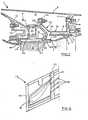
- FIG. 1 is shown in axial section a portion of a turbomachine and more specifically a portion of high pressure turbine 1 in a first embodiment of the invention.
- This turbine 1 is limited by an outer casing 2 carrying a radial flange 3 to which is bolted a support 4 which carries a turbine ring 5 delimiting the external contour of circulation of the main gas stream.
- a perforated annular sheet 6 provides outside the turbine ring 5 a cooling chamber 7.
- the turbine ring 5 is internally lined with a sealing and wear coating 8 corresponding to the heel 9 of the blades mobiles 10 of a first turbine rotor stage.
- a casing 11 for dispenser support Inside the turbine casing 2, there is also fixed to said casing by a connection not shown in the drawing, a casing 11 for dispenser support.
- An upstream intermediate support 12 linked to a flange 13 of the casing 11 and a downstream flange 14 of the casing 11 carry the distributor stage, the platforms 15 of fixed vanes 16 of which are linked to them on each side.
- An outer enclosure 17 is formed between the outer casing 2 of the turbine, on the one hand, and, on the other hand, the turbine ring 5 and the distributor casing 11.
- a closure plate 18 resting on the upstream part 19 and on the downstream part 20 of the platform 15 of the distributor vanes 16 provides a capacity 21 at the top of the distributor vanes 16.
- the distributor housing 11, on the one hand, and the closure plate 18, on the other hand, have openings respectively 22 and 23 in which, via cylindrical sleeves, respectively 24 and 25 are mounted coils 26 which put the external enclosure 17 and the capacity 21 formed at the head of the distributor vanes 16 into communication.
- These coils 26 have at each end, respectively 27 and 28, a ball-shaped shape adapted to the cylindrical bore of the connecting sleeves, respectively 24 and 25.
- the edge 30 of the heel 9 has, with respect to the extension of the heel itself, a slightly raised profile whose interest will appear later in the description of the operation.
- the holes 29 of the platforms 15 of the distributor blades 16 are oblique holes, circumferentially inclined, at an a priori angle different from that of the trailing edge 31 of the distributor blades 16 and whose the optimal value is determined from criteria arising from the operation of the device as will be described later.
- a seal 32 Between the downstream flange 14 of the distributor housing 11 and the annular plate 6 of the turbine ring 5 is placed a seal 32.
- This seal 32 consists of elastic strips 33 in sectors, for example twelve in number.
- One end 34 of the blades 33 is bolted to the downstream flange 14 of the distributor housing 11 and the other end 35 of the blades 33 is in elastic support on the annular sheet metal 6 of the turbine ring 5.
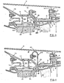
- FIG. 3 is shown, in a view similar to that of FIG. 1 and in a second embodiment of the invention, a part of a turbomachine in axial section and more precisely a part of a high-pressure turbine.
- the downstream flange 14 of the distributor housing 11 is made up of two annular parts, an upstream part 14a and a downstream part 14b.
- An area annular 36 is formed between these two parts 14a and 14b.
- the connection between the platforms 15 of the distributor vanes 16 and the flange 14 is made by means of a bracket 37.
- the upstream flange part 14a is fixed to the branch 37a of the bracket 37 in the radial position and the radially internal end 38 of the downstream flange portion 14b is supported on the branch 37b of the bracket 37 in the axial position.
- the radially internal face 38a of the end 38 of the downstream flange portion 14b bearing on the branch 37b of the bracket 37 comprises a series of longitudinal millings 39 starting from the radially internal end of the annular space 36 and opening out in line with the leading edge 30 of the heel 9 of the movable blades 10. Similarly to the first embodiment and for the same purpose, these millings 39 have a circumferential inclination.
- FIG 4 there is shown a variant according to the invention for the seal 32 placed between the turbine ring 5 and the flange 14 of the turbine distributor support casing.
- This seal 32 consists of elastic legs 40 in the shape of a butt which are for example twelve in number.
- One end 41 of the legs 40 is bolted to the downstream flange 14 of the distributor housing.
- the other end 42 is welded to an annular flange 42a which is, on the one hand, in front support on a radial upstream bearing 43 of the turbine ring 5 and, on the other hand, in radial support on an axial bearing 44 of the downstream part 20 of the platform 15 of the distributor vane 16.
- the cooling of the heels of movable blades obtained by the device according to the invention which has just been described is combined with an overall solution for cooling the hot parts of a turbine combined with obtaining minimum operating clearances between fixed parts and moving parts taking into account the repercussions of expansions in particular of thermal origin.
- the external turbine enclosure 17 is supplied with cooling air by any known means and according to any method adapted to the configuration and to the particular operating conditions of the turbomachine considered. These means have not been shown in the drawings and will not, like the process, be described in more detail.
- the cooling air through the multi-perforations of the annular sheet metal 6 cools in the form of impacts the turbine ring 5, the air jets passing through the cooling chamber 7.
- the cooling air, from the enclosure 17 and through the swiveling coils 26 also feeds the capacity 21 at the head of the distributor blades 16.
- a fraction of the air, from said capacity 21, is used for cooling the distributor blades 16 in which the air circulates in suitable channels.
- Another fraction of the air escapes from the capacity 21 through the holes 29 in the downstream part 20 of the platform 15 of the distributor blades 16.
- the air inlets passing through the multi-hole system thus formed create a film on the leading edge 30 of the heels 9 of movable blades 10 of the turbine.
- the calibration of the holes 29 allows precise control of the cooling air flow intended for the heels 9 of the movable blades lO and the optimal value given to the circumferential angle of inclination of these holes 29 allows the best cooling efficiency to be obtained. blade heels.
- This value is also chosen so as to avoid any disturbance created by the air jets in the vein.
- the raised profile given to the leading edge 30 of the blade heel 9 contributes to the efficiency of the cooling obtained.
- a constant ejection section of the cooling air is also obtained by this means according to the invention.
- the cooling blade heels obtained has a particularly advantageous application for high-performance materials, such as certain turbojets, in which the rotor blades used are of the cavity type and moreover have their own cooling mode, for example, with emission on the blade. In these applications, it is also important to ensure the best seal between the enclosure 17 for sampling the cooling air and the main gas flow stream. This is what makes it possible to obtain the seal 32 according to the invention.
- this seal 32 the mounting is made possible in addition without the risk of interference between the turbine ring 5 and the distributor housing 11, and the dismantling of the turbine modules is not affected.
- the flexibility of the gasket 32 makes it possible to absorb the dimensional differences which may appear between the turbine ring 5 and the distributor casing 11 and makes it possible to avoid introducing harmful play or causing mechanical stress on rooms.
- the cooling air from the external turbine enclosure 17, enters the annular space 36 formed between the upstream 14a and downstream 14b parts of the downstream flange of the distributor housing 11. Then the air escapes through the millings 39 located at the radially internal end, and these air inlets create a film on the leading edge 30 of the heels 9 of moving blades 10 of the turbine.
- the other operating conditions are similar to those which have been described for the first embodiment and similar advantageous results are also obtained.
Landscapes
- Engineering & Computer Science (AREA)
- Mechanical Engineering (AREA)
- General Engineering & Computer Science (AREA)
- Turbine Rotor Nozzle Sealing (AREA)
Applications Claiming Priority (2)
| Application Number | Priority Date | Filing Date | Title |
|---|---|---|---|
| FR8200121 | 1982-01-07 | ||
| FR8200121A FR2519374B1 (fr) | 1982-01-07 | 1982-01-07 | Dispositif de refroidissement des talons d'aubes mobiles d'une turbine |
Publications (2)
| Publication Number | Publication Date |
|---|---|
| EP0083896A1 true EP0083896A1 (de) | 1983-07-20 |
| EP0083896B1 EP0083896B1 (de) | 1986-02-26 |
Family
ID=9269753
Family Applications (1)
| Application Number | Title | Priority Date | Filing Date |
|---|---|---|---|
| EP82402404A Expired EP0083896B1 (de) | 1982-01-07 | 1982-12-31 | Kühlvorrichtung für die Abdeckplatten der Rotorschaufeln einer Turbine |
Country Status (5)
| Country | Link |
|---|---|
| US (1) | US4522557A (de) |
| EP (1) | EP0083896B1 (de) |
| JP (1) | JPS58128401A (de) |
| DE (1) | DE3269538D1 (de) |
| FR (1) | FR2519374B1 (de) |
Cited By (5)
| Publication number | Priority date | Publication date | Assignee | Title |
|---|---|---|---|---|
| FR2577280A1 (fr) * | 1985-02-12 | 1986-08-14 | Rolls Royce | Moteur a turbine a gaz |
| FR2752879A1 (fr) * | 1993-11-22 | 1998-03-06 | United Technologies Corp | Joints annulaires a air pour moteur a turbine a gaz |
| FR2903151A1 (fr) * | 2006-06-29 | 2008-01-04 | Snecma Sa | Dispositif de ventilation d'un carter d'echappement dans une turbomachine |
| FR2913050A1 (fr) * | 2007-02-28 | 2008-08-29 | Snecma Sa | Turbine haute-pression d'une turbomachine |
| WO2008092845A3 (en) * | 2007-01-31 | 2008-10-16 | Siemens Ag | A gas turbine |
Families Citing this family (44)
| Publication number | Priority date | Publication date | Assignee | Title |
|---|---|---|---|---|
| US4909706A (en) * | 1987-01-28 | 1990-03-20 | Union Carbide Corporation | Controlled clearance labyrinth seal |
| US4825640A (en) * | 1987-06-22 | 1989-05-02 | Sundstrand Corporation | Combustor with enhanced turbine nozzle cooling |
| US5134844A (en) * | 1990-07-30 | 1992-08-04 | General Electric Company | Aft entry cooling system and method for an aircraft engine |
| US5181826A (en) * | 1990-11-23 | 1993-01-26 | General Electric Company | Attenuating shroud support |
| US5224818A (en) * | 1991-11-01 | 1993-07-06 | General Electric Company | Air transfer bushing |
| US5252026A (en) * | 1993-01-12 | 1993-10-12 | General Electric Company | Gas turbine engine nozzle |
| US5993150A (en) * | 1998-01-16 | 1999-11-30 | General Electric Company | Dual cooled shroud |
| SE512085C2 (sv) * | 1998-05-28 | 2000-01-24 | Abb Ab | Rotormaskininrättning |
| WO2000053897A1 (en) * | 1999-03-11 | 2000-09-14 | Alm Development, Inc. | Gas turbine engine |
| KR100694370B1 (ko) * | 1999-05-14 | 2007-03-12 | 제너럴 일렉트릭 캄파니 | 터빈 노즐의 내측 및 외측 밴드에서 온도 부정합을 제어하는 장치 및 내측 또는 외측 밴드의 벽과 커버 사이의 온도 차이를 감소시키는 방법 |
| US6254345B1 (en) * | 1999-09-07 | 2001-07-03 | General Electric Company | Internally cooled blade tip shroud |
| US6363708B1 (en) | 1999-10-12 | 2002-04-02 | Alm Development, Inc. | Gas turbine engine |
| US6397576B1 (en) | 1999-10-12 | 2002-06-04 | Alm Development, Inc. | Gas turbine engine with exhaust compressor having outlet tap control |
| US6460324B1 (en) | 1999-10-12 | 2002-10-08 | Alm Development, Inc. | Gas turbine engine |
| US6382906B1 (en) * | 2000-06-16 | 2002-05-07 | General Electric Company | Floating spoolie cup impingement baffle |
| US6442945B1 (en) | 2000-08-04 | 2002-09-03 | Alm Development, Inc. | Gas turbine engine |
| AU2002366846A1 (en) * | 2001-12-13 | 2003-07-09 | Alstom Technology Ltd | Hot gas path subassembly of a gas turbine |
| FR2862338B1 (fr) * | 2003-11-17 | 2007-07-20 | Snecma Moteurs | Dispositif de liaison entre un distributeur et une enceinte d'alimentation pour injecteurs de fluide de refroidissement dans une turbomachine |
| EP1657407B1 (de) * | 2004-11-15 | 2011-12-28 | Rolls-Royce Deutschland Ltd & Co KG | Verfahren zur Kühlung der äusseren Deckbänder der Rotorschaufeln einer Gasturbine |
| US7246989B2 (en) * | 2004-12-10 | 2007-07-24 | Pratt & Whitney Canada Corp. | Shroud leading edge cooling |
| US7452184B2 (en) * | 2004-12-13 | 2008-11-18 | Pratt & Whitney Canada Corp. | Airfoil platform impingement cooling |
| US7226277B2 (en) * | 2004-12-22 | 2007-06-05 | Pratt & Whitney Canada Corp. | Pump and method |
| EP1746254B1 (de) * | 2005-07-19 | 2016-03-23 | Pratt & Whitney Canada Corp. | Vorrichtung sowie Verfahren zur Kühlung eines Turbinen-Mantelringsegments bzw. eines Deckbands einer Turbinenleitschaufel |
| US7771160B2 (en) * | 2006-08-10 | 2010-08-10 | United Technologies Corporation | Ceramic shroud assembly |
| US7665960B2 (en) | 2006-08-10 | 2010-02-23 | United Technologies Corporation | Turbine shroud thermal distortion control |
| US7611324B2 (en) * | 2006-11-30 | 2009-11-03 | General Electric Company | Method and system to facilitate enhanced local cooling of turbine engines |
| US7785067B2 (en) * | 2006-11-30 | 2010-08-31 | General Electric Company | Method and system to facilitate cooling turbine engines |
| US7690885B2 (en) * | 2006-11-30 | 2010-04-06 | General Electric Company | Methods and system for shielding cooling air to facilitate cooling integral turbine nozzle and shroud assemblies |
| FR2913051B1 (fr) * | 2007-02-28 | 2011-06-10 | Snecma | Etage de turbine dans une turbomachine |
| US8167546B2 (en) * | 2009-09-01 | 2012-05-01 | United Technologies Corporation | Ceramic turbine shroud support |
| US8689562B2 (en) | 2009-09-13 | 2014-04-08 | Donald W. Kendrick | Combustion cavity layouts for fuel staging in trapped vortex combustors |
| FR2953252B1 (fr) * | 2009-11-30 | 2012-11-02 | Snecma | Secteur de distributeur pour une turbomachine |
| RU2547541C2 (ru) * | 2010-11-29 | 2015-04-10 | Альстом Текнолоджи Лтд | Осевая газовая турбина |
| RU2547351C2 (ru) * | 2010-11-29 | 2015-04-10 | Альстом Текнолоджи Лтд | Осевая газовая турбина |
| RU2543101C2 (ru) * | 2010-11-29 | 2015-02-27 | Альстом Текнолоджи Лтд | Осевая газовая турбина |
| US9249732B2 (en) * | 2012-09-28 | 2016-02-02 | United Technologies Corporation | Panel support hanger for a turbine engine |
| WO2014163673A2 (en) | 2013-03-11 | 2014-10-09 | Bronwyn Power | Gas turbine engine flow path geometry |
| GB201308604D0 (en) * | 2013-05-14 | 2013-06-19 | Rolls Royce Plc | A shroud arrangement for a gas turbine engine |
| US10408071B2 (en) | 2013-09-18 | 2019-09-10 | United Technologies Corporation | BOAS thermal protection |
| DE102016115610A1 (de) | 2016-08-23 | 2018-03-01 | Rolls-Royce Deutschland Ltd & Co Kg | Gasturbine und Verfahren zum Aufhängen eines Turbinen-Leitschaufelsegments einer Gasturbine |
| GB201712025D0 (en) * | 2017-07-26 | 2017-09-06 | Rolls Royce Plc | Gas turbine engine |
| JP7267164B2 (ja) * | 2019-09-30 | 2023-05-01 | 不二サッシ株式会社 | 障子及び障子の組付構造 |
| US11415020B2 (en) | 2019-12-04 | 2022-08-16 | Raytheon Technologies Corporation | Gas turbine engine flowpath component including vectored cooling flow holes |
| FR3151878B1 (fr) * | 2023-08-02 | 2025-08-01 | Safran Aircraft Engines | Secteur d’un anneau pour une turbine d’une turbomachine d’aeronef |
Citations (10)
| Publication number | Priority date | Publication date | Assignee | Title |
|---|---|---|---|---|
| US3314648A (en) * | 1961-12-19 | 1967-04-18 | Gen Electric | Stator vane assembly |
| US3730640A (en) * | 1971-06-28 | 1973-05-01 | United Aircraft Corp | Seal ring for gas turbine |
| FR2216443A1 (de) * | 1973-02-05 | 1974-08-30 | Avco Corp | |
| GB1381277A (en) * | 1971-08-26 | 1975-01-22 | Rolls Royce | Sealing clearance control apparatus for gas turbine engines |
| GB1519449A (en) * | 1975-11-10 | 1978-07-26 | Rolls Royce | Gas turbine engine |
| GB1524956A (en) * | 1975-10-30 | 1978-09-13 | Rolls Royce | Gas tubine engine |
| FR2384949A1 (fr) * | 1977-03-26 | 1978-10-20 | Rolls Royce | Dispositif d'etancheite pour rotor de turbine a gaz |
| FR2450344A1 (fr) * | 1979-02-28 | 1980-09-26 | Mtu Muenchen Gmbh | Dispositif pour reduire au minimum et maintenir constants les jeux a la crete des aubes existants dans les turbines axiales, notamment pour turbomachines a gaz |
| US4280792A (en) * | 1979-02-09 | 1981-07-28 | Avco Corporation | Air-cooled turbine rotor shroud with restraints |
| US4311431A (en) * | 1978-11-08 | 1982-01-19 | Teledyne Industries, Inc. | Turbine engine with shroud cooling means |
Family Cites Families (7)
| Publication number | Priority date | Publication date | Assignee | Title |
|---|---|---|---|---|
| US3034298A (en) * | 1958-06-12 | 1962-05-15 | Gen Motors Corp | Turbine cooling system |
| FR1548541A (de) * | 1967-10-24 | 1968-12-06 | ||
| FR2030895A5 (de) * | 1969-05-23 | 1970-11-13 | Motoren Turbinen Union | |
| JPS4826086A (de) * | 1971-08-04 | 1973-04-05 | ||
| FR2280791A1 (fr) * | 1974-07-31 | 1976-02-27 | Snecma | Perfectionnements au reglage du jeu entre les aubes et le stator d'une turbine |
| US4157232A (en) * | 1977-10-31 | 1979-06-05 | General Electric Company | Turbine shroud support |
| DE2907749C2 (de) * | 1979-02-28 | 1985-04-25 | MTU Motoren- und Turbinen-Union München GmbH, 8000 München | Einrichtung zur Minimierung von Konstanthaltung des bei Axialturbinen von Gasturbinentriebwerken vorhandenen Schaufelspitzenspiels |
-
1982
- 1982-01-07 FR FR8200121A patent/FR2519374B1/fr not_active Expired
- 1982-12-31 EP EP82402404A patent/EP0083896B1/de not_active Expired
- 1982-12-31 DE DE8282402404T patent/DE3269538D1/de not_active Expired
-
1983
- 1983-01-05 US US06/455,732 patent/US4522557A/en not_active Expired - Lifetime
- 1983-01-06 JP JP58000755A patent/JPS58128401A/ja active Granted
Patent Citations (10)
| Publication number | Priority date | Publication date | Assignee | Title |
|---|---|---|---|---|
| US3314648A (en) * | 1961-12-19 | 1967-04-18 | Gen Electric | Stator vane assembly |
| US3730640A (en) * | 1971-06-28 | 1973-05-01 | United Aircraft Corp | Seal ring for gas turbine |
| GB1381277A (en) * | 1971-08-26 | 1975-01-22 | Rolls Royce | Sealing clearance control apparatus for gas turbine engines |
| FR2216443A1 (de) * | 1973-02-05 | 1974-08-30 | Avco Corp | |
| GB1524956A (en) * | 1975-10-30 | 1978-09-13 | Rolls Royce | Gas tubine engine |
| GB1519449A (en) * | 1975-11-10 | 1978-07-26 | Rolls Royce | Gas turbine engine |
| FR2384949A1 (fr) * | 1977-03-26 | 1978-10-20 | Rolls Royce | Dispositif d'etancheite pour rotor de turbine a gaz |
| US4311431A (en) * | 1978-11-08 | 1982-01-19 | Teledyne Industries, Inc. | Turbine engine with shroud cooling means |
| US4280792A (en) * | 1979-02-09 | 1981-07-28 | Avco Corporation | Air-cooled turbine rotor shroud with restraints |
| FR2450344A1 (fr) * | 1979-02-28 | 1980-09-26 | Mtu Muenchen Gmbh | Dispositif pour reduire au minimum et maintenir constants les jeux a la crete des aubes existants dans les turbines axiales, notamment pour turbomachines a gaz |
Cited By (8)
| Publication number | Priority date | Publication date | Assignee | Title |
|---|---|---|---|---|
| FR2577280A1 (fr) * | 1985-02-12 | 1986-08-14 | Rolls Royce | Moteur a turbine a gaz |
| FR2752879A1 (fr) * | 1993-11-22 | 1998-03-06 | United Technologies Corp | Joints annulaires a air pour moteur a turbine a gaz |
| FR2903151A1 (fr) * | 2006-06-29 | 2008-01-04 | Snecma Sa | Dispositif de ventilation d'un carter d'echappement dans une turbomachine |
| WO2008092845A3 (en) * | 2007-01-31 | 2008-10-16 | Siemens Ag | A gas turbine |
| US8267641B2 (en) | 2007-01-31 | 2012-09-18 | Siemens Aktiengesellschaft | Gas turbine |
| FR2913050A1 (fr) * | 2007-02-28 | 2008-08-29 | Snecma Sa | Turbine haute-pression d'une turbomachine |
| EP1965027A2 (de) | 2007-02-28 | 2008-09-03 | Societe Nationale D'etude Et De Construction De Moteurs D'aviation "Snecma" | Hochdruckturbine eines Turbinentriebwerks |
| EP1965027A3 (de) * | 2007-02-28 | 2011-01-26 | Snecma | Hochdruckturbine eines Turbinentriebwerks |
Also Published As
| Publication number | Publication date |
|---|---|
| FR2519374B1 (fr) | 1986-01-24 |
| FR2519374A1 (fr) | 1983-07-08 |
| DE3269538D1 (en) | 1986-04-03 |
| JPS58128401A (ja) | 1983-08-01 |
| JPH0115683B2 (de) | 1989-03-20 |
| EP0083896B1 (de) | 1986-02-26 |
| US4522557A (en) | 1985-06-11 |
Similar Documents
| Publication | Publication Date | Title |
|---|---|---|
| EP0083896A1 (de) | Kühlvorrichtung für die Abdeckplatten der Rotorschaufeln einer Turbine | |
| EP1972756B1 (de) | Interturbinen-Gehäuse mit Kühlkreislauf und dieses umfassendes Turbostrahltriebwerk | |
| EP0176447B1 (de) | Vorrichtung für die automatische Regelung des Spiels einer Labyrinthdichtung einer Turbomaschine | |
| EP2053200A1 (de) | Regelung des Blattspitzenspiels der Hochdruckturbine eines Turbinentriebwerks | |
| FR2582051A1 (fr) | Appareil de regulation de jeu pour machine a aubes a ecoulement de fluide | |
| EP4305280A1 (de) | Turbinenstatoranordnung | |
| EP3880939A1 (de) | Abdichtung zwischen einer rotorscheibe und einem stator einer turbomaschine | |
| FR2550275A1 (de) | ||
| FR3114839A1 (fr) | Aube de turbine pour turbomachine d’aéronef, comprenant une plateforme pourvue d’un canal de réjection de flux primaire en aval de la plateforme | |
| FR2652858A1 (fr) | Stator de turbomachine associe a des moyens de deformation. | |
| FR2931515A1 (fr) | Turbomachine avec diffuseur | |
| WO2022069845A1 (fr) | Aube de turbine pour turbomachine d'aéronef, comprenant une plateforme pourvue d'un canal de réjection de flux primaire vers une cavité de purge | |
| FR3109795A1 (fr) | Carter intermediaire de redressement avec bras structural monobloc | |
| FR3064050A1 (fr) | Chambre de combustion d'une turbomachine | |
| EP4314491A1 (de) | Vorrichtung zum abdichten und rückspritzen eines nebenstroms für eine turbinendüse | |
| EP4259906A1 (de) | Turbinenstatoranordnung mit einem radialen freiheitsgrad zwischen einer leitschaufelanordnung und einem dichtungsring | |
| FR3109406A1 (fr) | Dispositif de refroidissement d’un carter de turbine | |
| FR3101665A1 (fr) | Distributeur de turbine à aubage en composite à matrice céramique traversé par un circuit de ventilation métallique | |
| FR3160725A1 (fr) | Ensemble statorique de turbine de turbomachine d’aeronef, presentant un flux d’air de purge statorique a efficacite renforcee | |
| FR3115562A1 (fr) | Injecteur d’air de refroidissement pour turbine de turbomachine | |
| FR3152831A1 (fr) | Aubage de turbomachine | |
| FR3146934A1 (fr) | Ensemble d’étanchéité pour turbomachine | |
| EP4298320A1 (de) | Turbomaschinenverteiler mit einem gaswiedereinlasskanal mit einer tangentialen komponente | |
| WO2024194568A1 (fr) | Architecture pour joint d'etancheite de turbomachine | |
| EP4709971A1 (de) | Dichtung für eine turbomaschine |
Legal Events
| Date | Code | Title | Description |
|---|---|---|---|
| PUAI | Public reference made under article 153(3) epc to a published international application that has entered the european phase |
Free format text: ORIGINAL CODE: 0009012 |
|
| 17P | Request for examination filed |
Effective date: 19830108 |
|
| AK | Designated contracting states |
Designated state(s): DE FR GB |
|
| GRAA | (expected) grant |
Free format text: ORIGINAL CODE: 0009210 |
|
| AK | Designated contracting states |
Designated state(s): DE FR GB |
|
| REF | Corresponds to: |
Ref document number: 3269538 Country of ref document: DE Date of ref document: 19860403 |
|
| PLBE | No opposition filed within time limit |
Free format text: ORIGINAL CODE: 0009261 |
|
| STAA | Information on the status of an ep patent application or granted ep patent |
Free format text: STATUS: NO OPPOSITION FILED WITHIN TIME LIMIT |
|
| 26N | No opposition filed | ||
| REG | Reference to a national code |
Ref country code: FR Ref legal event code: CL |
|
| PGFP | Annual fee paid to national office [announced via postgrant information from national office to epo] |
Ref country code: FR Payment date: 20001117 Year of fee payment: 19 |
|
| PGFP | Annual fee paid to national office [announced via postgrant information from national office to epo] |
Ref country code: GB Payment date: 20001227 Year of fee payment: 19 |
|
| PGFP | Annual fee paid to national office [announced via postgrant information from national office to epo] |
Ref country code: DE Payment date: 20010226 Year of fee payment: 19 |
|
| PG25 | Lapsed in a contracting state [announced via postgrant information from national office to epo] |
Ref country code: GB Free format text: LAPSE BECAUSE OF NON-PAYMENT OF DUE FEES Effective date: 20011231 |
|
| REG | Reference to a national code |
Ref country code: GB Ref legal event code: IF02 |
|
| REG | Reference to a national code |
Ref country code: FR Ref legal event code: TP Ref country code: FR Ref legal event code: CD |
|
| PG25 | Lapsed in a contracting state [announced via postgrant information from national office to epo] |
Ref country code: DE Free format text: LAPSE BECAUSE OF NON-PAYMENT OF DUE FEES Effective date: 20020702 |
|
| GBPC | Gb: european patent ceased through non-payment of renewal fee |
Effective date: 20011231 |
|
| PG25 | Lapsed in a contracting state [announced via postgrant information from national office to epo] |
Ref country code: FR Free format text: LAPSE BECAUSE OF NON-PAYMENT OF DUE FEES Effective date: 20020830 |
|
| REG | Reference to a national code |
Ref country code: FR Ref legal event code: ST |