EP1965027A2 - Hochdruckturbine eines Turbinentriebwerks - Google Patents
Hochdruckturbine eines Turbinentriebwerks Download PDFInfo
- Publication number
- EP1965027A2 EP1965027A2 EP08151865A EP08151865A EP1965027A2 EP 1965027 A2 EP1965027 A2 EP 1965027A2 EP 08151865 A EP08151865 A EP 08151865A EP 08151865 A EP08151865 A EP 08151865A EP 1965027 A2 EP1965027 A2 EP 1965027A2
- Authority
- EP
- European Patent Office
- Prior art keywords
- annular
- distributor
- radially
- flange
- turbine
- Prior art date
- Legal status (The legal status is an assumption and is not a legal conclusion. Google has not performed a legal analysis and makes no representation as to the accuracy of the status listed.)
- Granted
Links
Images
Classifications
-
- F—MECHANICAL ENGINEERING; LIGHTING; HEATING; WEAPONS; BLASTING
- F01—MACHINES OR ENGINES IN GENERAL; ENGINE PLANTS IN GENERAL; STEAM ENGINES
- F01D—NON-POSITIVE DISPLACEMENT MACHINES OR ENGINES, e.g. STEAM TURBINES
- F01D25/00—Component parts, details, or accessories, not provided for in, or of interest apart from, other groups
- F01D25/24—Casings; Casing parts, e.g. diaphragms, casing fastenings
- F01D25/246—Fastening of diaphragms or stator-rings
-
- F—MECHANICAL ENGINEERING; LIGHTING; HEATING; WEAPONS; BLASTING
- F01—MACHINES OR ENGINES IN GENERAL; ENGINE PLANTS IN GENERAL; STEAM ENGINES
- F01D—NON-POSITIVE DISPLACEMENT MACHINES OR ENGINES, e.g. STEAM TURBINES
- F01D9/00—Stators
- F01D9/02—Nozzles; Nozzle boxes; Stator blades; Guide conduits, e.g. individual nozzles
- F01D9/04—Nozzles; Nozzle boxes; Stator blades; Guide conduits, e.g. individual nozzles forming ring or sector
- F01D9/042—Nozzles; Nozzle boxes; Stator blades; Guide conduits, e.g. individual nozzles forming ring or sector fixing blades to stators
Definitions
- the present invention relates to a high-pressure turbine in a turbomachine such as in particular an airplane turbojet or turboprop.
- a turbomachine high-pressure turbine comprises at least one stage comprising a distributor formed of an annular row of stationary vanes for rectification and a rotor wheel rotatably mounted downstream of the distributor in a cylindrical or frustoconical assembly of ring sectors arranged circumferentially end to end. These ring sectors comprise at their upstream and downstream ends hooking means on an annular support which is fixed to an outer casing of the turbine by suspension means.
- the radial clearances between the moving blades of the wheel and the ring sectors must be minimized to improve the efficiency of the turbomachine while avoiding friction of the ends of the blades on the ring sectors, which would result in wear of these parts. extremes and degradation of the efficiency of the turbomachine at all operating speeds.
- the distributor of the high-pressure turbine comprises two coaxial walls of revolution which extend one inside the other and which are interconnected by the fixed vanes of recovery. It is fixed in the turbomachine by its inner wall of revolution which comprises an annular flange for attachment to an inner casing of the turbine. Sealing means are further provided at the upstream and downstream ends of the revolution walls of the distributor to limit leakage of gases flowing in the turbine.
- the hot gases leaving the combustion chamber of the turbomachine flow on the vanes of the distributor and exert on them an axial thrust which solicits the distributor towards the downstream.
- the external periphery of the dispenser then tends to axially bear on the annular attachment support of the ring sectors and push it downstream, resulting in random and uncontrolled variations of the radial clearances between the rotor blades of the wheel and the ring sectors , and therefore a decrease in the performance of the turbomachine.
- the invention aims in particular to provide a simple, effective and economical solution to this problem.
- a turbomachine comprising a high-pressure turbine comprising at least one distributor formed of an annular row of fixed vanes rectifying and a rotor wheel rotatably mounted downstream of the distributor and inside a set of ring sectors arranged circumferentially end to end and carried by an annular support suspended on an outer casing, the dispenser comprising at its radially inner end means for fixing on an inner casing and at its radially outer end of the support means axial on a fixed element which is suspended from the outer casing independently of the annular support of the ring sectors, characterized in that the annular plate comprises on a radially inner portion an annular groove oriented axially upstream and intended to receive a cylindrical rim an outer wall of a combustion chamber arranged upstream of the distributor.
- this fixed element comprises an annular sheet which extends radially between the distributor and the outer casing and which has at its radially outer end an annular clamping flange on the outer casing.
- This annular sheet may also comprise at its radially inner end a radial annular support flange of the distributor.
- the sheet comprises on a radially inner portion an annular groove oriented axially upstream and intended to receive a cylindrical rim of an outer wall of the combustion chamber located upstream.
- the radially outer portion of this sheet may also include ventilation air passage orifices regularly distributed around its axis of revolution.
- the distributor comprises an annular radial flange extending outwardly and forming axial bearing means on the fixed element of the turbine.
- This radial flange may comprise a cylindrical rib axial support on the fixed element of the turbine.
- this radial flange is located substantially to the right of the leading edges of the vanes of the dispenser.
- the invention also relates to an annular sheet for a turbomachine as described above, characterized in that it comprises a frustoconical wall extending between a radially outer annular flange and a radial annular flange.
- the frustoconical wall comprises, on a radially outer portion, ventilation air passage orifices regularly distributed around the axis of revolution of the wall, and on a radially inner portion, an annular groove.
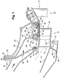
- the figure 1 schematically represents a portion of a turbomachine such as a turbojet or an airplane turboprop comprising a high-pressure turbine 10 arranged downstream of a combustion chamber 12, and upstream of a low-pressure turbine 14 of the turbomachine.
- a turbomachine such as a turbojet or an airplane turboprop comprising a high-pressure turbine 10 arranged downstream of a combustion chamber 12, and upstream of a low-pressure turbine 14 of the turbomachine.
- the combustion chamber 12 comprises a wall of internal revolution 48 and an outer wall of revolution 50 extending one inside the other.
- the inner wall 48 is connected at its downstream end to a radially outer end of a frustoconical wall 52 whose radially inner end has an annular flange 54 fixed to an inner casing 56 of the combustion chamber.
- the outer wall 50 of the chamber is connected at its downstream end to a radially inner end of a frustoconical wall 58 which has at its radially outer end a radially outer annular flange 60 for attachment to a corresponding annular flange 62 of an outer casing 64 of the room.
- the high-pressure turbine 10 comprises a single turbine stage comprising a distributor 16 formed of an annular row of stationary vanes for rectification, and a vane wheel 18 rotatably mounted downstream of the distributor 16.
- the low-pressure turbine 14 comprises several turbine stages, each of these stages also comprising a distributor and a paddle wheel, only the distributor 47 of the upstream low-pressure stage being visible in FIG. figure 1 .
- the impeller 18 of the high-pressure turbine 10 rotates within a substantially cylindrical assembly of ring sectors 20 which are circumferentially disposed end-to-end and suspended from a turbine casing 22 via a support 24.
- This annular support 24 comprises at its inner periphery means 26 for hooking ring sectors 20 and comprises a frustoconical wall 28 which extends upstream and outwards and is connected at its end. radially external to a radially outer annular flange 30 for fixing on a corresponding annular flange 32 of the turbine casing 22.
- This flange 30 is interposed axially between the flange 60 of the frustoconical wall 58 and the flange 32 of the turbine casing 22 and is clamped axially between these flanges by appropriate means of the flange. screw-nut type.
- the annular support 24 comprises at its inner periphery two radial annular walls 34, 36, respectively upstream and downstream, which are connected to one another by a cylindrical wall 38.
- the radial walls 34, 36 comprise at their radially internal ends downstream cylindrical flanges 40 which cooperate with circumferential hooks 42, 44 provided at the upstream and downstream ends of the ring sectors 20.
- An annular locking member 46 with a C-section is engaged axially from downstream on the downstream cylindrical rim 40 of the support and on the downstream hooks 44 of the ring sectors to ensure the locking of the assembly.
- the frustoconical wall 28 of the annular support 24 defines with the frustoconical wall 58 of the chamber an annular enclosure 80 which is supplied with ventilation and cooling air through orifices 82 formed in the frustoconical wall 58.
- Orifices 84 are formed in the wall radial upstream 34 of the annular support 24 to establish a fluid communication between the enclosure 80 and an annular cavity 86 for cooling the ring sectors 20 delimited externally by the cylindrical wall 38 of the annular support.
- the distributor 16 of the high-pressure turbine 10 is formed of two coaxial walls of revolution 66, 68 which extend one inside the other and which are interconnected by the fixed vanes of recovery.
- the inner wall 68 of the dispenser comprises an annular flange 70 which extends radially inwardly from its inner surface and which is secured by suitable means to a corresponding flange 72 provided at the downstream end of the inner casing 56 of the chamber
- the upstream and downstream ends of the inner wall 68 of the distributor cooperate to seal with the downstream end of the inner wall 48 of the combustion chamber and with the upstream end of the platforms of the blades of the wheel 18, respectively, to prevent the passage of gas from the annular flow vein of the turbine radially inwardly of the inner wall 68.
- the outer wall 66 of the distributor comprises at each of its upstream and downstream ends an annular groove 74 opening radially outwards.
- Annular sealing gaskets 76 are housed in these grooves 74 and cooperate with cylindrical ribs 78 formed on the frustoconical wall 58 and on the upstream radial wall 34 of the annular support 24, respectively, to prevent the passage of gas from the vein of the turbine radially outwardly of the outer wall 66, and conversely, the passage of air from the enclosure 80 radially inward in the vein of the turbine.
- the distributor 16 In operation of the turbomachine, the distributor 16 is biased downstream by the flow of gas in the turbine and its outer periphery which is not rigidly connected to a fixed element of the turbine moves slightly downstream until the radially outer end of the outer wall 66 of the distributor comes to bear axially on an upstream face of the upstream radial wall 34 of the annular support 24. The distributor 16 then exerts an axial force directed downstream on the support that is deformed and causes a displacement of the ring sectors 20 and a change of the radial clearances between the blades of the wheel 18 and the ring sectors.
- the invention makes it possible to provide a simple solution to this problem by means of the axial support of the external periphery of the distributor 16 on another fixed element of the turbine which is suspended from the outer casing 22 independently of the support 24 for securing the heating sectors. 'ring.
- the forces applied to the distributor are thus taken up by the fixed element and are therefore not transmitted to the support 24.
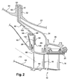
- this fixed element is formed by an annular plate 90 which extends radially around the axis of the turbine and around the distributor 16.
- This plate 90 has a substantially frustoconical shape and comprises at its radially outer end a radially outer annular flange 92 which is axially clamped between the flange 62 of the outer casing 64 and the flange. 30 of the annular support 24.
- the radially inner end of the sheet comprises a radial annular flange 94 which defines on the upstream side a bearing face of the distributor 16.
- the radially inner end of the sheet also comprises an annular groove 96 opening axially upstream.
- the outer wall 50 of the chamber is connected at its downstream end to a frustoconical wall 58 'which has a smaller radial dimension than the wall 58 of the figure 1 and which has at its radially outer end a cylindrical rim 98 facing downstream and engaged in the groove 96 of the sheet 90.
- the reduction of the radial dimension of the frustoconical wall 58 ' makes it possible to reduce the temperature differences between the ends radially inner and outer wall and thus increase its life.
- the sheet 90 further comprises orifices 100 of ventilation air passage for the air supply of the annular enclosure 80, these orifices 100 being evenly distributed around the axis of the turbine.
- the distributor 16 of the figure 2 includes internal 68 and outer 66 ferrules similar to those of the figure 1 , the outer ring 66 of the dispenser further comprising at its upstream end a radial annular flange 102 extending outwardly from its outer surface.
- This radial flange 102 comprises on the downstream side a cylindrical rib 104 bearing axially on the radial flange 94 of the sheet 90.
- the flange 102 extends substantially to the right of the attacking edges of the blades of the distributor .
- the distributor which is urged downstream by the hot gases leaving the combustion chamber transmits a portion of the forces to which it is subjected to the annular plate 90 by axial support of its radial flange 102 on the flange 94 of the sheet.
- the sheet may possibly deform elastically to ensure the resumption of efforts to which the distributor is subject.
- the flange 94 of the sheet is at a sufficient axial distance from the support 24 so as not to come into contact with the latter during operation. This support 24 is therefore no longer biased downstream by the distributor 16, which makes it possible to maintain constant radial clearances between the moving blades and the ring sectors 20.
Landscapes
- Engineering & Computer Science (AREA)
- Mechanical Engineering (AREA)
- General Engineering & Computer Science (AREA)
- Turbine Rotor Nozzle Sealing (AREA)
Applications Claiming Priority (1)
| Application Number | Priority Date | Filing Date | Title |
|---|---|---|---|
| FR0701427A FR2913050B1 (fr) | 2007-02-28 | 2007-02-28 | Turbine haute-pression d'une turbomachine |
Publications (4)
| Publication Number | Publication Date |
|---|---|
| EP1965027A2 true EP1965027A2 (de) | 2008-09-03 |
| EP1965027A8 EP1965027A8 (de) | 2008-10-29 |
| EP1965027A3 EP1965027A3 (de) | 2011-01-26 |
| EP1965027B1 EP1965027B1 (de) | 2012-01-25 |
Family
ID=38510942
Family Applications (1)
| Application Number | Title | Priority Date | Filing Date |
|---|---|---|---|
| EP08151865A Active EP1965027B1 (de) | 2007-02-28 | 2008-02-25 | Hochdruckturbine eines Turbinentriebwerks |
Country Status (4)
| Country | Link |
|---|---|
| US (1) | US8133018B2 (de) |
| EP (1) | EP1965027B1 (de) |
| CA (1) | CA2622116C (de) |
| FR (1) | FR2913050B1 (de) |
Cited By (4)
| Publication number | Priority date | Publication date | Assignee | Title |
|---|---|---|---|---|
| FR2944554A1 (fr) * | 2009-04-16 | 2010-10-22 | Snecma | Turbine haute-pression de turbomachine |
| DE102010036071A1 (de) * | 2010-09-01 | 2012-03-01 | Mtu Aero Engines Gmbh | Gehäuseseitige Struktur einer Turbomaschine |
| EP2481988A3 (de) * | 2011-01-28 | 2013-06-05 | Rolls-Royce Corporation | Brennkammerwandstütze und Dichtungsanordnung |
| FR3041029A1 (fr) * | 2015-09-11 | 2017-03-17 | Snecma | Distributeur d'une turbine basse pression, turbine basse pression et turbomachine associees |
Families Citing this family (12)
| Publication number | Priority date | Publication date | Assignee | Title |
|---|---|---|---|---|
| FR2921410B1 (fr) * | 2007-09-24 | 2010-03-12 | Snecma | Organe de verrouillage de secteurs d'anneau sur un carter de turbomachine, comprenant des moyens permettant sa prehension |
| JP2010174795A (ja) * | 2009-01-30 | 2010-08-12 | Mitsubishi Heavy Ind Ltd | タービン |
| US9482107B2 (en) * | 2009-09-28 | 2016-11-01 | Siemens Aktiengesellschaft | Gas turbine nozzle arrangement and gas turbine |
| JP4815536B2 (ja) * | 2010-01-12 | 2011-11-16 | 川崎重工業株式会社 | ガスタービンエンジンのシール構造 |
| US9115808B2 (en) * | 2012-02-13 | 2015-08-25 | General Electric Company | Transition piece seal assembly for a turbomachine |
| US9410441B2 (en) * | 2012-09-13 | 2016-08-09 | Pratt & Whitney Canada Corp. | Turboprop engine with compressor turbine shroud |
| JP6266775B2 (ja) | 2013-07-26 | 2018-01-24 | エムアールエイ・システムズ・エルエルシー | 航空機エンジンパイロン |
| DE102014209057A1 (de) * | 2014-05-14 | 2015-11-19 | MTU Aero Engines AG | Gasturbinengehäuseanordnung |
| ES2758187T3 (es) * | 2017-02-17 | 2020-05-04 | MTU Aero Engines AG | Disposición de sellado para una turbina de gas |
| FR3087232B1 (fr) * | 2018-10-12 | 2021-06-25 | Safran Aircraft Engines | Turbomachine comprenant un rotor portant des pales a calage variable |
| FR3096723B1 (fr) * | 2019-05-29 | 2022-03-25 | Safran Helicopter Engines | Anneau d’etancheite pour une roue de turbine de turbomachine |
| US11248485B1 (en) * | 2020-08-17 | 2022-02-15 | General Electric Company | Systems and apparatus to control deflection mismatch between static and rotating structures |
Citations (4)
| Publication number | Priority date | Publication date | Assignee | Title |
|---|---|---|---|---|
| US3314648A (en) | 1961-12-19 | 1967-04-18 | Gen Electric | Stator vane assembly |
| US4023919A (en) | 1974-12-19 | 1977-05-17 | General Electric Company | Thermal actuated valve for clearance control |
| EP0083896A1 (de) | 1982-01-07 | 1983-07-20 | Societe Nationale D'etude Et De Construction De Moteurs D'aviation, "S.N.E.C.M.A." | Kühlvorrichtung für die Abdeckplatten der Rotorschaufeln einer Turbine |
| US4485620A (en) | 1982-03-03 | 1984-12-04 | United Technologies Corporation | Coolable stator assembly for a gas turbine engine |
Family Cites Families (16)
| Publication number | Priority date | Publication date | Assignee | Title |
|---|---|---|---|---|
| US3367628A (en) * | 1966-10-31 | 1968-02-06 | United Aircraft Corp | Movable vane unit |
| US3372542A (en) * | 1966-11-25 | 1968-03-12 | United Aircraft Corp | Annular burner for a gas turbine |
| US3842595A (en) * | 1972-12-26 | 1974-10-22 | Gen Electric | Modular gas turbine engine |
| FR2280791A1 (fr) * | 1974-07-31 | 1976-02-27 | Snecma | Perfectionnements au reglage du jeu entre les aubes et le stator d'une turbine |
| US3966352A (en) * | 1975-06-30 | 1976-06-29 | United Technologies Corporation | Variable area turbine |
| GB1605297A (en) * | 1977-05-05 | 1988-06-08 | Rolls Royce | Nozzle guide vane structure for a gas turbine engine |
| US4214851A (en) * | 1978-04-20 | 1980-07-29 | General Electric Company | Structural cooling air manifold for a gas turbine engine |
| DE3003470C2 (de) * | 1980-01-31 | 1982-02-25 | MTU Motoren- und Turbinen-Union München GmbH, 8000 München | Turbinenleitschaufelaufhängung für Gasturbinenstrahltriebwerke |
| DE3003469C2 (de) * | 1980-01-31 | 1987-03-19 | MTU Motoren- und Turbinen-Union München GmbH, 8000 München | Einrichtung zur Verbindung einander rotationssymmetrisch zugeordneter, unterschiedlichen thermischen Einflüssen ausgesetzter Bauteile für Strömungsmaschinen, insbesondere Gasturbinentriebwerke |
| FR2604750B1 (fr) * | 1986-10-01 | 1988-12-02 | Snecma | Turbomachine munie d'un dispositif de commande automatique des debits de ventilation de turbine |
| GB2206651B (en) * | 1987-07-01 | 1991-05-08 | Rolls Royce Plc | Turbine blade shroud structure |
| US4820116A (en) * | 1987-09-18 | 1989-04-11 | United Technologies Corporation | Turbine cooling for gas turbine engine |
| US5118120A (en) * | 1989-07-10 | 1992-06-02 | General Electric Company | Leaf seals |
| US5332358A (en) * | 1993-03-01 | 1994-07-26 | General Electric Company | Uncoupled seal support assembly |
| JP4060981B2 (ja) * | 1998-04-08 | 2008-03-12 | 本田技研工業株式会社 | ガスタービンの静翼構造体及びそのユニット |
| GB9820226D0 (en) * | 1998-09-18 | 1998-11-11 | Rolls Royce Plc | Gas turbine engine casing |
-
2007
- 2007-02-28 FR FR0701427A patent/FR2913050B1/fr active Active
-
2008
- 2008-02-25 EP EP08151865A patent/EP1965027B1/de active Active
- 2008-02-27 US US12/038,604 patent/US8133018B2/en active Active
- 2008-02-27 CA CA2622116A patent/CA2622116C/fr active Active
Patent Citations (4)
| Publication number | Priority date | Publication date | Assignee | Title |
|---|---|---|---|---|
| US3314648A (en) | 1961-12-19 | 1967-04-18 | Gen Electric | Stator vane assembly |
| US4023919A (en) | 1974-12-19 | 1977-05-17 | General Electric Company | Thermal actuated valve for clearance control |
| EP0083896A1 (de) | 1982-01-07 | 1983-07-20 | Societe Nationale D'etude Et De Construction De Moteurs D'aviation, "S.N.E.C.M.A." | Kühlvorrichtung für die Abdeckplatten der Rotorschaufeln einer Turbine |
| US4485620A (en) | 1982-03-03 | 1984-12-04 | United Technologies Corporation | Coolable stator assembly for a gas turbine engine |
Cited By (7)
| Publication number | Priority date | Publication date | Assignee | Title |
|---|---|---|---|---|
| FR2944554A1 (fr) * | 2009-04-16 | 2010-10-22 | Snecma | Turbine haute-pression de turbomachine |
| DE102010036071A1 (de) * | 2010-09-01 | 2012-03-01 | Mtu Aero Engines Gmbh | Gehäuseseitige Struktur einer Turbomaschine |
| US9540953B2 (en) | 2010-09-01 | 2017-01-10 | Mtu Aero Engines Gmbh | Housing-side structure of a turbomachine |
| EP2481988A3 (de) * | 2011-01-28 | 2013-06-05 | Rolls-Royce Corporation | Brennkammerwandstütze und Dichtungsanordnung |
| US8752395B2 (en) | 2011-01-28 | 2014-06-17 | Rolls-Royce Corporation | Combustor liner support and seal assembly |
| FR3041029A1 (fr) * | 2015-09-11 | 2017-03-17 | Snecma | Distributeur d'une turbine basse pression, turbine basse pression et turbomachine associees |
| FR3041028A1 (fr) * | 2015-09-11 | 2017-03-17 | Snecma | Distributeur d'une turbine basse pression, turbine basse pression et turbomachine associees |
Also Published As
| Publication number | Publication date |
|---|---|
| FR2913050B1 (fr) | 2011-06-17 |
| US8133018B2 (en) | 2012-03-13 |
| EP1965027A8 (de) | 2008-10-29 |
| FR2913050A1 (fr) | 2008-08-29 |
| US20080267768A1 (en) | 2008-10-30 |
| EP1965027A3 (de) | 2011-01-26 |
| EP1965027B1 (de) | 2012-01-25 |
| CA2622116C (fr) | 2015-08-11 |
| CA2622116A1 (fr) | 2008-08-28 |
Similar Documents
| Publication | Publication Date | Title |
|---|---|---|
| EP1965027B1 (de) | Hochdruckturbine eines Turbinentriebwerks | |
| EP3523507B1 (de) | Bewegliche ringanordnung für eine turbine eines turbinenmotors | |
| EP2060743B1 (de) | Abdichtigung eines Turbinenleitschaufelrings in einer Turbinenstufe | |
| EP2071142B1 (de) | Dichtigkeit eines Nabenhohlraums eines Austrittsgehäuses in einem Turbotriebwerk | |
| EP1265031B1 (de) | Befestigung von metallischen Aufsätzen auf CMC-Turbomaschinenbrennkammerwänden | |
| EP1965034B1 (de) | Turbinenstufe in einer Strömungsmaschine | |
| EP2504529B1 (de) | Isolierung einer umlaufenden kante eines aussengehäuses eines turbinenmotors aus einem entsprechenden ringsektor | |
| EP2300688B1 (de) | Hochdruckturbine für turbomotor mit verbesserter befestigung des gehäuses zur steuerung des radialspiels beweglicher schaufeln | |
| EP1517005A1 (de) | Gasturbine mit einem Abdichtdelement mit Lamellenstruktur | |
| FR3018548A1 (fr) | Turboreacteur a conduit de decharge | |
| EP3421730B1 (de) | Turbine für strömungsmaschine mit dichtring bestehend aus zwei teilen | |
| EP2060751B1 (de) | Turbinen- oder Kompressorstufe eines Turbotriebwerks | |
| EP3880939B1 (de) | Dichtung zwischen einer welle und einer leitschaufel einer turbomaschine | |
| FR3071273A1 (fr) | Ensemble d'etancheite de turbine pour turbomachine | |
| FR2978793A1 (fr) | Rotor de turbine pour une turbomachine | |
| EP1519009A1 (de) | Turbomaschine mit Luftentnahme für die Kabine über ein Kugelgelengrohr | |
| FR2961848A1 (fr) | Etage de turbine | |
| FR3058755A1 (fr) | Turbine pour turbomachine | |
| EP3721058B1 (de) | Verbindung zwischen einem leitkranzsektor aus verbundwerkstoff mit keramischer matrix und einem metallischen träger einer turbine einer turbomaschine | |
| FR2961556A1 (fr) | Isolation du carter externe d'une turbine de turbomachine vis-a-vis d'un anneau sectorise | |
| FR3101374A1 (fr) | Structure de refroidissement d’une turbine avec coopération radiale entre anneau d’étanchéité et disque de roue mobile | |
| FR3116305A1 (fr) | Arbre de liaison d’un corps haute pression d’une turbomachine | |
| FR3094398A1 (fr) | Ensemble pour un rotor de turbomachine | |
| FR3147834A1 (fr) | Ensemble rotorique de turbine pour turbomachine | |
| FR3163100A1 (fr) | Secteur d’anneau d’etancheite pour une turbine de turbomachine d’aeronef |
Legal Events
| Date | Code | Title | Description |
|---|---|---|---|
| PUAI | Public reference made under article 153(3) epc to a published international application that has entered the european phase |
Free format text: ORIGINAL CODE: 0009012 |
|
| AK | Designated contracting states |
Kind code of ref document: A2 Designated state(s): AT BE BG CH CY CZ DE DK EE ES FI FR GB GR HR HU IE IS IT LI LT LU LV MC MT NL NO PL PT RO SE SI SK TR |
|
| AX | Request for extension of the european patent |
Extension state: AL BA MK RS |
|
| RAP1 | Party data changed (applicant data changed or rights of an application transferred) |
Owner name: SNECMA |
|
| PUAL | Search report despatched |
Free format text: ORIGINAL CODE: 0009013 |
|
| AK | Designated contracting states |
Kind code of ref document: A3 Designated state(s): AT BE BG CH CY CZ DE DK EE ES FI FR GB GR HR HU IE IS IT LI LT LU LV MC MT NL NO PL PT RO SE SI SK TR |
|
| AX | Request for extension of the european patent |
Extension state: AL BA MK RS |
|
| 17P | Request for examination filed |
Effective date: 20110218 |
|
| RIC1 | Information provided on ipc code assigned before grant |
Ipc: F01D 9/04 20060101AFI20110518BHEP Ipc: F01D 25/24 20060101ALI20110518BHEP Ipc: F01D 11/12 20060101ALI20110518BHEP |
|
| GRAP | Despatch of communication of intention to grant a patent |
Free format text: ORIGINAL CODE: EPIDOSNIGR1 |
|
| AKX | Designation fees paid |
Designated state(s): DE FR GB |
|
| GRAS | Grant fee paid |
Free format text: ORIGINAL CODE: EPIDOSNIGR3 |
|
| GRAA | (expected) grant |
Free format text: ORIGINAL CODE: 0009210 |
|
| AK | Designated contracting states |
Kind code of ref document: B1 Designated state(s): DE FR GB |
|
| REG | Reference to a national code |
Ref country code: GB Ref legal event code: FG4D Free format text: NOT ENGLISH |
|
| REG | Reference to a national code |
Ref country code: DE Ref legal event code: R096 Ref document number: 602008012819 Country of ref document: DE Effective date: 20120322 |
|
| PLBE | No opposition filed within time limit |
Free format text: ORIGINAL CODE: 0009261 |
|
| STAA | Information on the status of an ep patent application or granted ep patent |
Free format text: STATUS: NO OPPOSITION FILED WITHIN TIME LIMIT |
|
| 26N | No opposition filed |
Effective date: 20121026 |
|
| REG | Reference to a national code |
Ref country code: DE Ref legal event code: R097 Ref document number: 602008012819 Country of ref document: DE Effective date: 20121026 |
|
| REG | Reference to a national code |
Ref country code: FR Ref legal event code: PLFP Year of fee payment: 9 |
|
| REG | Reference to a national code |
Ref country code: FR Ref legal event code: PLFP Year of fee payment: 10 |
|
| REG | Reference to a national code |
Ref country code: FR Ref legal event code: PLFP Year of fee payment: 11 |
|
| REG | Reference to a national code |
Ref country code: FR Ref legal event code: CD Owner name: SAFRAN AIRCRAFT ENGINES, FR Effective date: 20170719 |
|
| PGFP | Annual fee paid to national office [announced via postgrant information from national office to epo] |
Ref country code: GB Payment date: 20260219 Year of fee payment: 19 |
|
| PGFP | Annual fee paid to national office [announced via postgrant information from national office to epo] |
Ref country code: DE Payment date: 20260217 Year of fee payment: 19 |
|
| PGFP | Annual fee paid to national office [announced via postgrant information from national office to epo] |
Ref country code: FR Payment date: 20260219 Year of fee payment: 19 |