EP0084006B1 - Elektrischer Kochherd - Google Patents
Elektrischer Kochherd Download PDFInfo
- Publication number
- EP0084006B1 EP0084006B1 EP19830400030 EP83400030A EP0084006B1 EP 0084006 B1 EP0084006 B1 EP 0084006B1 EP 19830400030 EP19830400030 EP 19830400030 EP 83400030 A EP83400030 A EP 83400030A EP 0084006 B1 EP0084006 B1 EP 0084006B1
- Authority
- EP
- European Patent Office
- Prior art keywords
- heating element
- fan
- turbine
- oven
- muffle
- Prior art date
- Legal status (The legal status is an assumption and is not a legal conclusion. Google has not performed a legal analysis and makes no representation as to the accuracy of the status listed.)
- Expired
Links
- 238000010411 cooking Methods 0.000 title claims description 17
- 238000010438 heat treatment Methods 0.000 claims description 31
- 238000004140 cleaning Methods 0.000 claims description 2
- 238000000197 pyrolysis Methods 0.000 claims description 2
- 238000010586 diagram Methods 0.000 description 8
- 235000014594 pastries Nutrition 0.000 description 8
- 235000013399 edible fruits Nutrition 0.000 description 3
- 235000012976 tarts Nutrition 0.000 description 3
- 230000003197 catalytic effect Effects 0.000 description 1
- 230000001276 controlling effect Effects 0.000 description 1
- 238000005265 energy consumption Methods 0.000 description 1
- 235000013372 meat Nutrition 0.000 description 1
- 238000000034 method Methods 0.000 description 1
- 235000011835 quiches Nutrition 0.000 description 1
- 230000005855 radiation Effects 0.000 description 1
- 230000001105 regulatory effect Effects 0.000 description 1
- 239000000523 sample Substances 0.000 description 1
- 238000010257 thawing Methods 0.000 description 1
- 210000003462 vein Anatomy 0.000 description 1
Images

Classifications
-
- F—MECHANICAL ENGINEERING; LIGHTING; HEATING; WEAPONS; BLASTING
- F24—HEATING; RANGES; VENTILATING
- F24C—DOMESTIC STOVES OR RANGES ; DETAILS OF DOMESTIC STOVES OR RANGES, OF GENERAL APPLICATION
- F24C15/00—Details
- F24C15/32—Arrangements of ducts for hot gases, e.g. in or around baking ovens
- F24C15/322—Arrangements of ducts for hot gases, e.g. in or around baking ovens with forced circulation
- F24C15/325—Arrangements of ducts for hot gases, e.g. in or around baking ovens with forced circulation electrically-heated
Definitions
- the present invention relates to domestic electric cooking ovens of the type comprising a muffle in which are mounted at least one vault heating element, at least one hearth heating element, an air circulation turbine provided in the rear wall. muffle, a heating element placed in the air flow stream of the turbine, an air ducting means arranged to direct the air blown by the turbine in roughly horizontal veins in the cavity of the muffle, and an electrical switching device for the selective energization of said heating elements and said turbine.
- Such ovens have already been described for example in DE-A-2 657 929. Their switching device is arranged. so that the user can place the oven in a first configuration called “conventional”, in which are energized exclusively, the vault and bottom elements and also in a second configuration, in which only the heating element of the turbine and this turbine itself is in action.
- This second configuration is commonly called “fan heat”.
- the object of the invention is to provide a domestic cooking oven of the type defined above, but without the abovementioned drawbacks.
- this oven is characterized in that said switching device comprises a position in which it is able to connect said turbine heating element in series with the roof heating element or elements, while energizing said turbine and said bottom heating element, in parallel with said elements connected in series.
- the oven can be placed in a so-called mixed configuration in which the hearth heating element operates at full power, while the vault and turbine heating elements consume only a relatively low power, the heat which they generate being conveyed in any ia cavity of the furnace.
- the dish receives a high amount of heat from below by radiation and convection (for example for cooking a moist pie shell) while the sum of the heat supplied by the other resistances leads to a shorter cooking time than would be necessary in the other configurations of the oven. This therefore not only results in a better culinary result, but also a saving of up to 8% for a moist pastry in comparison with the fan-assisted configuration.
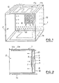
- FIGs. 1 and 2 there is shown schematically an oven muffle 1 delimiting a cooking cavity 2 which, of course, is closed by a door (not shown) during cooking.
- a turbine 4 driven by an electric motor 5, the discharge openings of the turbine being surrounded by a turbine resistor 6 formed for example by two coaxial turns.
- the suction side of the turbine is placed in front of the central opening 7 of an air duct plate 8 in front of which a filter 9 is mounted.
- the duct plate 8 has discharge orifices 10 at its periphery.
- Arch heating elements 11 a and 11 b are mounted at the top of the muffle parallel to its arch wall.
- a temperature sensor 12 controlling a thermostat contact 13 is placed next to the roof resistor 11 b.
- a hearth heating element 14 or hearth resistance is arranged below the bottom wall of the muffle 1.
- Contact A is connected to terminal 15 and is connected in series with the rest of the circuit to control power-up or cut-off.
- the motor 5 of the turbine 4 is connected in series with the contact B between the contact A and the terminal 16.
- the thermostatic contact 13 reacting to the probe 12 is connected between the contact A and a circuit which includes the heating elements of the oven .
- the turbine heating element 6 is connected between the thermostatic contact 13 and a junction point 17 to which the grill and arch elements 11 a and 11b are connected in series with the respective contacts D and F, all being connected in parallel to contact E of the switching means.
- the floor resistor 14 is mounted in series with the contact G between the contact 13 and the terminal 16.
- FIG. 4 shows that the oven according to the invention can be placed, by means of a simple switching with a single button, not only in the conventional configurations such as “fan heat and” conventional “(positions c and i), but also in a so-called configuration "Mixed during which the oven is heated by the hearth resistance 14 providing a significant amount of heat from the bottom of the muffle and by the series connection of the turbine resistance 6 on the one hand and the parallel connection of the resistors of the vault 11a a and 11b on the other hand, the heat generated of which is conveyed and regularly distributed in the muffle thanks to the rotation of the turbine 4. This is here position d of FIG. 4.
- the oven according to the invention therefore combines all the advantages of the two conventional cooking methods mentioned above as well as those resulting from the third "mixed" configuration. These particular advantages are in particular a better horizontal distribution of the heat in the oven, the contribution of calories being better distributed in particular by placing the floor resistance in series and paralleling the vault resistors in series with the turbine resistance.
- Fig. 5 shows by way of comparison two diagrams of the temperature as a function of the time corresponding to the baking of a pastry of the aforementioned kind.
- Diagram (a) shows the energy expenditure for the "circulating heat” configuration (position c), while diagram (b) shows this expenditure in mixed configuration (position d).
Landscapes
- Engineering & Computer Science (AREA)
- Chemical & Material Sciences (AREA)
- Combustion & Propulsion (AREA)
- Mechanical Engineering (AREA)
- General Engineering & Computer Science (AREA)
- Baking, Grill, Roasting (AREA)
Claims (3)
Applications Claiming Priority (2)
| Application Number | Priority Date | Filing Date | Title |
|---|---|---|---|
| FR8200089 | 1982-01-06 | ||
| FR8200089A FR2519413B1 (fr) | 1982-01-06 | 1982-01-06 | Four electrique de cuisson domestique |
Publications (2)
| Publication Number | Publication Date |
|---|---|
| EP0084006A1 EP0084006A1 (de) | 1983-07-20 |
| EP0084006B1 true EP0084006B1 (de) | 1986-04-16 |
Family
ID=9269735
Family Applications (1)
| Application Number | Title | Priority Date | Filing Date |
|---|---|---|---|
| EP19830400030 Expired EP0084006B1 (de) | 1982-01-06 | 1983-01-05 | Elektrischer Kochherd |
Country Status (3)
| Country | Link |
|---|---|
| EP (1) | EP0084006B1 (de) |
| DE (1) | DE3362968D1 (de) |
| FR (1) | FR2519413B1 (de) |
Families Citing this family (11)
| Publication number | Priority date | Publication date | Assignee | Title |
|---|---|---|---|---|
| FR2552531B1 (fr) * | 1983-09-23 | 1986-11-21 | Europ Equip Menager | Enceinte de cuisson a energie electrique |
| FR2562991B1 (fr) * | 1984-04-11 | 1986-06-06 | Europ Equip Menager | Enceinte de cuisson a energie electrique |
| DE3447481A1 (de) * | 1984-12-27 | 1986-07-03 | Küppersbusch AG, 4650 Gelsenkirchen | Bratroehre mit selbsttaetiger beseitigung von geruchs- u. verschmutzungsteilchen in der bratroehrenluft |
| FR2592467B1 (fr) * | 1985-04-09 | 1988-04-29 | Europ Equip Menager | Enceinte de cuisson a energie electrique |
| FR2697321B1 (fr) * | 1992-10-26 | 1997-04-25 | Moulinex Sa | Four électrique de cuisson domestique par gril ou par convection forcée. |
| DE4319613C1 (de) * | 1993-06-14 | 1994-06-30 | Bauknecht Hausgeraete | Verfahren zum Betreiben eines Elektrobackofens |
| DE59302937D1 (de) * | 1993-08-23 | 1996-07-18 | Bauknecht Hausgeraete | Backofen |
| DE10151937A1 (de) * | 2001-10-22 | 2003-04-30 | Bsh Bosch Siemens Hausgeraete | Gargerät mit einer Schnellaufheizeinheit |
| EP1992879A1 (de) | 2007-05-16 | 2008-11-19 | Electrolux Home Products Corporation N.V. | Backofen, insbesondere Haushaltsbackofen |
| KR20090021037A (ko) | 2007-08-24 | 2009-02-27 | 엘지전자 주식회사 | 다중 브로일 히터를 구비한 전기 오븐 및 이 전기 오븐의프리히팅 방법 |
| EP2848866B1 (de) * | 2013-09-17 | 2020-02-05 | Electrolux Appliances Aktiebolag | Back- und/oder Garofen und Verfahren zum Betreiben eines Back- und/oder Garofens |
Family Cites Families (3)
| Publication number | Priority date | Publication date | Assignee | Title |
|---|---|---|---|---|
| DE2657929C3 (de) * | 1976-12-21 | 1980-03-20 | Bosch-Siemens Hausgeraete Gmbh, 7000 Stuttgart | Backofen, insbesondere mit Mitteln zur pyrolytischen Selbstreinigung |
| DE2658686C3 (de) * | 1976-12-23 | 1980-02-07 | Bosch-Siemens Hausgeraete Gmbh, 7000 Stuttgart | Backofen mit einem Umluftgeblase fur die Heißluftumwälzung |
| DE2757059C2 (de) * | 1977-12-21 | 1985-05-02 | Bosch-Siemens Hausgeräte GmbH, 7000 Stuttgart | Backofen mit Umluftgebläse und Stahlungsheizkörpern |
-
1982
- 1982-01-06 FR FR8200089A patent/FR2519413B1/fr not_active Expired
-
1983
- 1983-01-05 EP EP19830400030 patent/EP0084006B1/de not_active Expired
- 1983-01-05 DE DE8383400030T patent/DE3362968D1/de not_active Expired
Also Published As
| Publication number | Publication date |
|---|---|
| FR2519413B1 (fr) | 1987-05-22 |
| DE3362968D1 (en) | 1986-05-22 |
| FR2519413A1 (fr) | 1983-07-08 |
| EP0084006A1 (de) | 1983-07-20 |
Similar Documents
| Publication | Publication Date | Title |
|---|---|---|
| EP1215444B2 (de) | Ofen und Verfahren zu seiner Steuerung | |
| EP0084006B1 (de) | Elektrischer Kochherd | |
| EP0447979B1 (de) | Verfahren zum Backen für einen Ofen mit Mikrowellen-, Konvektions- und Infrarotheizung | |
| JP2010538613A (ja) | 変更可能な一括調理用の自動焼き機 | |
| US4535226A (en) | Domestic electric cooking oven | |
| FR2638627A1 (de) | ||
| EP0606440A1 (de) | Verfahren zum rösten und/oder erwärmen eines agronahrungsmittelprodukt und einrichtung zur ausführung dieses verfahrens | |
| EP0151894A2 (de) | Tragbares Back- und Bratgerät mit Backraum und Bratplatte | |
| EP0402257B1 (de) | Brotröster mit mehreren Funktionen | |
| EP0161161A1 (de) | Kochraum mit elektrischer Beheizung | |
| CH631537A5 (fr) | Four domestique a gaz a deux enceintes de cuisson. | |
| US7339137B1 (en) | Electric grilling appliance | |
| FR2463363A1 (fr) | Four de cuisson d'aliments multifonctionnel | |
| EP4303494B1 (de) | Vorrichtung zum auftauen/erhitzen/erhitzen von lebensmitteln, insbesondere auf teigbasis, wie pizza oder torten | |
| FR3071043A1 (fr) | Dispositif de chauffage pour un four a pizza electrique destine a cuire des produits frais ou congeles caracterises selon un procede en deux phases de cuissons successives | |
| FR2491595A1 (fr) | Four de cuisine a vapeur et procede pour son utilisation | |
| EP0595083B1 (de) | Haushaltsofen | |
| FR2548764A1 (fr) | Four electrique a usage menager | |
| EP0950861B1 (de) | Verfahren zum Kochen von Nahrungsmitteln in einem Garofen | |
| FR2696630A1 (fr) | Four de cuisson pour produits alimentaires type pain... etc. | |
| FR2552531A1 (fr) | Enceinte de cuisson a energie electrique | |
| FR3146195A3 (fr) | Dispositif de décongélation et/ou de cuisson d’un produit alimentaire et procédé de réglage d’un tel dispositif | |
| JP2009041818A (ja) | 蒸気調理器 | |
| FR2552530A1 (fr) | Enceinte de cuisson a energie electrique | |
| FR2943486A1 (fr) | Appareil de cuisson electromenager |
Legal Events
| Date | Code | Title | Description |
|---|---|---|---|
| PUAI | Public reference made under article 153(3) epc to a published international application that has entered the european phase |
Free format text: ORIGINAL CODE: 0009012 |
|
| AK | Designated contracting states |
Designated state(s): BE DE GB IT NL |
|
| 17P | Request for examination filed |
Effective date: 19830708 |
|
| ITF | It: translation for a ep patent filed | ||
| GRAA | (expected) grant |
Free format text: ORIGINAL CODE: 0009210 |
|
| AK | Designated contracting states |
Kind code of ref document: B1 Designated state(s): BE DE GB IT NL |
|
| REF | Corresponds to: |
Ref document number: 3362968 Country of ref document: DE Date of ref document: 19860522 |
|
| PLBE | No opposition filed within time limit |
Free format text: ORIGINAL CODE: 0009261 |
|
| STAA | Information on the status of an ep patent application or granted ep patent |
Free format text: STATUS: NO OPPOSITION FILED WITHIN TIME LIMIT |
|
| 26N | No opposition filed | ||
| ITTA | It: last paid annual fee | ||
| PGFP | Annual fee paid to national office [announced via postgrant information from national office to epo] |
Ref country code: GB Payment date: 19941219 Year of fee payment: 13 |
|
| PGFP | Annual fee paid to national office [announced via postgrant information from national office to epo] |
Ref country code: BE Payment date: 19950104 Year of fee payment: 13 |
|
| PGFP | Annual fee paid to national office [announced via postgrant information from national office to epo] |
Ref country code: NL Payment date: 19950131 Year of fee payment: 13 |
|
| PG25 | Lapsed in a contracting state [announced via postgrant information from national office to epo] |
Ref country code: GB Effective date: 19960105 |
|
| PG25 | Lapsed in a contracting state [announced via postgrant information from national office to epo] |
Ref country code: BE Effective date: 19960131 |
|
| BERE | Be: lapsed |
Owner name: DE DIETRICH & CIE Effective date: 19960131 |
|
| PG25 | Lapsed in a contracting state [announced via postgrant information from national office to epo] |
Ref country code: NL Effective date: 19960801 |
|
| GBPC | Gb: european patent ceased through non-payment of renewal fee |
Effective date: 19960105 |
|
| NLV4 | Nl: lapsed or anulled due to non-payment of the annual fee |
Effective date: 19960801 |
|
| PGFP | Annual fee paid to national office [announced via postgrant information from national office to epo] |
Ref country code: DE Payment date: 20020213 Year of fee payment: 20 |