EP0084137A2 - Vérification de notes bancaires - Google Patents
Vérification de notes bancaires Download PDFInfo
- Publication number
- EP0084137A2 EP0084137A2 EP82111719A EP82111719A EP0084137A2 EP 0084137 A2 EP0084137 A2 EP 0084137A2 EP 82111719 A EP82111719 A EP 82111719A EP 82111719 A EP82111719 A EP 82111719A EP 0084137 A2 EP0084137 A2 EP 0084137A2
- Authority
- EP
- European Patent Office
- Prior art keywords
- note
- test
- patch
- document
- images
- Prior art date
- Legal status (The legal status is an assumption and is not a legal conclusion. Google has not performed a legal analysis and makes no representation as to the accuracy of the status listed.)
- Granted
Links
Images


Classifications
-
- G—PHYSICS
- G07—CHECKING-DEVICES
- G07D—HANDLING OF COINS OR VALUABLE PAPERS, e.g. TESTING, SORTING BY DENOMINATIONS, COUNTING, DISPENSING, CHANGING OR DEPOSITING
- G07D7/00—Testing specially adapted to determine the identity or genuineness of valuable papers or for segregating those which are unacceptable, e.g. banknotes that are alien to a currency
- G07D7/06—Testing specially adapted to determine the identity or genuineness of valuable papers or for segregating those which are unacceptable, e.g. banknotes that are alien to a currency using wave or particle radiation
- G07D7/12—Visible light, infrared or ultraviolet radiation
-
- G—PHYSICS
- G07—CHECKING-DEVICES
- G07D—HANDLING OF COINS OR VALUABLE PAPERS, e.g. TESTING, SORTING BY DENOMINATIONS, COUNTING, DISPENSING, CHANGING OR DEPOSITING
- G07D7/00—Testing specially adapted to determine the identity or genuineness of valuable papers or for segregating those which are unacceptable, e.g. banknotes that are alien to a currency
- G07D7/181—Testing mechanical properties or condition, e.g. wear or tear
Definitions
- Inspection of newly printed currency or similar documents is a necessary step in its production process to insure that flawed documents do not reach the public. Inspection is also a means of discovering defects in the machinery used in producing the notes.
- One typical apparatus for automatic inspection of currency notes comprises optical scanner means past which the notes are transported. The data obtained by scanning is then compared with corresponding data representative of a perfect master note stored in a memory. In such systems it is critical that data being scanned on the test note be registered with the data being read out of memory to assure that exactly corresponding areas of the test and stored master note are being compared.
- Such a memory registration system is disclosed in U.S. Patent Application S.N. 957,767 entitled Memory Registration System, filed November 3, 1978 having the same assignee as the present application.
- Such systems require a scanning system, a master note memory, and means for registering the test note with the stored master note and are relatively simple in concept since they are used in the inspection of currency produced by a single printing process such as used in printing U.S. currency. In such a prcess only one image is formed on the note.
- the present invention relates to an apparatus which overcomes the above mentioned problems by effectively generating in real time a master note for each test note scanned.
- the present invention relates to an apparatus for the flaw inspection of currency or similar documents in which two images are superimposed by two separate printing processes and wherein misregistration between these two images is acceptable up to a predetermined maximum tolerance.
- the present invention solves a second order polynomial equation to generate each reference patch value of the plurality of the reference patch values which make up a perfect hypothetical or synthetic master note having the same image misregister as a test note being scanned in real time.
- the technique may be regarded as a process in which a reference patch stored in the master note memory is modified to conform exactly to a specific test patch being examined in real time. Ideally, the modification is such that if the test is obtained from an acceptable note the difference between the reference and test patch is zero.
- each solution of the polynomial equation provides a number representative of the reflectance of a reference patch value integrated over the area of the reference patch.
- All reference patch values generated for the hypothetical master note are peculiar to the particular test note being scanned and compensate for the misregistration of the two images peculiar to the particular test note being scanned. If the misregistration between images of the test note being scanned exceeds the predetermined maximum tolerance the test note is rejected as unacceptable.
- Each reference patch value generated is registered with and compared to its counterpart patch value obtained by scanning the test note which is accepted only if the comparisons meet preestablished criteria. Once the hypothetical master note is generated, the comparison with its associated test note is equivalent to comparing a previously stored master note with a scanned test note as is done in the quality inspection of United States currency.
- the number of constants and variables in the polynomial equation that must be solved for each reference patch value is dependent on the number of images printed on the currency notes or like documents to be inspected.
- a polynomial equation of fifteen constants and four variables has been found adequate to provide acceptable approximations of the reference patch values of the reference note.
- a different set of constants and variables are required for the solution of each reference patch value.
- the present invention comprises a reference patch value generator subsystem which formulates a set of four variables for each patch of a scanned test note.
- the reference patch value generator subsystem formulates the address of the required set of the fifteen constants which together with the four variables are required for the solution of the polynomial equation associated with each particular reference patch value of the master note.
- Memory means store a large number of previously calculated constants fifteen of which are addressed and brought out of memory by the reference patch value generator for the real time solution of each reference patch value of the master note.
- the reference patch value generator subsystem comprises cross-correlation means which receives high resolution registration data via high resolution scanner means representative of three intaglio and three lithographic patches on the test note and correlates this with corresponding patches stored in memory representative of intaglio and lithographic master note information stored in memory.
- the cross-correlation.means establishes "fixes" between local areas on the test note and corresponding areas on the reference note. These fixes consist of two coordinates defining the centroid of a local area on one test note and two coordinates defining the centroid of the same image (intaglio or lithographic) on the master notes. These local images are selected to be predominately intaglio or litho.
- a minimum of 3 fixes is obtained for each image (intaglio and litho). These fixes are used to derive the constants in a transformation equation which relate corresponding points on reference and test images. When two images are present this process is performed twice. The first time, for example, the corresponding points are corresponding points in the intaglio images and the intaglio transformation constants are determined in the intaglio coefficient processor. The second time the corresponding points are corresponding points in the litho images and the litho transformation constants are determined in the litho coefficient processor. The centroid of each test patch is transformed onto the master note twice, once using the intaglio transformation constants and once using the litho transformation constants.
- the above four variables and fifteen constants are transmitted to a reference patch value processor which solves the polynomial equation for the appropriate patch reference value which is provided as an input to an exceedance detector.
- An inspection scanner provides inputs to the exceedance detector wherein the test patch value is compared with its corresponding reference patch value from the master note. After the test note has been completely compared with the hypothetical master note, a determination is made of the acceptability or unacceptability of the test note.
- the present invention instead of storing a perfect master note and comparing it to each test note scanned the present invention generates a hypothetical synthetic master note having the same misregistration between image as the test note scanned.
- the present invention utilizes a series approximation technique which divides the computational burden between the real time on-line processor and off-line, previously calculated and stored data which together with the data provided by scanning each test note is processed to generate a synthetic master note memory.
- the synthetic master note memory is essentially a mathematical representation of a note in any allowable misregistration.
- the mathematical representation is a string of derived constants which are the coefficients of a four variable Taylor series expansion.
- the four variables are generated in real time for each examination patch on the test note and represents the actual location at these patches of the intaglio and lithographic printing such that distortions of the note as well as image misregister are accommodated.
- Generation of the synthetic master memory for a note begins with the optical scanning, digitizing and storing of reflectance data of a composite note, an intaglio separation image and a lithographic separation image.
- This composite image is then separately correlated to the intaglio and lithographic images.
- This step maps the points in the intaglio and lithographic images to the corresponding points in the composite image, i.e., the separation images are electronically stretched or ; compressed in both coordinate directions and then rotated so that they exactly match their respective images in the composite note.
- the images are then shifted in small increments (approximately 0.1 mm) over the allowable range of misregister.
- Two of the above variables (e.g., X 1 X 2 ) define the location of the centroid of the patch of intaglio image on the composite note.
- the second two variables (X 3 , X 4 ) define the location of the centroid of the patch of the lithographic image.
- the coordinates of the reference point i.e.,(X 1r X 2r X - , X 4 ) define an address in the synthetic master memory which locates the constants required at that reference point.
- These constants plus the four variables are used in the Taylor series expansion to generate a number indicative of the reflectance of a master note patch to be compared to the test patch under inspection. Ideally, on an acceptable note the comparison results in zero difference.
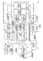
- Memory 11 comprises two parts, a master note local memory lla and a composite master note memory llb.
- the memory 11 stores permanent data which is used in the cross-correlation process to be described hereinafter and the plurality of constants from which the constants are selected to solve the Taylor series hereinafter referred to as the polynomial equation for each reference patch value of the synthetic master note.
- the master note patch memory lla contains three intaglio areas and three lithographic areas inserted therein by the high resolution scanning of a flawless master note whose intaglio and lithographic images are in nominal, i.e., perfect registration.
- the composite master note memory llb stores a plurality of previously calculated constants in sets associated with a reference point.
- the foregoing data is permanently stored in memory 11 and is changed only for the type, e.g., denomination or nationality of the notes to be inspected and changed.
- a transport system 12 transports sheets each containing, e.g., three notes 13 across and six notes along its length in the direction of the arrow past two registration scanners 14 and a quality inspection scanner 15. While the present invention is capable of inspecting three notes at a time, discussion herein is confined to the inspection of a single note.
- the registration scanners 14 and inspection scanner 15 are solid state, charge-coupled device line array cameras.
- The.registration scanners 14 images picture elements, i. e ., pixels at high resolution, e.g., 0.1 mm x 0.1 mm. These scanners scan along spaced separate paths and provide precise data regarding the intaglio and lithographic images of the particular note being examined.
- the inspection scanner 15 is identical to the registration scanner 14 except that it is of lower resolution on the order of 1 mm x 1 mm pixels which are the size of the test patch values selected for comparison with equal size reference patch values.
- the outputs of the registration scanners 14 are connected to correlators 18 and 19 which also receive inputs from master note patch memory lla.
- Each note 13 on a sheet has fiducial marks representative of the registration of intaglio and lithographic images. However, these give only a rough fix which is used to assure the shifted test note data grid is entirely within the reference note data grid when the images are registered. This condition is illustrated in Figure 2 in which the registration point is ( Xo + 5, y o + n) and the shifted test note data grid (indicated by the dashed area) does not extend beyond the reference note data grid.
- the intaglio and lithographic images are each separately cross correlated with corresponding patches stored in the master note patch memory lla.
- the registration scanner 14 selects three intaglio areas on the test note 13 which corresponds to the three intaglio areas stored in master note patch memory lla and provide them as inputs to correlator 18. Three lithographic areas are also selected from the test note 13 which correspond to the three lithographic areas stored in master note local memory lla and provides them as inputs to correlator 19. Selection of test note data grids (an array of.contiguous pixels on the test note) that fall within the acquisition range of the cross correlator is assured through use of the fiducials. The fiducials are imprinted by the same plates which imprint the note images. Hence once the fiducials are located the intaglio and litho images are also located to the accuracy at the relative position between fiducials and note images.
- Correlator 18 cross correlates each of the three intaglio areas acquired from the test note 13 with their corresponding intaglio areas from master note patch memory lla and provides as outputs a pair of coordinates for each of the three correlations. These three sets of coordinates give the exact location of the centroids of each test note intaglio area with respect to the centroids of the intaglio area stored in master patch note memory lla and, therefore, with respect to the synthetic master memory.
- correlator 19 cross correlates each of the three lithographic areas acquired from the test note 13 with their corresponding lithographic areas from master note local memory lla and provides as outputs a pair of coordinates for each of the three correlations.
- These three sets of coordinates give the exact location of the centroids of each test note lihographic area with respect to the centroids of the lithographic areas stored in master patch note memory lla and, therefore, with respect to the synthetic master memory lla.
- Fig. 2 graphically illustrates the computation of a point of the cross-correlation function.
- the cross-correlation function solves a double summation equation of the form:
- the Reference Note Data grid represents either an intaglio or lithographic area from master note local memory lla.
- the Test Note Data Grid represents the corresponding test area obtained from correlators 18 or 19.
- the Reference Note Data grid is chosen to be larger than the Test Note Data grid so that the Test Note Data grid will always be acquired within the borders of the Reference Note Data grid and may be shifted by increments therein.
- the Reference Note Data grid was chosen as 48 x 48 pixels with the Test Note Data grid chosen to be 32 x 32 pixels.
- a first value of the function is obtained by overlaying the centroids of both images, multiplying all corresponding points and adding the products. To obtain ⁇ ( ⁇ ,yl), the Test Note Grid is shifted as shown by the dashed line in Fig. 2 and the process is repeated for every possible position of the Test Note Data grid within the Reference Note Data grid.
- the largest number obtained by this method identifies the coordinates of the registration point. This is done for each intaglio area and lithographic area and provides three pairs of coordinates to the intaglio coefficient processor 20 and three pairs of coordinates to the lithographic coefficient processor 21. The six sets of coordinates are used to spatially correct for test note rotation and distortion.
- the processors 20 and 21 receive these intaglio and lithographic coordinates or fixes as inputs, respectively. Each of processors 20 and 21 generates six transformation constants which are used to determine for any given point on the test note where that point falls on the master note.
- Processor 20 which receives the three sets of intaglio image coordinates from correlator 18 computes the six intaglio transformation constants.
- Processor 21 which receives the three sets of lithographic image coordinates from correlator 19 computes the six lithographic constants. These constants are computed for each test note scanned and, as aforesaid, are used to determine any point on the test note relative to the hypothetical master note. The latter type of computation is a form of image rectification whereby an image A of a given scene is transformed into an image B of the same scene.
- Digital image rectification is the process of mapping pixel intensities from an input image to an output rectified plane.
- This mapping is a bivariate coordinate transformation that takes into account all modelable distortions between the . two images.
- the general form of a polynomial transformation between the two images is: where:
- intaglio coefficient processor 20 The intaglio constants are determined in intaglio coefficient processor 20 from two sets of three simultaneous equations in three unknowns by substituting the fix data from correlator 18 into equations 3 and 4 above.
- the six resulting equations are:
- the six lithographic constants a , a 1 , a 2 , b 0 , b 1 and b 2 are determined in the litho coefficient processor 21 by solving the above equations using the three litho fixes obtained from litho correlator 19.
- This calculation is performed in processors 22 and 23, respectively, for each patch on the test note as seen by inspection scanner 15 to formulate therein the address of the fifteen constants in memory needed to compute a reference patch value corresponding to a particular test patch.
- Processors 22 and 23 receive the six intaglio constants and six lithographic constants, respectively.
- processors 22 and 23 receive inputs (u, v) from inspection scanner 15 indicative of which test patch of a line of test patches are being scanned to insure that the particular reference patch address to be generated corresponds to the appropriate test patch being scanned.
- the test patch values in a scan line which is the mode in which inspection scanner sees them may be stored in a buffer and clocked out for comparison with the appropriate reference patch.
- synchronization of the test patch with the appropriate reference patch is accomplished by the input from inspection scanner 15 to processor 22 and 23 by detection by the inspection scanner 15 of the intaglio and lithographic fiducials associated with each test note.
- This provides the coordinates, e.g., the scan line (u) and patch number (v) within a scan line to the processors 22 and 23.
- This enables intaglio transformation processor 22 to compute the coordinates (x,y ) on the synthetic master note of the intaglio image on the test patch under inspection. It also enables litho transformation processor 23 to compute the coordinates ( X 1 , y l ) of the litho image on the test patch under inspection.
- the address of the 15 constants required from memory and the variables in the Taylor series expansion equations are determined in the Address/Delta Variable Processor 24 as described below for the condition in which the image misregistration is small.
- the address of the constants consists of two coordinates, an X and a y component. Both components are determined in a similar manner.
- We typically illustrate the technique by considering the component of the address assuming 16 bit processors are used to perform the digital computations.
- the output of intaglio transformation processor 22 will be a 16 bit binary word.
- the scaling in the system would be adjusted so that one of the bits in this 16 bit word has the units of the center to center spacing of the reference points in the synthetic master memory. Assuming the center to center spacing is 0.5 mm (as appears reasonable based upon work on specific currencies investigated), the significance of each bit in the digital work representing X in the output of processor 22 would be made to be as shown below by proper scaling.
- bit number 7 in X when bit number 7 in X changes it corresponds to a change in the position of the test patch equal to the center to center spacing of the reference points in synthetic master note memory, i.e., .5 mm.
- bit number seven represents 0.5 mm
- the word for 0.25 mm has a 1 in bit position six and zeros everywhere else.
- the X component of the address of the constants for the test patch under inspection is obtained from bits 7 to 16 of X + 1/2 C as shown below:
- the X variable (Delta X) in the Taylor series expansion is given by: It may be noted this yields a variable having a maximum of 6 bits plus sign.
- Figure 3 is a graphic illustration of the method of determining the address of the 15 constants in the synthetic master note memory.
- the intaglio . transformation has located P li as the point on the master note corresponding to the centroid of the intaglio on the ith test note patch.
- the litho transformation has located P Li as the point on the master note corresponding to the centroid of the litho on the ith test note patch.
- P Ii falls within the region ABCD which determines maximum values of ⁇ X, ⁇ Y with respect to reference point X r , Y r .
- the first pair of coordinates of the r r master memory address are X r , Y r and ⁇ X ⁇ Y are the X and Y components of the vector ⁇ TI .
- P Li falls within the region ABCD which it is assumed also determines the maximum value of ⁇ X 1 , ⁇ Y 1 with respect to reference point X r , Y r .
- the second pair of coordinates of the master memory address is X r , Y (equal to the first pair) and 4 X 1 , ⁇ Y 1 are the X and Y components of the vector ⁇ TL .
- the image misregistration on the ith patch is the vector ⁇ IL which has terminal points on P Ii and PLi.
- Processor 25 performs the solution of the series approximation polynomial utilizing the four variables ⁇ x , ⁇ y, ⁇ X 1, ⁇ y 1 provided by processor 24. Processor 25 also receives the fifteen constants necessary for the solution of the polynomial from composite master note memory llb which has been accessed by the address formulated in processor 24 and brought out to processor 25.
- the solution of the series approximation polynomial is done for each reference patch value on the test note under inspection of which there are approximately 12,000 in a typical currency note with each patch being 1 mm by 1 mm.
- the polynomial is solved 12,000 times.
- Each solution generates one reference patch value which is ideally equal to the reflectance of the test patch value under inspection integrated over its area, i.e., 1 mm by 1 mm.
- Each reference patch value thus generated represents a flawless patch of the hypothetical master note having the same misregistration between the intaglio and lithographic as the test note scanned. Notes that are misregistered beyond the tolerance of ⁇ 2 mm are rejected by thresholding X 1 - X and Y 1 - Y at 2 mm and using the resulting exceedance to reject the note.
- Each reference patch value generated i.e., each solution of the series approximation polynomial is provided as an input to exceedance detector 26 which also receives inputs representative of each test patch value in each scan line from inspection scanner 15. Since the misregistration between the intaglio and lithographic images of the generated hypothetical master note has been constrained to be equal to that of each test note inspected the problem of flaw inspection reduces to that used in the inspection of single image test notes, e.g., United States currency where a stored master note is compared to the test note,
- Accept/reject decisions are made in flaw detector 27.
- Data inputs to flaw detector 27 are E 1 . E 2 , E 3 .
- Programmable constant inputs are flaw cluster parameters Q 1 . Q 2 , and Q 3 .
- Accept/reject decisions are made in accordance with the following alogrithms, all of which operate in parallel, i.e., reject decision on any algorithm cause the note to be rejected.
- the numbers Q 1 , Q 2 and Q 3 are monatonially increasing positve integer numbers (e.g.
- the first of the above algorithms is aimed at finding defects which show up on a single patch
- the second is aimed at finding defects which show up on a small cluster of patches (not necessarily contiguous)
- the third algorithm is aimed at finding defects which show up on a relatively huge cluster of patches.
- Flaws are most likely to be detected by the algorithm designed to detect them. Three algorighms have been found to be an optimum number for the type of flaws occuring on U.S. Currency. However, other currencies may require a different number of algorithms. Notes rejected by any one of the above algorithms are identified such as by marking.
- Step 1 is to generate a description of the function as a set of.numbers which give the value of the function at equally spaced increments in each of the 4 variables ( ⁇ x , ⁇ Y, ⁇ X, ⁇ Y 1 ). This can be done for example by making measurements on a set of notes having equally spaced increments of image misregistration. Other more practical methods of achieving the same result are also available.
- Each of the 15 constants in the quadratic polynomial is as the sum of products of each of the data points in the numerical description of the function and a set of constant multiples referred to as convolutes.
- the mathematical process by which the constants are determined is referred to as convolution.
- the convolutes are determined to satisfy some "goodness" of fit such as minimum squared difference between the points determined from the analytic equation and the corresponding data points.
- the number of convolutes will always be equal to the number of data points in the data set which describes the function.
- the coefficients of the variables in the Taylor series expansion are the same as the coefficients of the same variables in the quadratic polynomial.
- the constant terms are almost but not exactly equal. In general, the difference between the two approximation equations is negligible.
- the set of 15 constants is retrieved by computing the centroid of the approximation range and using that data to determine the address at the 15 constants as previously described.
- each test note is scanned an address is formulated to bring out from memory the fifteen constants which together with the four variables permit the solution of the series approximation polynominal to give a reference patch value for each test patch value of a test note scanned.
- Each reference patch value is the representation of a perfect reference patch value modified to accommodate for the image misregistration of the test note. After all of the reference patch values are compared to their corresponding test patch value, the note is adjudged acceptable or not.
- a typical sheet on a web press consists of 6 rows of notes with each row having 3 notes so that a sheet consists of 6 rows and 3 columns.
- the registration and inspection scanners must be synchronized to sheet position within the acquisition range of the registration scanner (about ⁇ 0.5 mm). These functions are provided by the sheet position encoder 17 and controller 16.
- the sheet position encoder senses sheet position by detecting fiducial marks printed on the sheet for the purpose of enabling approximate sheet position to be easily sensed. Alignment between sheet position encoder, registration scanner, and inspection scanner is established during fabrication of the equipment.
Landscapes
- Health & Medical Sciences (AREA)
- General Health & Medical Sciences (AREA)
- Toxicology (AREA)
- Physics & Mathematics (AREA)
- General Physics & Mathematics (AREA)
- Investigating Materials By The Use Of Optical Means Adapted For Particular Applications (AREA)
- Inspection Of Paper Currency And Valuable Securities (AREA)
- Image Analysis (AREA)
- Image Processing (AREA)
Applications Claiming Priority (2)
| Application Number | Priority Date | Filing Date | Title |
|---|---|---|---|
| US06/340,138 US4482971A (en) | 1982-01-18 | 1982-01-18 | World wide currency inspection |
| US340138 | 1982-01-18 |
Publications (3)
| Publication Number | Publication Date |
|---|---|
| EP0084137A2 true EP0084137A2 (fr) | 1983-07-27 |
| EP0084137A3 EP0084137A3 (en) | 1984-01-11 |
| EP0084137B1 EP0084137B1 (fr) | 1987-11-11 |
Family
ID=23332048
Family Applications (1)
| Application Number | Title | Priority Date | Filing Date |
|---|---|---|---|
| EP82111719A Expired EP0084137B1 (fr) | 1982-01-18 | 1982-12-17 | Vérification de notes bancaires |
Country Status (4)
| Country | Link |
|---|---|
| US (1) | US4482971A (fr) |
| EP (1) | EP0084137B1 (fr) |
| JP (1) | JPS58125181A (fr) |
| DE (1) | DE3277652D1 (fr) |
Cited By (5)
| Publication number | Priority date | Publication date | Assignee | Title |
|---|---|---|---|---|
| WO1992014221A1 (fr) * | 1991-02-08 | 1992-08-20 | De La Rue Giori S.A. | Installation de controle |
| EP0477711A3 (en) * | 1990-09-27 | 1993-05-12 | Oki Electric Industry Company, Limited | Bill examination device |
| GB2264779A (en) * | 1992-02-20 | 1993-09-08 | Thermoteknix Systems Ltd | Monitoring changes in image characteristics. |
| US5503262A (en) * | 1992-03-10 | 1996-04-02 | Mars Incorporated | Apparatus for the classification of a pattern for example on a banknote or a coin |
| EP0742538A3 (fr) * | 1992-11-30 | 1998-10-07 | Mars Incorporated | Procédé et appareil de tri d'un article |
Families Citing this family (18)
| Publication number | Priority date | Publication date | Assignee | Title |
|---|---|---|---|---|
| EP0186874B1 (fr) * | 1984-12-26 | 1994-06-08 | Hitachi, Ltd. | Procédé et appareil pour vérifier la géométrie des motifs multicouches pour des structures de circuits intégrés |
| JPH01233593A (ja) * | 1988-03-14 | 1989-09-19 | Fujitsu Ltd | 移動原点推定方式および移動原点推定方式を用いた紙葉鑑別システム |
| JP2546876B2 (ja) * | 1988-03-14 | 1996-10-23 | 富士通株式会社 | ディジタル線分作成方法及び紙葉類鑑別システム |
| JPH01233592A (ja) * | 1988-03-14 | 1989-09-19 | Fujitsu Ltd | 移動原点選択方式および移動原点選択方式を用いた紙葉類鑑別システム |
| US5046111A (en) * | 1989-02-09 | 1991-09-03 | Philip Morris Incorporated | Methods and apparatus for optically determining the acceptability of products |
| US5146510A (en) * | 1989-02-09 | 1992-09-08 | Philip Morris Incorporated | Methods and apparatus for optically determining the acceptability of products |
| US5237621A (en) * | 1991-08-08 | 1993-08-17 | Philip Morris Incorporated | Product appearance inspection methods and apparatus employing low variance filter |
| CA2226473A1 (fr) * | 1995-06-07 | 1996-12-19 | Pressco Technology, Inc. | Systeme d'inspection des surfaces exterieures d'objets |
| US6044915A (en) * | 1995-07-11 | 2000-04-04 | Case Corporation | Hitch rocker for a work vehicle |
| US6018687A (en) * | 1997-02-07 | 2000-01-25 | Quad/Tech, Inc. | Method and apparatus for printing cutoff control using prepress data |
| US6748112B1 (en) * | 1998-07-28 | 2004-06-08 | General Electric Company | Method and apparatus for finding shape deformations in objects having smooth surfaces |
| US6580820B1 (en) * | 1999-06-09 | 2003-06-17 | Xerox Corporation | Digital imaging method and apparatus for detection of document security marks |
| US6539391B1 (en) * | 1999-08-13 | 2003-03-25 | At&T Corp. | Method and system for squashing a large data set |
| JP2001155172A (ja) * | 1999-11-29 | 2001-06-08 | Seiko Epson Corp | 長さ演算判別手段、角度演算判別手段及び画像判別システム |
| AT412593B (de) * | 2003-03-31 | 2005-04-25 | Oebs Gmbh | Verfahren zum kalibrieren |
| US7327857B2 (en) * | 2004-03-09 | 2008-02-05 | General Electric Company | Non-contact measurement method and apparatus |
| US20070041628A1 (en) * | 2005-08-17 | 2007-02-22 | Xerox Corporation | Detection of document security marks using run profiles |
| US20080112460A1 (en) | 2006-11-14 | 2008-05-15 | Ncr Corporation | Detecting intaglio print |
Family Cites Families (11)
| Publication number | Priority date | Publication date | Assignee | Title |
|---|---|---|---|---|
| US3496371A (en) * | 1966-05-26 | 1970-02-17 | Mitsubishi Heavy Ind Ltd | Apparatus for comparing sample document to standard including correlation |
| GB1234941A (en) * | 1967-08-16 | 1971-06-09 | Emi Ltd | Improvements in or relating to pattern recognition devices |
| US3748644A (en) * | 1969-12-31 | 1973-07-24 | Westinghouse Electric Corp | Automatic registration of points in two separate images |
| CH609795A5 (fr) * | 1976-04-30 | 1979-03-15 | Gretag Ag | |
| US4143279A (en) * | 1976-04-30 | 1979-03-06 | Gretag Aktiengesellschaft | Method and apparatus for testing the print quality of printed texts, more particularly banknotes |
| JPS5358297A (en) * | 1976-11-06 | 1978-05-26 | Fuji Electric Co Ltd | Timing pulse generator of banknote examining apparatus |
| GB1575607A (en) * | 1977-03-02 | 1980-09-24 | Planer Ltd G | Quality control |
| US4197584A (en) * | 1978-10-23 | 1980-04-08 | The Perkin-Elmer Corporation | Optical inspection system for printing flaw detection |
| US4288781A (en) * | 1978-11-13 | 1981-09-08 | The Perkin-Elmer Corporation | Currency discriminator |
| US4311914A (en) * | 1978-12-18 | 1982-01-19 | Gretag Aktiengesellschaft | Process for assessing the quality of a printed product |
| JPS56149687A (en) * | 1980-04-22 | 1981-11-19 | Tokyo Shibaura Electric Co | Printed end detector |
-
1982
- 1982-01-18 US US06/340,138 patent/US4482971A/en not_active Expired - Lifetime
- 1982-12-17 EP EP82111719A patent/EP0084137B1/fr not_active Expired
- 1982-12-17 DE DE8282111719T patent/DE3277652D1/de not_active Expired
-
1983
- 1983-01-18 JP JP58005376A patent/JPS58125181A/ja active Pending
Cited By (8)
| Publication number | Priority date | Publication date | Assignee | Title |
|---|---|---|---|---|
| EP0477711A3 (en) * | 1990-09-27 | 1993-05-12 | Oki Electric Industry Company, Limited | Bill examination device |
| WO1992014221A1 (fr) * | 1991-02-08 | 1992-08-20 | De La Rue Giori S.A. | Installation de controle |
| GB2264779A (en) * | 1992-02-20 | 1993-09-08 | Thermoteknix Systems Ltd | Monitoring changes in image characteristics. |
| GB2264779B (en) * | 1992-02-20 | 1996-05-01 | Thermoteknix Systems Ltd | Monitoring changes in image characteristics |
| US5503262A (en) * | 1992-03-10 | 1996-04-02 | Mars Incorporated | Apparatus for the classification of a pattern for example on a banknote or a coin |
| US5522491A (en) * | 1992-03-10 | 1996-06-04 | Mars Incorporated | Method for the classification of a pattern, for example on a banknote or a coin |
| EP0742538A3 (fr) * | 1992-11-30 | 1998-10-07 | Mars Incorporated | Procédé et appareil de tri d'un article |
| EP0737946A3 (fr) * | 1992-11-30 | 1998-10-07 | Mars Incorporated | Procédé et appareil de tri d'un article |
Also Published As
| Publication number | Publication date |
|---|---|
| US4482971A (en) | 1984-11-13 |
| EP0084137B1 (fr) | 1987-11-11 |
| EP0084137A3 (en) | 1984-01-11 |
| JPS58125181A (ja) | 1983-07-26 |
| DE3277652D1 (en) | 1987-12-17 |
Similar Documents
| Publication | Publication Date | Title |
|---|---|---|
| EP0084137B1 (fr) | Vérification de notes bancaires | |
| EP0582548B2 (fr) | Méthode et appareil pour déterminer un erreur de concordance | |
| US4311914A (en) | Process for assessing the quality of a printed product | |
| KR100954703B1 (ko) | 결함을 검출하는 방법 및 시스템 | |
| US4776023A (en) | Pattern inspection method | |
| US6266437B1 (en) | Sequential detection of web defects | |
| US4131879A (en) | Method and apparatus for determining the relative positions of corresponding points or zones of a sample and an orginal | |
| US6072897A (en) | Dimension error detection in object | |
| US5060276A (en) | Technique for object orientation detection using a feed-forward neural network | |
| EP0206712A2 (fr) | Système de correction d'erreurs d'enregistrement et d'alignement | |
| EP0755024B1 (fr) | Méthode de mise en correspondance d'images | |
| US5818443A (en) | Single step coarse registration and inspection of circular objects | |
| AU761615B2 (en) | Automatic inspection of print quality using an elastic model | |
| CA1084166A (fr) | Methode et appareil d'essai de la qualite d'impression de textes imprimes, notamment de billets de banque | |
| US5912988A (en) | Image processing method and apparatus for distortion compensation | |
| KR20010040998A (ko) | 입체 영상에 의한 자동 검사 시스템 및 그 검사 방법 | |
| US5872871A (en) | Method and device for measuring the position of a pattern | |
| JPH1166381A (ja) | 有価あるいは保証用の物品、特に銀行券を照査するための方法および装置 | |
| CA2171891C (fr) | Methode d'evaluation automatique utilisant un dispositif opto-electronique | |
| JP4121605B2 (ja) | 撮像画像複合歪み検出装置 | |
| JP4220061B2 (ja) | 周期性パターンの欠陥検査方法及び装置 | |
| EP0391587A2 (fr) | Méthode et dispositif pour générer rapidement des coefficients de déformation | |
| JP2003098117A (ja) | 画像の欠陥検出装置及びその欠陥検出方法 | |
| JPH1097623A (ja) | 画像検査方法および装置 | |
| EP0473141A2 (fr) | Procédé pour découvrir une qualité inférieure de données d'images |
Legal Events
| Date | Code | Title | Description |
|---|---|---|---|
| PUAI | Public reference made under article 153(3) epc to a published international application that has entered the european phase |
Free format text: ORIGINAL CODE: 0009012 |
|
| AK | Designated contracting states |
Designated state(s): CH DE FR GB IT LI |
|
| PUAL | Search report despatched |
Free format text: ORIGINAL CODE: 0009013 |
|
| AK | Designated contracting states |
Designated state(s): CH DE FR GB IT LI |
|
| 17P | Request for examination filed |
Effective date: 19840710 |
|
| GRAA | (expected) grant |
Free format text: ORIGINAL CODE: 0009210 |
|
| AK | Designated contracting states |
Kind code of ref document: B1 Designated state(s): CH DE FR GB IT LI |
|
| REF | Corresponds to: |
Ref document number: 3277652 Country of ref document: DE Date of ref document: 19871217 |
|
| ITF | It: translation for a ep patent filed | ||
| ET | Fr: translation filed | ||
| PLBE | No opposition filed within time limit |
Free format text: ORIGINAL CODE: 0009261 |
|
| STAA | Information on the status of an ep patent application or granted ep patent |
Free format text: STATUS: NO OPPOSITION FILED WITHIN TIME LIMIT |
|
| 26N | No opposition filed | ||
| PGFP | Annual fee paid to national office [announced via postgrant information from national office to epo] |
Ref country code: FR Payment date: 19911107 Year of fee payment: 10 |
|
| PGFP | Annual fee paid to national office [announced via postgrant information from national office to epo] |
Ref country code: GB Payment date: 19911114 Year of fee payment: 10 |
|
| PGFP | Annual fee paid to national office [announced via postgrant information from national office to epo] |
Ref country code: DE Payment date: 19911121 Year of fee payment: 10 Ref country code: CH Payment date: 19911121 Year of fee payment: 10 |
|
| ITTA | It: last paid annual fee | ||
| PG25 | Lapsed in a contracting state [announced via postgrant information from national office to epo] |
Ref country code: GB Effective date: 19921217 |
|
| PG25 | Lapsed in a contracting state [announced via postgrant information from national office to epo] |
Ref country code: LI Effective date: 19921231 Ref country code: CH Effective date: 19921231 |
|
| GBPC | Gb: european patent ceased through non-payment of renewal fee |
Effective date: 19921217 |
|
| PG25 | Lapsed in a contracting state [announced via postgrant information from national office to epo] |
Ref country code: FR Effective date: 19930831 |
|
| REG | Reference to a national code |
Ref country code: CH Ref legal event code: PL |
|
| PG25 | Lapsed in a contracting state [announced via postgrant information from national office to epo] |
Ref country code: DE Effective date: 19930901 |
|
| REG | Reference to a national code |
Ref country code: FR Ref legal event code: ST |