EP0084202B1 - Vorrichtung zum intermittierenden Antrieb des Endlosbandes in eine automatische Siebdruckmaschine - Google Patents
Vorrichtung zum intermittierenden Antrieb des Endlosbandes in eine automatische Siebdruckmaschine Download PDFInfo
- Publication number
- EP0084202B1 EP0084202B1 EP19820300217 EP82300217A EP0084202B1 EP 0084202 B1 EP0084202 B1 EP 0084202B1 EP 19820300217 EP19820300217 EP 19820300217 EP 82300217 A EP82300217 A EP 82300217A EP 0084202 B1 EP0084202 B1 EP 0084202B1
- Authority
- EP
- European Patent Office
- Prior art keywords
- pulse number
- endless belt
- electric motor
- pulse
- feed
- Prior art date
- Legal status (The legal status is an assumption and is not a legal conclusion. Google has not performed a legal analysis and makes no representation as to the accuracy of the status listed.)
- Expired
Links
- 238000007650 screen-printing Methods 0.000 title claims description 6
- 230000007246 mechanism Effects 0.000 claims description 27
- 238000010586 diagram Methods 0.000 description 8
- 239000004744 fabric Substances 0.000 description 6
- 238000007639 printing Methods 0.000 description 6
- PCTMTFRHKVHKIS-BMFZQQSSSA-N (1s,3r,4e,6e,8e,10e,12e,14e,16e,18s,19r,20r,21s,25r,27r,30r,31r,33s,35r,37s,38r)-3-[(2r,3s,4s,5s,6r)-4-amino-3,5-dihydroxy-6-methyloxan-2-yl]oxy-19,25,27,30,31,33,35,37-octahydroxy-18,20,21-trimethyl-23-oxo-22,39-dioxabicyclo[33.3.1]nonatriaconta-4,6,8,10 Chemical compound C1C=C2C[C@@H](OS(O)(=O)=O)CC[C@]2(C)[C@@H]2[C@@H]1[C@@H]1CC[C@H]([C@H](C)CCCC(C)C)[C@@]1(C)CC2.O[C@H]1[C@@H](N)[C@H](O)[C@@H](C)O[C@H]1O[C@H]1/C=C/C=C/C=C/C=C/C=C/C=C/C=C/[C@H](C)[C@@H](O)[C@@H](C)[C@H](C)OC(=O)C[C@H](O)C[C@H](O)CC[C@@H](O)[C@H](O)C[C@H](O)C[C@](O)(C[C@H](O)[C@H]2C(O)=O)O[C@H]2C1 PCTMTFRHKVHKIS-BMFZQQSSSA-N 0.000 description 3
- 238000001514 detection method Methods 0.000 description 3
- 230000002159 abnormal effect Effects 0.000 description 2
- 238000006243 chemical reaction Methods 0.000 description 2
- 230000008602 contraction Effects 0.000 description 2
- 238000007796 conventional method Methods 0.000 description 2
- 238000006073 displacement reaction Methods 0.000 description 2
- 230000001133 acceleration Effects 0.000 description 1
- 239000003086 colorant Substances 0.000 description 1
- 230000003247 decreasing effect Effects 0.000 description 1
- 238000001035 drying Methods 0.000 description 1
- 230000000694 effects Effects 0.000 description 1
- 230000000977 initiatory effect Effects 0.000 description 1
- 230000010354 integration Effects 0.000 description 1
- 238000000034 method Methods 0.000 description 1
- 230000002035 prolonged effect Effects 0.000 description 1
- 238000005406 washing Methods 0.000 description 1
- XLYOFNOQVPJJNP-UHFFFAOYSA-N water Substances O XLYOFNOQVPJJNP-UHFFFAOYSA-N 0.000 description 1
Images

Classifications
-
- B—PERFORMING OPERATIONS; TRANSPORTING
- B41—PRINTING; LINING MACHINES; TYPEWRITERS; STAMPS
- B41F—PRINTING MACHINES OR PRESSES
- B41F15/00—Screen printers
- B41F15/08—Machines
- B41F15/10—Machines for multicolour printing
-
- B—PERFORMING OPERATIONS; TRANSPORTING
- B41—PRINTING; LINING MACHINES; TYPEWRITERS; STAMPS
- B41F—PRINTING MACHINES OR PRESSES
- B41F15/00—Screen printers
- B41F15/08—Machines
- B41F15/0831—Machines for printing webs
- B41F15/0845—Machines for printing webs with flat screens
- B41F15/085—Machines for printing webs with flat screens with a stationary screen and a moving squeegee
Definitions
- the present invention relates to an apparatus for intermittently driving an endless belt in an automatic screen printing machine. More particularly, the present invention relates to an apparatus for intermittently driving an endless belt in an automatic screen printing machine, in which the precision of feeding of the endless belt is enhanced irrespectively of non-uniform mechanical properties of the endless belt which are due to the uneven thickness and other factors.
- an apparatus comprising a direct current electric motor for intermittently driving an endless belt, a switch for setting a repeat length of the endless belt while converting it to a pulse number, a pulse generator for detecting as a pulse number the actual feed length of the endless belt according to displacement of the endless belt, a digital display device for displaying the repeat length detected by said detecting mechanism in the form of a numerical figure, a digital control mechanism for generating a starting signal, an acceleration signal, a constant speed signal or a speed reduction and stop signal according to the pulse number set by said switch and an electric motor control mechanism for controlling an input to said direct current electric motor according to the signal from the digital control mechanism to start the electric motor, accelerate the electric motor, drive the electric motor at a constant speed or decelerate and stop the electric motor, wherein said digital control mechanism comprises a computing mechanism for subtracting the detected pulse number from the set pulse number and generating a speed reduction signal so that the endless belt is stopped at a
- the mechanical feed precision is excellent.
- a feed error due to the endless belt per se is unavoidable because the endless belt is ordinarily composed of a reinforced rubber or the like and is not a rigid member.
- This feed error of the endless belt is due to non-uniform mechanical properties owing to the uneven thickness and other factors. Especially in case of intermittent feeding, the feed error is caused by the difference of the quantity of elongation at the respective starting times and the difference of the degree of contraction at the respective stopping times. Furthermore, in the case where there are two supporting rollers, only the pulling roller is driven to start the endless belt as a whole at a stroke from the stopped state as in conventional techniques, the tension is concentrated on the pulling side of the endless belt, which is another cause of occurrence of the feed error of the endless belt.
- an apparatus for intermittently driving an endless belt in an automatic screen printing machine which comprises a pair of rollers, an endless belt supported on the rollers, a direct current electric motor for intermittently driving said rollers and a motor control system for controlling the rotation of the motor by setting a pulse number representing a desired repeat length of the movement of the endless belt, detecting the actual feed length of the endless belt as a pulse number and subtracting the detected pulse number from the set pulse number to stop the motor and thereby the movement of the endless belt at the repeat length corresponding to the set pulse number, characterised in that each of the pulling and feed-out rollers supporting the endless belt is provided with a direct current electric motor capable of independently driving the respective roller, each motor having associated therewith a respective pulse generator for detecting a pulse number representing the actual rotation of the associated roller and a digital servo mechanism for substracting the detected pulse number from the set pulse number and reducing the speed of the associated motor and stopping the same to stop the belt after movement thereof through the repeat length corresponding to the set pulse number, characterised in that each of the pulling
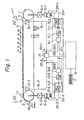
- an endless belt 3 is laid out and supported between a pair of rollers, that is, a pulling roller 1 and feed-out roller 2, and this endless belt is intermittently fed by a repeat length P and a cloth 20 to be printed, which is placed on the belt 3, is printed through a scrren 4 by known printing means.
- a pasting device 16 is arranged in the vicinity of the feed-out roller 2 to apply a printing paste to the belt 3 and a pasting press roller 17 is arranged above the feed-out roller 2 so that the endless belt 3 is gripped between the rollers 2 and 17.
- the cloth 20 to be printed is fed between the press roller 17 and the belt 3 and is pasted on the belt 3.
- the endless belt 3 is intermittently fed by a predetermined repeat length.
- the screen 4 arranged above the upper running passage of the belt 3 is brought down onto the cloth 20 to be printed, and a squeegee (not shown) is scanned and moved to apply a color paste on the screen 4 to the cloth 20.
- the screen 4 is elevated, and this cycle is repeated at a frequency corresponding to the number of colors to be printed on the cloth 20 and the printing operation is completed.
- the printed cloth 20' is separated from the endless belt 3 and fed to the subsequent step, for example, the drying step.
- the endless belt 3 is washed by a washing device 18 arranged along the lower running passage of the belt 3, and water is removed from the endless belt 3 by a water-removing device (mangle) 17. The above procedures are repeated.
- a roller-driving direct current electric motor 5-1 is mounted for the pulling roller 1, if necessary, through a reduction gear 6-1, and a roller-driving direct current electric motor 5-2 is mounted for the feed-out roller 2, if necessary, through a reduction gear 6-2.
- Pulse generators 12-1 and 12-2 are arranged for the driving rollers 1 and 2, respectively, to detect the actual feed length of the endless belt 3 on both the pulling and feed-out roller sides according to displacements of the rollers 1 and 2, so that these pulse generators 12-1 and 12-2 are driven and rotated without any slip through gear mechanisms (not shown) or the like. These pulse generators 12-1 and 12-2 may be connected to the rear portions of the motors.
- a repeat length setting switch 7 for setting and displaying the repeat length of the endless belt and a pulse converting mechanism (sequence computing circuit) 8 for converting the set repeat length to a pulse number.
- Two digital servo mechanisms comprising elements 9-1, 10-1 and 11-1 and 9-2, 10-2 and 11-2, respectively are mounted for the pulling roller 1 and the feedout roller 2, respectively, to subtract the detected pulse numbers supplied from the pulse generators 12-1 and 12-2 from the set pulse number supplied from the mechanism 8 and stop the direct current electric motors 5-1 and 5-2 so as to stop the belt 3 at the repeat length corresponding to the set pulse number.
- Each of the servo mechanisms comprises a deviation counter 9-1, (9-2), a digital/analog converter 10-1, (10-2) and an electric motor control mechanism 11-1, (11-2).
- the set pulse number from the pulse converting mechanism 8 is fed to the deviation counter 9-1, (9-2) through a line 21-1, (21-2) and the detected pulse number from the pulse generator 12-1, (12-2) is fed to the deviation counter 9-1, (9-2) through lines 15-1 and 22-1 (15-2 and 22-2), and in the deviation counter 9-1, (9-2), compution of subtracting the detected pulse number from the set pulse number is performed.
- the computed pulse generated from the counter 9-1, (9-2) is converted to a voltage by the digital/analog converter 10-1, (10-2), and this voltage signal is supplied to the electric motor control mechanism 11-1, (11-2) and a predetermined electric input is fed to the direct current electric motor 5-1, (5-2) through a line 23-1, (23-2) to reduce the speed of the motor 5-1, (5-2) and stop the motor 5-1, (5-2) according to the set pulse number.
- a tachometer generator 13-1, (13-2) is attached to the direct current electric motor 5-1, (5-2) to detect the actual rotation speed of the electric motor 5-1, (5-2), and the detection signal of the tachometer generator 13-1, (13-2) is fed back to the electric motor control mechanism 11-1, (11-2) through a line 24-1, (24-2).
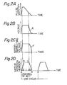
- Figs. 2-A, 2-B, 2-C and 2-D are diagrams illustrating the computed pulse, the voltage generated in the digital/analog converter, the input to the electric motor and the feeding of the belt, respectively.
- the difference between the pulse number L set as the repeat length by the switch 7 and pulse converting mechanism 8 and the detected pulse number R from the pulse generator 12-1, (12-2) is computed by the deviation counter 9-1, (9-2), that is, a computer.
- the computed pulse number (L-R) is abruptly increased with initiation of driving of the electric motor, as shown in Fig. 2-A, and it is then decreased with increase of the rotation time.
- the computed pulse number (L-R) is fed to the digital/analog converter 10-1, (10-2) and is converted to a voltage.
- the maximum value of the voltage is controlled to a certain level, as shown in Fig. 2-B.
- the generated voltage is expressed by an exponential function curve E. Since precise control becomes difficult if the time is prolonged, this curve is converted to a function or integration curve F as shown in Fig. 2-C.
- the rotation of the electric motor that is, the feeding of the belt
- the line A-B-C-D namely, the accelerated driving section AB, the constant speed driving section BC and the decelerated driving section CD.
- the belt-stopping section DA One cycle of the printing operation consists of these sections A-B, B-C, C-D and D-A.
- the area surrounded by the line A-B-C-D corresponds to the feed length of the belt.
- a respective digital servo mechanism, pulse generator and direct current electric motor are provided for each of the pulling roller and the feed-out roller, and the detected pulses from both the pulse generators are compared with each other and the inputs to the direct current motors are controlled according to the difference between the two detected pulses.
- the detected pulse number from the pulse generator 12-2 on the feed-out roller side is directly fed back to the deviation counter 9-2 on the feed-out roller side through the lines 15-2 and 22-2, and simultaneously, the detection signal from the pulse generator 12-2 on the feed-out roller side is supplied to the deviation comparing counter 14 through the lines 15-2 and 25-2 and the detection signal from the pulse generator 12-1 on the pulling roller side is supplied to the deviation comparing counter 14 through the lines 15-1 and 25-1.
- this deviation counter 14 both the detected pulse numbers are compared with each other, and the difference is converted to a correcting voltage and this correcting voltage is supplied to the electric motor control mechanism 11-2 on the feed-out roller side through a line 26.
- the deviation comparing counter 14 compares the pulse number from the pulse generator 12-2 on the feed-out roller side with the pulse number from the pulse generator 12-1 on the pulling roller side, and when the pulse number on the feed-out roller side is different from the pulse number on the pulling roller side, the counter immediately controls the gate signal to the electric motor control mechanism 11-2 on the feed-out roller side, that is, the electric input to the electric motor 5-2 on the feed-out roller side, so that the detected pulse number of the pulse generator 12-1 is made equal to the detected pulse number of the pulse generator 12-2.
- the deviation comparing counter 14 by the deviation comparing counter 14, the difference between the detected pulse number on the feed-out roller side and the detected pulse number on the pulling roller side is detected at every moment and the inputs to the electric motors are corrected so that in Fig. 3, the time-speed diagram ABCD is made equal to the time-speed diagram AB'C'D' with respect to not only the area (feed length) but also the trapezoidal shape.
- the difference of the feed length between the two rollers that is, the difference of area
- the pulse number corresponding to this difference Lx is added to the side of the feed-out roller 2 to effect correction.
- this correction is not performed after the lapse of the time t, but the correction is made at every moment for each pulse.
- the pulling roller 1 and the feed-out roller 2 are driven by different electric motors, the detected pulse numbers are independently subtracted from the set pulse number and the electric motors are stopped at the pulse number corresponding to the set pulse number. Simultaneously, the detected pulse number from the pulling roller is compared with the detected pulse number from the feed-out roller and the inputs to the electric motors are controlled according to the difference between the two detected pulse numbers.
- the pulse number to the repeat length is in the range of from 0.005 mm/pulse to 0.1 mm/pulse, and the precision of comparison and correction attainable in the deviation comparing counter 14 is ⁇ 1 pulse.
- the level of the correcting electric signal from the deviation comparing counter 14 can be freely adjusted by a variable resistor (not shown) according to the capacitance of the electric motor.
- the pulling roller 1 is regarded as the main roller and the feed-out roller 2 is regarded as the subsidiary roller, and driving of the feed-out roller 2 is compared and corrected based on the pulse number generated from the side of the pulling roller 1.
- the above-mentioned characteristic features can similarly be attained even if the reverse structure is adopted.
- the distribution of the capacitance between the direct current electric motors 5-1 and 5-2 is appropriately determined according to the size of the printing machine, that is, the load of the intermittent feeding of the endless belt, and other loads. For example, in the case where 7.5 KW is necessary for driving one roller alone as in the conventional techniques, this may be divided equally so the capacity of 3.7 KW is distributed to each electric motor. Furthermore, it is possible to distribute 5.5 KW to the electric motor on the pulling roller side and 2.2 KWto the electric motor on the feed-out roller side.
- the diameter of the pulling roller 1 should be equal to the diameter of the feed-out roller 2 and the rotation rate and pulse-generating number of the pulse generator 12-1 should be equal to those of the pulse generator 12-2.
- the difference of the processed dimension of the diameter can be adjusted and corrected, for example, by F/F conversion (frequency conversion) in the deviation counters 9-1 and 9-2.
Landscapes
- Engineering & Computer Science (AREA)
- Mechanical Engineering (AREA)
- Screen Printers (AREA)
Claims (2)
Priority Applications (2)
| Application Number | Priority Date | Filing Date | Title |
|---|---|---|---|
| DE8282300217T DE3264803D1 (en) | 1982-01-15 | 1982-01-15 | Apparatus for intermittently driving endless belt in automatic screen printing machine |
| EP19820300217 EP0084202B1 (de) | 1982-01-15 | 1982-01-15 | Vorrichtung zum intermittierenden Antrieb des Endlosbandes in eine automatische Siebdruckmaschine |
Applications Claiming Priority (1)
| Application Number | Priority Date | Filing Date | Title |
|---|---|---|---|
| EP19820300217 EP0084202B1 (de) | 1982-01-15 | 1982-01-15 | Vorrichtung zum intermittierenden Antrieb des Endlosbandes in eine automatische Siebdruckmaschine |
Publications (2)
| Publication Number | Publication Date |
|---|---|
| EP0084202A1 EP0084202A1 (de) | 1983-07-27 |
| EP0084202B1 true EP0084202B1 (de) | 1985-07-24 |
Family
ID=8189548
Family Applications (1)
| Application Number | Title | Priority Date | Filing Date |
|---|---|---|---|
| EP19820300217 Expired EP0084202B1 (de) | 1982-01-15 | 1982-01-15 | Vorrichtung zum intermittierenden Antrieb des Endlosbandes in eine automatische Siebdruckmaschine |
Country Status (2)
| Country | Link |
|---|---|
| EP (1) | EP0084202B1 (de) |
| DE (1) | DE3264803D1 (de) |
Families Citing this family (6)
| Publication number | Priority date | Publication date | Assignee | Title |
|---|---|---|---|---|
| GR1000069B (el) * | 1988-02-23 | 1990-10-31 | Ioannis Maniopoulos | Αυτοματη ευθυγραμμη τυπωτικη μηχανη μεταξωτυπιας. |
| US4933613A (en) * | 1988-12-16 | 1990-06-12 | Truth Incorporated | Control for operating a plurality of window operators |
| CN101786370A (zh) * | 2010-01-21 | 2010-07-28 | 昆山雄风彩印有限公司 | 丝网印刷机 |
| CN110434758B (zh) * | 2019-09-07 | 2025-01-07 | 浦江县森信水晶有限公司 | 一种平底钻正反分离设备 |
| CN113548369B (zh) * | 2021-06-21 | 2023-02-17 | 浙江先导热电科技股份有限公司 | 一种间歇式自动上下料装置 |
| CN114162508A (zh) * | 2021-12-31 | 2022-03-11 | 浙江迈睿机器人有限公司 | 具有快速卸货功能的潜伏式仓储搬运机器人 |
Family Cites Families (3)
| Publication number | Priority date | Publication date | Assignee | Title |
|---|---|---|---|---|
| IT1087472B (it) * | 1977-11-07 | 1985-06-04 | Reggiani Spa | Apparecchatura da stampa a cilindri rotanti per stampare specularmente disegni e/o colori uguali sulle opposte facce di un tessuto o simile |
| US4273042A (en) * | 1977-11-26 | 1981-06-16 | Toshin Kogyo Co., Ltd. | Automatic screen printing process and apparatus |
| JPS55133965A (en) * | 1979-04-06 | 1980-10-18 | Toshin Kogyo Kk | Compensating method and device for feeding error of endless belt in automatic screen printing |
-
1982
- 1982-01-15 DE DE8282300217T patent/DE3264803D1/de not_active Expired
- 1982-01-15 EP EP19820300217 patent/EP0084202B1/de not_active Expired
Also Published As
| Publication number | Publication date |
|---|---|
| EP0084202A1 (de) | 1983-07-27 |
| DE3264803D1 (en) | 1985-08-29 |
Similar Documents
| Publication | Publication Date | Title |
|---|---|---|
| US4419613A (en) | Apparatus for intermittently driving endless belt in automatic screen printing machine | |
| US4898094A (en) | Apparatus and method for controlling a plurality of continuous paper printing machines connected to each other | |
| EP0084202B1 (de) | Vorrichtung zum intermittierenden Antrieb des Endlosbandes in eine automatische Siebdruckmaschine | |
| IT8422653A1 (it) | Macchina da stampa flessografica con comando di moto senza ingranaggi | |
| US3452261A (en) | Torque equalizing control arrangement for a series of driven units | |
| NL7906131A (nl) | Werkwijze voor het besturen van een drukinrichting en drukinrichting met individueel bestuurbare drukorganen. | |
| EP0672525B1 (de) | Vorrichtung zum Drucken von Proben | |
| JPS6362393B2 (de) | ||
| GB2150886A (en) | Printing apparatus | |
| US4238999A (en) | Rotary cylindrical screen printing apparatus for specularly printing equal patterns and/or colors onto the opposite faces of fabrics or the like | |
| EP0251448A2 (de) | Bahndruckmaschine für veränderliche Formate | |
| EP1323538B1 (de) | Motorsteuerverfahren und -vorrichtung | |
| JPS6031728B2 (ja) | 自動スクリ−ン捺染機におけるエンドレスベルトの間欠的駆動装置 | |
| US4626188A (en) | Dough-rolling machine | |
| US4273042A (en) | Automatic screen printing process and apparatus | |
| EP1004437B1 (de) | Motorregelungssystem und seine Verwendung in einem Bilderzeugungsapparat | |
| US4573618A (en) | Apparatus for unrolling and spreading rolled cloth | |
| EP0311106B1 (de) | Spinnmaschine | |
| JPH06198854A (ja) | 多数の印刷ユニットを備えた印刷機械の駆動装置 | |
| JP2587096B2 (ja) | エンドレスベルトの間欠的駆動装置 | |
| KR860000863B1 (ko) | 자동스크린 날염기의 벨트의 간헐적 구동장치 | |
| KR860000862B1 (ko) | 자동 스크린 날염기 | |
| EP0102743A2 (de) | Verfahren und Vorrichtung zur Zuführung einer Trägersubstanz in kontinuierlich arbeitenden Mehrfarbendruckmaschinen | |
| CN109822875A (zh) | 一种放膜压合设备的对花系统 | |
| JP2723451B2 (ja) | ワイヤ放電加工装置 |
Legal Events
| Date | Code | Title | Description |
|---|---|---|---|
| PUAI | Public reference made under article 153(3) epc to a published international application that has entered the european phase |
Free format text: ORIGINAL CODE: 0009012 |
|
| 17P | Request for examination filed |
Effective date: 19821120 |
|
| AK | Designated contracting states |
Designated state(s): CH DE FR GB IT LI NL |
|
| ITF | It: translation for a ep patent filed | ||
| GRAA | (expected) grant |
Free format text: ORIGINAL CODE: 0009210 |
|
| AK | Designated contracting states |
Designated state(s): CH DE FR GB IT LI NL |
|
| REF | Corresponds to: |
Ref document number: 3264803 Country of ref document: DE Date of ref document: 19850829 |
|
| ET | Fr: translation filed | ||
| PLBE | No opposition filed within time limit |
Free format text: ORIGINAL CODE: 0009261 |
|
| STAA | Information on the status of an ep patent application or granted ep patent |
Free format text: STATUS: NO OPPOSITION FILED WITHIN TIME LIMIT |
|
| 26N | No opposition filed | ||
| ITTA | It: last paid annual fee | ||
| PGFP | Annual fee paid to national office [announced via postgrant information from national office to epo] |
Ref country code: DE Payment date: 19991231 Year of fee payment: 19 |
|
| PGFP | Annual fee paid to national office [announced via postgrant information from national office to epo] |
Ref country code: CH Payment date: 20000110 Year of fee payment: 19 |
|
| PGFP | Annual fee paid to national office [announced via postgrant information from national office to epo] |
Ref country code: GB Payment date: 20000112 Year of fee payment: 19 Ref country code: FR Payment date: 20000112 Year of fee payment: 19 |
|
| PGFP | Annual fee paid to national office [announced via postgrant information from national office to epo] |
Ref country code: NL Payment date: 20000131 Year of fee payment: 19 |
|
| PG25 | Lapsed in a contracting state [announced via postgrant information from national office to epo] |
Ref country code: GB Free format text: LAPSE BECAUSE OF NON-PAYMENT OF DUE FEES Effective date: 20010115 |
|
| PG25 | Lapsed in a contracting state [announced via postgrant information from national office to epo] |
Ref country code: LI Free format text: LAPSE BECAUSE OF NON-PAYMENT OF DUE FEES Effective date: 20010131 Ref country code: CH Free format text: LAPSE BECAUSE OF NON-PAYMENT OF DUE FEES Effective date: 20010131 |
|
| PG25 | Lapsed in a contracting state [announced via postgrant information from national office to epo] |
Ref country code: NL Free format text: LAPSE BECAUSE OF NON-PAYMENT OF DUE FEES Effective date: 20010801 |
|
| GBPC | Gb: european patent ceased through non-payment of renewal fee |
Effective date: 20010115 |
|
| REG | Reference to a national code |
Ref country code: CH Ref legal event code: PL |
|
| PG25 | Lapsed in a contracting state [announced via postgrant information from national office to epo] |
Ref country code: FR Free format text: LAPSE BECAUSE OF NON-PAYMENT OF DUE FEES Effective date: 20010928 |
|
| NLV4 | Nl: lapsed or anulled due to non-payment of the annual fee |
Effective date: 20010801 |
|
| PG25 | Lapsed in a contracting state [announced via postgrant information from national office to epo] |
Ref country code: DE Free format text: LAPSE BECAUSE OF NON-PAYMENT OF DUE FEES Effective date: 20011101 |
|
| REG | Reference to a national code |
Ref country code: FR Ref legal event code: ST |