EP0084366B2 - Porte pour chambre de four à coke - Google Patents
Porte pour chambre de four à coke Download PDFInfo
- Publication number
- EP0084366B2 EP0084366B2 EP83100326A EP83100326A EP0084366B2 EP 0084366 B2 EP0084366 B2 EP 0084366B2 EP 83100326 A EP83100326 A EP 83100326A EP 83100326 A EP83100326 A EP 83100326A EP 0084366 B2 EP0084366 B2 EP 0084366B2
- Authority
- EP
- European Patent Office
- Prior art keywords
- door
- coke oven
- steel plate
- steel plates
- plug
- Prior art date
- Legal status (The legal status is an assumption and is not a legal conclusion. Google has not performed a legal analysis and makes no representation as to the accuracy of the status listed.)
- Expired
Links
- 239000000571 coke Substances 0.000 title claims description 22
- 229910000831 Steel Inorganic materials 0.000 claims description 49
- 239000010959 steel Substances 0.000 claims description 49
- 238000010438 heat treatment Methods 0.000 description 9
- 238000004939 coking Methods 0.000 description 4
- 238000007789 sealing Methods 0.000 description 4
- 239000004575 stone Substances 0.000 description 4
- 239000011248 coating agent Substances 0.000 description 3
- 238000000576 coating method Methods 0.000 description 3
- XEEYBQQBJWHFJM-UHFFFAOYSA-N Iron Chemical compound [Fe] XEEYBQQBJWHFJM-UHFFFAOYSA-N 0.000 description 2
- 238000010276 construction Methods 0.000 description 2
- 238000010411 cooking Methods 0.000 description 2
- 230000002349 favourable effect Effects 0.000 description 2
- 238000009413 insulation Methods 0.000 description 2
- 239000000463 material Substances 0.000 description 2
- 238000000034 method Methods 0.000 description 2
- 229910001018 Cast iron Inorganic materials 0.000 description 1
- 230000003247 decreasing effect Effects 0.000 description 1
- 230000000694 effects Effects 0.000 description 1
- 239000011810 insulating material Substances 0.000 description 1
- 229910052742 iron Inorganic materials 0.000 description 1
- 239000002184 metal Substances 0.000 description 1
- 229910052751 metal Inorganic materials 0.000 description 1
- 239000011819 refractory material Substances 0.000 description 1
- 230000000284 resting effect Effects 0.000 description 1
- 239000000725 suspension Substances 0.000 description 1
Images

Classifications
-
- C—CHEMISTRY; METALLURGY
- C10—PETROLEUM, GAS OR COKE INDUSTRIES; TECHNICAL GASES CONTAINING CARBON MONOXIDE; FUELS; LUBRICANTS; PEAT
- C10B—DESTRUCTIVE DISTILLATION OF CARBONACEOUS MATERIALS FOR PRODUCTION OF GAS, COKE, TAR, OR SIMILAR MATERIALS
- C10B25/00—Doors or closures for coke ovens
- C10B25/02—Doors; Door frames
- C10B25/06—Doors; Door frames for ovens with horizontal chambers
Definitions
- the invention relates to a coke oven chamber door with a heat-resistant stopper, which consists of an outer door body plate and inner steel plates which are slidably arranged for thermal insulation at one end.
- a heat-resistant stopper which consists of an outer door body plate and inner steel plates which are slidably arranged for thermal insulation at one end.
- Such furnace chamber doors are used in particular for coke ovens, the furnace chamber walls of which are provided with heating trains which, compared to the design in flame furnaces with quenched furnace filling and moved back first heating trains, have heating trains moved forward and a mechanical leveling of the furnace filling.
- the refractory stopper not only serves to reduce the heat emission of the door plate, which is usually made of cast iron, to the extent that the door body constructions cannot bend, but the stopper is also intended to withstand the preheating stress caused by the laying of the first heating cables Reduce the furnace, namely the furnace heads and in particular the anchor positions located there, by keeping the glowing coke furnace far back.
- the stopper is made of refractory material, e.g. B. in the form of a resting on a lower stone holder and held by lateral stone holders, or made of molded blocks that are screwed to the door body plate, for example.
- the first heating draft of the chamber walls is usually behind an outward-facing wall made of preferably semi-acidic stones, the outside of which is supported on the anchor stands by a layer of heat-insulating material and carries the usually interchangeable door frame.
- the inside of the refractory stopper material protrudes into the furnace chamber up to the first heating draft.
- the sealing joint is removed from the heat of the first heating train and the coke cake.
- the thermal expansion of the coating that occurs during the coking process can be compensated for by using metal plates as the coating. In this way, the footprint of the door plug becomes a heating surface and can result in a better cooking of the head parts of the stove.
- An air or gas cushion can be formed between the door plugs and the steel plates.
- the poor thermal conductivity of this closed air or gas space can be used excellently for thermal insulation.
- the distance between the door body and steel plates can be varied depending on the permissible surface temperature of the door body.
- the steel plates are stiffened in a T-shape and are located one above the other at the ends. The steel plates can freely expand at these ends.
- the steel plates should not be longer than 1 m in the case of 4 m high furnaces, the steel plate length decreasing by one tenth of the change in height with each increase in the furnace height. For a 7 m furnace, this would result in a maximum length of steel plates of 0.7 m.
- the operational availability of this door system is much lower than with conventional door plugs due to recurring faults. The damage is concentrated on the lower plate area.
- the invention has for its object to adapt such door plugs to the rough coking plant.
- the invention is based on the idea that the cause of the various damage is the fact that when the door is pulled off - in particular in the manually controlled sequence - the doors are partially pulled off and subsequently lowered, so that the bottom steel plate rests on the sole touches down. At this point, the entire weight rests on the steel plate, which is then strongly deformed together with its holder. In the further work process, the door is pulled forward, the lowest steel plate then slides over the sole and comes in front of the door frame, which is higher than the sole. As a result, the bottom plate is bent forward and torn out of the holder.
- the lowest steel plate has a fixed point at the lower end and is slidably mounted at the upper end for thermal expansion.
- Another advantage is the double function of the upper bracket for the lowest steel plate. According to the original concept, this bracket forms a longitudinally movable bearing for the steel plate above. According to the invention, this bracket also forms a longitudinally displaceable bearing for the lowest steel plate.
- a common movable bearing is provided for two adjacent steel plates.
- the ends of the steel plates facing away from the displaceable mounting have common holders with the adjoining steel plates, so that two steel plates are locked to each of these holders.
- the top steel plate of the oven door is possibly using separate brackets and Slidable bearings arranged so that the steel plate end located at the top of the door is locked and the thermal expansion of the steel plate or the associated change in length affects down. All steel plates are arranged so that the lower end of each upper steel plate overlaps the upper end of an underlying steel plate.
- the known coke oven chamber door is provided with a door body 1.
- a plug 2 is located on the door body 1.
- the coke oven chamber door closes an interchangeable door frame of a coke oven.
- the interchangeable door frame usually sits in the top of the coke oven chamber walls, which are equipped with heating cables.
- the coke oven chamber door projects with the stopper 2 into the coke oven chamber, while the door head 1 lies against the outside of the door frame.
- sealing strips not shown, provide an adequate seal.
- the sealing strips consist, for example, of profiled iron.
- the stopper 2 forms a hollow body and, as a hollow body, a gas collecting space through which the gas resulting from the coking can rise to a gas collecting space arranged in the head of the coke oven or to a riser pipe in the ceiling area of the coke oven.
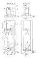
- the plug 2 is composed of a number of sections, of which the sections 3 and 4 are shown in FIGS. 1 and 2. Each section 3 and 4 has a steel plate 5. The individual steel plates 5 overlap, from top to bottom so that the lower end of an upper steel plate 5 overlaps the upper end of a subsequent lower steel plate 5.
- the steel plates 5 are provided with tabs at each end.
- the tabs on the upper steel sheet end serve to lock the associated steel sheet end, while the tabs on the lower steel sheet end are intended to enable longitudinally displaceable storage for thermal expansion of the sheets downwards.
- the tab of section 4 at the lower end of sheet steel is designated by 6, that at the upper end of section 3 by 7 and that at the lower end of section 3 by 8.
- the tab 6 is guided with bolts 9 in the tab 7 so as to be longitudinally displaceable. For this purpose, there is a sufficient section for the thermal expansion of the steel sheet 5 of section 4 between the tabs 6 and 7.
- the tab 7 is in turn on a bracket 10 attached to the door body 1. Between the bracket 10 and the tab 7 there is a schematically indicated bolt or screw connection which defines the upper end of section 3. The same arrangement exists at the upper end of section 4. At the lower end of section 3, a bracket 11 enables longitudinally displaceable storage for thermal expansion. The bracket 11 is fastened to the door frame and guides the lower end of the section 3 with a bolt 12 which is displaceable longitudinally in the bracket 8.
- the cavity existing between the steel plates 5 and the door body 1 forms a vertical gas collection space, via which the gaseous coking products are advantageously derived and fed to the upper gas collection tube and the riser tube. Due to the resulting favorable gas pressure conditions, the pressure structure on the door frame or on the coke oven door as a whole is so favorable to the respective outer atmosphere that emissions on the coke oven doors are prevented with conventional sealing strips.
- the steel plates 5 have a high thermal conductivity.
- the high thermal conductivity also results in the supply of heat via the steel plates 5. This effect allows the plate to protrude less than 100 mm into the furnace chamber. This is equivalent to an increase in the usable oven volume while the head sections are cooked consistently.
- the coke oven chamber door according to FIGS. 4 to 7 differs from the coke oven chamber door according to FIGS. 1 to 3 both by a different suspension of the sections 3 and 4 in the connecting area 13 and by a different arrangement at the foot of the plug 2.
- the latter area is marked with 14.
- the tab 7 is provided at the connection point with the bracket 10 with an elongated hole 15, which enables a thermal expansion of the steel plate 5 in the longitudinal direction of the door within the scope of section 3.
- the connection between the tab 7 and the bracket 10 is made by a bolt arranged in the bracket 10 and shown schematically, which slides in the slot 15.
- the console 16 extends essentially to the steel plate 5 of section 3 and is connected to a slide shoe 17 on the underside.
- section 3 is stiffened with the bracket 16 and is additionally protected against damage by the sliding shoe 17. In this way it is achieved that neither damage to the door structure nor to the frame or the sole stones can occur when inserting the door, regardless of the operation of the door operating machines.
Landscapes
- Chemical & Material Sciences (AREA)
- Engineering & Computer Science (AREA)
- Materials Engineering (AREA)
- Oil, Petroleum & Natural Gas (AREA)
- Organic Chemistry (AREA)
- Coke Industry (AREA)
Claims (3)
Applications Claiming Priority (2)
| Application Number | Priority Date | Filing Date | Title |
|---|---|---|---|
| DE3201521 | 1982-01-20 | ||
| DE3201521A DE3201521A1 (de) | 1982-01-20 | 1982-01-20 | "koksofenkammertuer" |
Publications (3)
| Publication Number | Publication Date |
|---|---|
| EP0084366A1 EP0084366A1 (fr) | 1983-07-27 |
| EP0084366B1 EP0084366B1 (fr) | 1985-05-29 |
| EP0084366B2 true EP0084366B2 (fr) | 1989-12-27 |
Family
ID=6153413
Family Applications (1)
| Application Number | Title | Priority Date | Filing Date |
|---|---|---|---|
| EP83100326A Expired EP0084366B2 (fr) | 1982-01-20 | 1983-01-15 | Porte pour chambre de four à coke |
Country Status (6)
| Country | Link |
|---|---|
| US (1) | US4502922A (fr) |
| EP (1) | EP0084366B2 (fr) |
| JP (1) | JPS58502218A (fr) |
| AU (1) | AU554349B2 (fr) |
| DE (1) | DE3201521A1 (fr) |
| WO (1) | WO1983002454A1 (fr) |
Families Citing this family (2)
| Publication number | Priority date | Publication date | Assignee | Title |
|---|---|---|---|---|
| DE3344976C2 (de) * | 1983-05-04 | 1985-02-28 | WSW Planungsgesellschaft mbH, 4355 Waltrop | Koksofentür in Leichtbauweise |
| US4647343A (en) * | 1984-05-03 | 1987-03-03 | Wsw Planungs - Gmbh | Self sealing coke oven door of lightweight construction |
Family Cites Families (9)
| Publication number | Priority date | Publication date | Assignee | Title |
|---|---|---|---|---|
| US4086145A (en) * | 1977-03-14 | 1978-04-25 | Jones & Laughlin Steel Corporation | Coke oven door lining |
| US4217177A (en) * | 1978-12-05 | 1980-08-12 | Jones & Laughlin Steel Corporation | Vented coke oven door apparatus |
| EP0028679B1 (fr) * | 1979-11-08 | 1983-06-08 | WSW Planungs-GmbH | Porte de four à coke ayant un espace collecteur de gaz de grand volume |
| ATE3724T1 (de) * | 1979-11-08 | 1983-06-15 | Wsw-Planungsgesellschaft Mbh | Koksofentuer mit grossvolumigem gassammelraum. |
| DE3000161A1 (de) * | 1980-01-04 | 1981-07-09 | Ruhrkohle Ag, 4300 Essen | Koksofenkammertuere mit einem feuerfesten stopfen |
| DE3044607C2 (de) * | 1980-11-27 | 1985-04-18 | Carl Still Gmbh & Co Kg, 4350 Recklinghausen | Fußsteinhalter für Koksofentüren |
| US4381972A (en) * | 1981-02-17 | 1983-05-03 | Wsw-Planungs-Gmbh | Coke-oven door |
| ZA82980B (en) * | 1981-02-17 | 1983-01-26 | Wsw Planungsges | Process of coking coal |
| EP0058320B1 (fr) * | 1981-02-17 | 1985-05-02 | WSW Planungs-GmbH | Procédé de cokéfaction de charbon et four à coke pour la mise en oeuvre du procédé |
-
1982
- 1982-01-20 DE DE3201521A patent/DE3201521A1/de not_active Withdrawn
-
1983
- 1983-01-15 AU AU11048/83A patent/AU554349B2/en not_active Ceased
- 1983-01-15 US US06/537,404 patent/US4502922A/en not_active Expired - Fee Related
- 1983-01-15 EP EP83100326A patent/EP0084366B2/fr not_active Expired
- 1983-01-15 JP JP83500384A patent/JPS58502218A/ja active Pending
- 1983-01-15 WO PCT/DE1983/000004 patent/WO1983002454A1/fr not_active Ceased
Also Published As
| Publication number | Publication date |
|---|---|
| US4502922A (en) | 1985-03-05 |
| JPS58502218A (ja) | 1983-12-22 |
| EP0084366A1 (fr) | 1983-07-27 |
| EP0084366B1 (fr) | 1985-05-29 |
| DE3201521A1 (de) | 1983-07-28 |
| WO1983002454A1 (fr) | 1983-07-21 |
| AU554349B2 (en) | 1986-08-14 |
| AU1104883A (en) | 1983-07-28 |
Similar Documents
| Publication | Publication Date | Title |
|---|---|---|
| EP0028679A1 (fr) | Porte de four à coke ayant un espace collecteur de gaz de grand volume | |
| DE2218192A1 (de) | Walzenwechsel vorrichtung für ein Walzwerk oder Walzgerüst | |
| DE2831251C2 (de) | Hubplattenofen | |
| EP0084366B2 (fr) | Porte pour chambre de four à coke | |
| EP1814962B1 (fr) | Dispositif et procede de production horizontale de gateau de charbon compact | |
| DE3739452C1 (de) | Koksofentuer mit keramischem Schildaufbau | |
| DE2317685C3 (fr) | ||
| DE2850536C2 (de) | Dampferzeuger mit Wirbelschicht-Brennkammer | |
| DE2317685A1 (de) | Planiervorrichtung fuer verkokungsoefen | |
| EP0058320B1 (fr) | Procédé de cokéfaction de charbon et four à coke pour la mise en oeuvre du procédé | |
| DE8201167U1 (de) | Koksofenkammertür | |
| DE3505551C2 (de) | Koksofentür mit einem keramischen Stopfen | |
| EP0081619B1 (fr) | Dispositif de transfert de chaleur à lit fluidisé | |
| DE102012008936B3 (de) | Planierkasten einer Koksofenkammer mit einem darin enthaltenen feuerfesten Formkörper als Abstreifkontur, Planierstange und Verfahren zum Planieren einer Kohleschüttung in einer befüllten Koksofenkammer | |
| CH646243A5 (de) | Verfahren und vorrichtung zum trennen und entnehmen eines durch brennen und pyroplastische bindung des brenngutes gebildeten formkoerpers aus der form. | |
| DE511588C (de) | Vorrichtung zum Verkoken von Kohle o. dgl. | |
| DE9414691U1 (de) | Vorrichtung zum Beschicken eines Kehrrichtverbrennungsrostes | |
| AT204580B (de) | Schmelz- oder Wärmofen, insbesondere für Metalle | |
| DE2204188C3 (de) | Vorrichtung zum Brennputzen von Halbzeugoberflächen | |
| EP0321642B1 (fr) | Porte de four à coke avec écran métallique | |
| DE3408460A1 (de) | Koksofentuer mit separatem waermeschutzschild | |
| DE3743156A1 (de) | Koksofentuer mit metallschild | |
| DE210342C (fr) | ||
| DE19508848C2 (de) | Feuerfestes Formteil für Drehherdöfen | |
| DE740633C (de) | Verfahren zur Koks- und Gaserzeugung in aussen beheizten waagerechten Kammeroefen bei hohen Temperaturen mit Gasabsaugung bei Unterdruck |
Legal Events
| Date | Code | Title | Description |
|---|---|---|---|
| PUAI | Public reference made under article 153(3) epc to a published international application that has entered the european phase |
Free format text: ORIGINAL CODE: 0009012 |
|
| AK | Designated contracting states |
Designated state(s): BE FR GB IT LU NL |
|
| 17P | Request for examination filed |
Effective date: 19830812 |
|
| ITF | It: translation for a ep patent filed | ||
| GRAA | (expected) grant |
Free format text: ORIGINAL CODE: 0009210 |
|
| AK | Designated contracting states |
Designated state(s): BE FR GB IT LU NL |
|
| RAP2 | Party data changed (patent owner data changed or rights of a patent transferred) |
Owner name: STEWEN, WILHELM, DR.-ING. |
|
| ET | Fr: translation filed | ||
| BECN | Be: change of holder's name |
Effective date: 19850529 |
|
| PG25 | Lapsed in a contracting state [announced via postgrant information from national office to epo] |
Ref country code: LU Free format text: LAPSE BECAUSE OF NON-PAYMENT OF DUE FEES Effective date: 19860131 |
|
| PLBI | Opposition filed |
Free format text: ORIGINAL CODE: 0009260 |
|
| 26 | Opposition filed |
Opponent name: J. STOG TEC GMBH Effective date: 19860227 |
|
| NLR1 | Nl: opposition has been filed with the epo |
Opponent name: J. STOG TEC GMBH |
|
| PGFP | Annual fee paid to national office [announced via postgrant information from national office to epo] |
Ref country code: NL Payment date: 19890131 Year of fee payment: 8 |
|
| PUAH | Patent maintained in amended form |
Free format text: ORIGINAL CODE: 0009272 |
|
| STAA | Information on the status of an ep patent application or granted ep patent |
Free format text: STATUS: PATENT MAINTAINED AS AMENDED |
|
| PGFP | Annual fee paid to national office [announced via postgrant information from national office to epo] |
Ref country code: BE Payment date: 19891222 Year of fee payment: 8 |
|
| 27A | Patent maintained in amended form |
Effective date: 19891227 |
|
| AK | Designated contracting states |
Kind code of ref document: B2 Designated state(s): BE FR GB IT LU NL |
|
| PGFP | Annual fee paid to national office [announced via postgrant information from national office to epo] |
Ref country code: LU Payment date: 19891229 Year of fee payment: 8 |
|
| ITF | It: translation for a ep patent filed | ||
| ITTA | It: last paid annual fee | ||
| PGFP | Annual fee paid to national office [announced via postgrant information from national office to epo] |
Ref country code: GB Payment date: 19900131 Year of fee payment: 8 |
|
| NLR2 | Nl: decision of opposition | ||
| NLR3 | Nl: receipt of modified translations in the netherlands language after an opposition procedure | ||
| ET3 | Fr: translation filed ** decision concerning opposition | ||
| PG25 | Lapsed in a contracting state [announced via postgrant information from national office to epo] |
Ref country code: GB Effective date: 19910115 |
|
| PG25 | Lapsed in a contracting state [announced via postgrant information from national office to epo] |
Ref country code: BE Effective date: 19910131 |
|
| PG25 | Lapsed in a contracting state [announced via postgrant information from national office to epo] |
Ref country code: NL Effective date: 19910801 |
|
| GBPC | Gb: european patent ceased through non-payment of renewal fee | ||
| NLV4 | Nl: lapsed or anulled due to non-payment of the annual fee | ||
| PGFP | Annual fee paid to national office [announced via postgrant information from national office to epo] |
Ref country code: FR Payment date: 19911212 Year of fee payment: 10 |
|
| PG25 | Lapsed in a contracting state [announced via postgrant information from national office to epo] |
Ref country code: FR Effective date: 19930930 |
|
| REG | Reference to a national code |
Ref country code: FR Ref legal event code: ST |
|
| APAC | Appeal dossier modified |
Free format text: ORIGINAL CODE: EPIDOS NOAPO |
|
| APAC | Appeal dossier modified |
Free format text: ORIGINAL CODE: EPIDOS NOAPO |
|
| APAH | Appeal reference modified |
Free format text: ORIGINAL CODE: EPIDOSCREFNO |