EP0321642B1 - Porte de four à coke avec écran métallique - Google Patents
Porte de four à coke avec écran métallique Download PDFInfo
- Publication number
- EP0321642B1 EP0321642B1 EP88109176A EP88109176A EP0321642B1 EP 0321642 B1 EP0321642 B1 EP 0321642B1 EP 88109176 A EP88109176 A EP 88109176A EP 88109176 A EP88109176 A EP 88109176A EP 0321642 B1 EP0321642 B1 EP 0321642B1
- Authority
- EP
- European Patent Office
- Prior art keywords
- bars
- strips
- elements
- sealing element
- fastening elements
- Prior art date
- Legal status (The legal status is an assumption and is not a legal conclusion. Google has not performed a legal analysis and makes no representation as to the accuracy of the status listed.)
- Expired - Lifetime
Links
- 229910052751 metal Inorganic materials 0.000 title claims description 14
- 239000002184 metal Substances 0.000 title claims description 14
- 239000000571 coke Substances 0.000 title claims description 12
- 238000007789 sealing Methods 0.000 claims description 25
- 239000007787 solid Substances 0.000 claims 1
- 238000010276 construction Methods 0.000 description 15
- 230000005540 biological transmission Effects 0.000 description 9
- 229910000831 Steel Inorganic materials 0.000 description 7
- 239000010959 steel Substances 0.000 description 7
- 239000000725 suspension Substances 0.000 description 6
- PXHVJJICTQNCMI-UHFFFAOYSA-N Nickel Chemical compound [Ni] PXHVJJICTQNCMI-UHFFFAOYSA-N 0.000 description 2
- 239000000956 alloy Substances 0.000 description 2
- 229910045601 alloy Inorganic materials 0.000 description 2
- 238000005452 bending Methods 0.000 description 2
- 230000008642 heat stress Effects 0.000 description 2
- 239000000463 material Substances 0.000 description 2
- 239000007769 metal material Substances 0.000 description 2
- 230000000704 physical effect Effects 0.000 description 2
- VYZAMTAEIAYCRO-UHFFFAOYSA-N Chromium Chemical compound [Cr] VYZAMTAEIAYCRO-UHFFFAOYSA-N 0.000 description 1
- RTAQQCXQSZGOHL-UHFFFAOYSA-N Titanium Chemical compound [Ti] RTAQQCXQSZGOHL-UHFFFAOYSA-N 0.000 description 1
- 229910052782 aluminium Inorganic materials 0.000 description 1
- XAGFODPZIPBFFR-UHFFFAOYSA-N aluminium Chemical compound [Al] XAGFODPZIPBFFR-UHFFFAOYSA-N 0.000 description 1
- 239000000919 ceramic Substances 0.000 description 1
- 229910052804 chromium Inorganic materials 0.000 description 1
- 239000011651 chromium Substances 0.000 description 1
- 210000000078 claw Anatomy 0.000 description 1
- 239000003245 coal Substances 0.000 description 1
- 238000004939 coking Methods 0.000 description 1
- 238000011161 development Methods 0.000 description 1
- 230000018109 developmental process Effects 0.000 description 1
- 238000009826 distribution Methods 0.000 description 1
- 238000010438 heat treatment Methods 0.000 description 1
- 238000009413 insulation Methods 0.000 description 1
- 238000004519 manufacturing process Methods 0.000 description 1
- 238000000034 method Methods 0.000 description 1
- 229910052759 nickel Inorganic materials 0.000 description 1
- 230000008092 positive effect Effects 0.000 description 1
- 238000003825 pressing Methods 0.000 description 1
- 230000001681 protective effect Effects 0.000 description 1
- 229910052710 silicon Inorganic materials 0.000 description 1
- 239000010703 silicon Substances 0.000 description 1
- 230000003068 static effect Effects 0.000 description 1
- 239000004575 stone Substances 0.000 description 1
- 230000035882 stress Effects 0.000 description 1
- 239000010936 titanium Substances 0.000 description 1
- 229910052719 titanium Inorganic materials 0.000 description 1
Images


Classifications
-
- C—CHEMISTRY; METALLURGY
- C10—PETROLEUM, GAS OR COKE INDUSTRIES; TECHNICAL GASES CONTAINING CARBON MONOXIDE; FUELS; LUBRICANTS; PEAT
- C10B—DESTRUCTIVE DISTILLATION OF CARBONACEOUS MATERIALS FOR PRODUCTION OF GAS, COKE, TAR, OR SIMILAR MATERIALS
- C10B25/00—Doors or closures for coke ovens
- C10B25/02—Doors; Door frames
- C10B25/06—Doors; Door frames for ovens with horizontal chambers
Definitions
- the invention relates to a coke oven door, consisting of a hollow profile frame for receiving pressure elements and fastening elements, a sealing unit with an outer sealing element and an inner sealing element and a metal plate assigned to the inner sealing element.
- Such a coke oven door is known from DE 34 40 312 Al.
- the metal plate consists of several large-sized sheet metal sections arranged one above the other, each sheet plate section consisting of several sheet metal sheets arranged one behind the other from shaped profiles. It is disadvantageous that the large-sized metal sheets tend to deform as a result of heat stress.
- the invention is also based on this object.
- the metal plate is composed of a plurality of individual bars or strips or strips or grids arranged one above the other or next to one another, which are connected to the inner sealing element serving as a supporting element in a tension-free manner via fastening elements.
- the support according to the invention is effected by a one-part or multi-part door box which is arranged behind the bars or strips or the grille.
- the rods according to the invention can have a full profile or can be formed by a hollow profile.
- the cross-sectional shape of the bars can be square, rectangular or round. Irregularly shaped cross sections are also conceivable.
- the bars have a thickness of 10 to 30 mm. Bands differ from the bars by a significantly smaller thickness, namely 4 to 10 mm, and by a larger width, namely up to 100 mm.
- the bars or strips can run transversely to the longitudinal direction of the door or in the longitudinal direction of the door.
- Fastening elements are optionally provided according to the invention for fastening, which cover the strips or bars transversely to their longitudinal direction.
- Such fasteners can in turn be formed by bands that are hinged to the back of the support or extend to the rest of the door body.
- Thinner rods are also suitable as fastening elements, which reach into the rods forming the actual metal shield through corresponding openings.
- the fastening elements can also be arranged laterally and have recesses into which the rods and / or strips are inserted in the longitudinal direction or into which the rods or strips are inserted from the front transversely to their longitudinal direction.
- the individual rods or strips can also be suspended individually or in groups from the support.
- the groups preferably have a height of 200 to 400 mm in the case of bars or strips running transversely to the longitudinal direction of the door.
- these groups also correspond to elements of the box forming the support. These elements of the box forming the support then have the same overall height as the groups of bars or strips. Slits are preferably provided between the elements of the box forming the support. The slots are said to allow the entry of raw gas during the coking process.
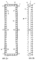
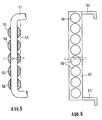
- Figures 5 to 8 show different mounting options for a metal plate made of rods.
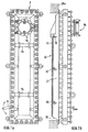
- the coke oven door consists of a power transmission unit 1 and a sealing unit 21.
- the power transmission unit 1 is formed in Fig. 2 as a hollow profile frame 24, the longitudinal spars in Fig. 3 with 22 and the cross bars in Fig. 3 with 23.
- the longitudinal bars 22 are open at the upper and lower ends. Furthermore, there are 4 openings in the longitudinal spars at the junctures to the transverse spars, so that heating air in the hollow profile frame 24 unhindered from the transverse spars 23 into the longitudinal spars 22 and flow up there and can emerge from the hollow profile frame 24 at the top.
- the hollow profile frame 24 shown in the exemplary embodiment according to FIG. 2 is provided with a multiplicity of pressure elements 28 which are rotatable in themselves.
- these pressure elements 28 are composed of a movable sleeve 5, a spindle 3 fixedly connected to the sleeve 5 and a sprocket 2 fixedly attached to the spindle 3.
- the spindle 3 is rotatably guided in a threaded sleeve 4 .
- the threaded sleeve 4 according to Fig. 3 is firmly welded into the hollow profile frame 24 according to Fig. 2.
- bolts 7 are welded to the outer flanks of the longitudinal spars 22 according to Fig. 3 and to the chamber frame 28 Fig. 3 adjustable hooks for receiving the bolts 7 attached.
- the number of hooks 8 depends on the number of bolts 7 and is 6.
- the number of bolts 7 depends on the furnace height. With a furnace height of 4 m, a total of 4 bolts are sufficient, in the arrangement of 2 at the top and bottom of the hollow profile frame 24 according to Fig. 2.
- the pressing forces of the individual elements 28 according to Fig. 2 on the sealing unit 21 according to Fig. 3 is generated by a rotating chain hoist 27 according to Fig. 2. With this arrangement there is thus a constant distribution of forces guaranteed via the power transmission unit 1 according to Fig. 2 to the sealing unit 21 according to Fig. 3.
- the pivot point 30 according to FIG. 2 for moving the circulating chain 27 according to FIG. 2 can be transferred to each pressure element 28.
- the torque required for point 30 is generated by a torque motor, which is not shown in the figure. This torque motor can be installed both directly on the power transmission unit 1 and on door operating machines which are present during operation.
- the square hollow profile frame 24 shown in the exemplary embodiment according to FIG. 3 can be replaced by the choice of other profiles.
- Geometries of commercially available profiles such as rectangular hollow profiles, U profiles, L profiles, double T profiles, tubular profiles and simple flat profiles allow the pressure elements 28 to be accommodated.
- the sealing unit 21 consists of the sealing element 9 and an insulation 29.
- the sealing element 9 forms a hollow body with the element 10.
- Both elements 9 and 10 are made of a heat-resistant metallic material.
- a thickness of between 2 and 4 mm per sealing element is provided. The overall height of the furnace and its width have no influence on the thickness, since the restoring forces of the furnace filling do not differ significantly from one another in common furnace sizes.
- the elements 9 and 10 have the same profile according to Fig. 3 and are firmly connected to each other. A loose arrangement of element 10 on element 9 is feasible.
- the hollow body formed by the elements 9 and 10 can, on the one hand, be designed as closed and, on the other hand, can be made open via the element 10 towards the interior of the open.
- the element 10 is formed with lateral slits or is open at the top and bottom in the vertical direction. This results in the possibility of expanding the two gas channels, formed by the shield construction 11 according to FIG. 3 and the side surfaces of the element 10, in order to expand the gas channel formed by the hollow body.
- the gas channel is expanded by up to 100%. This expansion of the gas channel has a very positive effect on the static pressure behavior in the channel and therefore on the tightness of the door.
- Fig. 1 the usual door foot does not apply to the door.
- the inner element 10 according to Fig. 3 takes over the function of a door foot 35 due to its design.
- a metal U-seal 14 is provided as an exemplary embodiment between the free leg 31 according to FIG. 3 and the sealing surface of the door frame.
- the sealing unit 21 is held loosely by the power transmission unit 1 in the exposed state via brackets 12 and 25. In the inserted state, the brackets 12 and 25 become ineffective, so that the different rotational capacity due to the different temperature positions of the sealing unit 21 and the power transmission unit 1 is taken into account.
- cross bars 34 are arranged between the bars 22. These cross bars serve as a lifting point of attack for the claws present on the door lifting machines, which are not shown in the drawings.
- the "heat shield” 33 no longer consists, as usual, of flat, one-piece, heat-resistant metallic plates of different designs, but instead of a multiplicity of heat-resistant metallic round bars 11 of the same cross section _ arranged transversely to the furnace chamber _ in front of the inner screed 10 according to FIG. 3 loosely attached via breakpoints 32.
- the individual round bars between 20 and 30 mm thick are drilled through at two points to accommodate the suspension.
- a level surface is created over the furnace height to accommodate the coal front when filling the coke oven.
- the individual rods 11 and the suspensions 32 behave more dimensionally stable at high temperatures, since both each rod can expand freely in the transverse direction to the furnace and the suspension rods can extend freely in the vertical direction to the furnace.
- other geometries of the rod construction with the same physical properties can be integrated, such as square, rectangular and strip-like shapes.
- the one-piece rod construction according to Figs. 1 and 3 can also be carried out as a multi-part construction over the height of the inner screed 10. Furthermore, the rod construction also allows a rod guide in the vertical direction, not shown in the drawings. Here, the Bars guided in parallel as a continuous unit, held with cross bars distributed over the height.
- the leveling door 36 according to Fig. 1 and 4 is designed in a circular construction.
- the leveling box 14 designed as a tube according to Figure 4 takes up the sealing surface 15.
- a metallic cover 16 is pressed in front of this sealing surface 15 via the force transmission frame 17 via bolts or springs 39.
- the fixed points 19 and 20 become effective.
- the fixed point 19 is designed as a hinge in order to pivot the leveling door 36.
- the fixed point 20 is effective via a handwheel 37 with a spindle which is mounted in the joint 38.
- each group has an overall height of 300 mm in the exemplary embodiment. All bars have a round cross-section.
- the rod diameter is 20 mm.
- the bars labeled 50 there are drilled through, so that a 10 mm thick wire or bar can be passed through the individual bars 50 and bent over.
- the individual rods 50 are held together by the rod designated 51.
- the rods 50 can be hung on the rod 51 at the same time.
- the suspension is otherwise the same as for the individual rods according to FIG. 1.
- dash-dotted line 52 indicates the support line through elements 10.
- Figure 6 shows rods 60 with a round cross-section and 15 mm in diameter.
- the rods 60 are held in side plates 61.
- the sheets 61 are provided with bores into which the rods 60 are inserted in the longitudinal direction.
- the rods 60 form with the sheets 61 elements which are hung on hooks 62.
- the embodiment according to Figure 8 differs from that according to Figure 6 in that the rods are not inserted in the longitudinal direction but are inserted transversely to their longitudinal direction from the front into sheets 80 which have hook-shaped depressions 82 for the rods denoted by 81.
Landscapes
- Chemical & Material Sciences (AREA)
- Engineering & Computer Science (AREA)
- Materials Engineering (AREA)
- Oil, Petroleum & Natural Gas (AREA)
- Organic Chemistry (AREA)
- Coke Industry (AREA)
Claims (13)
Applications Claiming Priority (2)
| Application Number | Priority Date | Filing Date | Title |
|---|---|---|---|
| DE19873743156 DE3743156A1 (de) | 1987-08-03 | 1987-12-19 | Koksofentuer mit metallschild |
| DE3743156 | 1987-12-19 |
Publications (2)
| Publication Number | Publication Date |
|---|---|
| EP0321642A1 EP0321642A1 (fr) | 1989-06-28 |
| EP0321642B1 true EP0321642B1 (fr) | 1991-04-24 |
Family
ID=6343018
Family Applications (1)
| Application Number | Title | Priority Date | Filing Date |
|---|---|---|---|
| EP88109176A Expired - Lifetime EP0321642B1 (fr) | 1987-12-19 | 1988-06-09 | Porte de four à coke avec écran métallique |
Country Status (2)
| Country | Link |
|---|---|
| EP (1) | EP0321642B1 (fr) |
| DE (1) | DE3862579D1 (fr) |
Family Cites Families (2)
| Publication number | Priority date | Publication date | Assignee | Title |
|---|---|---|---|---|
| DE3440312A1 (de) * | 1984-01-05 | 1985-07-25 | Ruhrkohle Ag, 4300 Essen | Schutzschild fuer koksofentuer |
| DE3528511C1 (de) * | 1985-08-08 | 1986-08-14 | Carl Still Gmbh & Co Kg, 4350 Recklinghausen | Leichtbaukoksofentuer |
-
1988
- 1988-06-09 EP EP88109176A patent/EP0321642B1/fr not_active Expired - Lifetime
- 1988-06-09 DE DE8888109176T patent/DE3862579D1/de not_active Expired - Lifetime
Also Published As
| Publication number | Publication date |
|---|---|
| EP0321642A1 (fr) | 1989-06-28 |
| DE3862579D1 (de) | 1991-05-29 |
Similar Documents
| Publication | Publication Date | Title |
|---|---|---|
| EP0291701B1 (fr) | Appareil de préchauffage d'une charge dans une installation métallurgique de fusion | |
| DE2742877B2 (de) | Wärmeübertrager, insbesondere Rekuperator für Hochtemperaturreaktoren | |
| EP0317494B1 (fr) | Porte de four à coke d'une construction à bouclier céramique | |
| EP0321642B1 (fr) | Porte de four à coke avec écran métallique | |
| DE3743156A1 (de) | Koksofentuer mit metallschild | |
| DE2436334C2 (de) | Verfahren zur Erwärmung von Knüppeln in Hubstransportöfen und Hubtransportofen zur Durchführung des Verfahrens | |
| EP0063700A2 (fr) | Procédé pour rendre étanche les portes de fours à coke horizontaux et fours à coke avec portes de fours à coke | |
| EP0058320B1 (fr) | Procédé de cokéfaction de charbon et four à coke pour la mise en oeuvre du procédé | |
| DE4029010C1 (fr) | ||
| EP0321640B1 (fr) | Porte de four à coke d'une construction avec écran | |
| DE3327337A1 (de) | Koksofentueren fuer horizontalkammerverkokungsoefen | |
| DE2929322C2 (de) | Anwärmofen | |
| DE3743679A1 (de) | Koksofentuer | |
| DE3344976A1 (de) | Koksofentuer in leichtbauweise | |
| DE3505551C2 (de) | Koksofentür mit einem keramischen Stopfen | |
| EP0383813B1 (fr) | Bati de chambre | |
| EP0114183B1 (fr) | Porte pour four à coke à chambres horizontales | |
| EP0084366B2 (fr) | Porte pour chambre de four à coke | |
| DE3348043C2 (en) | Coke oven door with sheet pile | |
| DE1758785C3 (de) | Feuerfeste Ummantelung für Stützglieder von Wärmebehandlungsöfen | |
| DE3147918C1 (de) | Hochtemperaturbeanspruchbare Auskleidung für einen Behälter | |
| AT204580B (de) | Schmelz- oder Wärmofen, insbesondere für Metalle | |
| DE2807612A1 (de) | Waermetauscher | |
| DE3743157A1 (de) | Koksofentuer mit schildkonstruktion | |
| DE8128278U1 (de) | Koksofentuer |
Legal Events
| Date | Code | Title | Description |
|---|---|---|---|
| PUAI | Public reference made under article 153(3) epc to a published international application that has entered the european phase |
Free format text: ORIGINAL CODE: 0009012 |
|
| AK | Designated contracting states |
Kind code of ref document: A1 Designated state(s): BE DE FR GB IT NL |
|
| 17P | Request for examination filed |
Effective date: 19890509 |
|
| 17Q | First examination report despatched |
Effective date: 19900220 |
|
| ITF | It: translation for a ep patent filed | ||
| GRAA | (expected) grant |
Free format text: ORIGINAL CODE: 0009210 |
|
| AK | Designated contracting states |
Kind code of ref document: B1 Designated state(s): BE DE FR GB IT NL |
|
| REF | Corresponds to: |
Ref document number: 3862579 Country of ref document: DE Date of ref document: 19910529 |
|
| GBT | Gb: translation of ep patent filed (gb section 77(6)(a)/1977) | ||
| ET | Fr: translation filed | ||
| PLBE | No opposition filed within time limit |
Free format text: ORIGINAL CODE: 0009261 |
|
| STAA | Information on the status of an ep patent application or granted ep patent |
Free format text: STATUS: NO OPPOSITION FILED WITHIN TIME LIMIT |
|
| 26N | No opposition filed | ||
| PGFP | Annual fee paid to national office [announced via postgrant information from national office to epo] |
Ref country code: FR Payment date: 19930512 Year of fee payment: 6 |
|
| PGFP | Annual fee paid to national office [announced via postgrant information from national office to epo] |
Ref country code: GB Payment date: 19930519 Year of fee payment: 6 |
|
| PGFP | Annual fee paid to national office [announced via postgrant information from national office to epo] |
Ref country code: BE Payment date: 19930527 Year of fee payment: 6 |
|
| PGFP | Annual fee paid to national office [announced via postgrant information from national office to epo] |
Ref country code: NL Payment date: 19930630 Year of fee payment: 6 |
|
| PGFP | Annual fee paid to national office [announced via postgrant information from national office to epo] |
Ref country code: DE Payment date: 19940112 Year of fee payment: 6 |
|
| PG25 | Lapsed in a contracting state [announced via postgrant information from national office to epo] |
Ref country code: GB Effective date: 19940609 |
|
| PG25 | Lapsed in a contracting state [announced via postgrant information from national office to epo] |
Ref country code: BE Effective date: 19940630 |
|
| BERE | Be: lapsed |
Owner name: RUHRKOHLE A.G. Effective date: 19940630 |
|
| PG25 | Lapsed in a contracting state [announced via postgrant information from national office to epo] |
Ref country code: NL Effective date: 19950101 |
|
| GBPC | Gb: european patent ceased through non-payment of renewal fee |
Effective date: 19940609 |
|
| NLV4 | Nl: lapsed or anulled due to non-payment of the annual fee | ||
| PG25 | Lapsed in a contracting state [announced via postgrant information from national office to epo] |
Ref country code: FR Effective date: 19950228 |
|
| PG25 | Lapsed in a contracting state [announced via postgrant information from national office to epo] |
Ref country code: DE Effective date: 19950301 |
|
| REG | Reference to a national code |
Ref country code: FR Ref legal event code: ST |
|
| PG25 | Lapsed in a contracting state [announced via postgrant information from national office to epo] |
Ref country code: IT Free format text: LAPSE BECAUSE OF NON-PAYMENT OF DUE FEES Effective date: 20050609 |