EP0084620A2 - Appareil pour cercler des balles - Google Patents
Appareil pour cercler des balles Download PDFInfo
- Publication number
- EP0084620A2 EP0084620A2 EP82110703A EP82110703A EP0084620A2 EP 0084620 A2 EP0084620 A2 EP 0084620A2 EP 82110703 A EP82110703 A EP 82110703A EP 82110703 A EP82110703 A EP 82110703A EP 0084620 A2 EP0084620 A2 EP 0084620A2
- Authority
- EP
- European Patent Office
- Prior art keywords
- wire
- bale
- lacing
- twisting
- machine according
- Prior art date
- Legal status (The legal status is an assumption and is not a legal conclusion. Google has not performed a legal analysis and makes no representation as to the accuracy of the status listed.)
- Granted
Links
- 238000005553 drilling Methods 0.000 claims abstract description 22
- 238000003825 pressing Methods 0.000 claims abstract description 16
- 238000005520 cutting process Methods 0.000 claims abstract description 12
- 239000002699 waste material Substances 0.000 claims abstract description 6
- 239000010893 paper waste Substances 0.000 claims description 3
- 239000000463 material Substances 0.000 abstract description 7
- 238000000034 method Methods 0.000 description 12
- 238000010276 construction Methods 0.000 description 3
- 238000004519 manufacturing process Methods 0.000 description 3
- 230000015572 biosynthetic process Effects 0.000 description 1
- 238000003780 insertion Methods 0.000 description 1
- 230000037431 insertion Effects 0.000 description 1
- 230000000750 progressive effect Effects 0.000 description 1
Images


Classifications
-
- B—PERFORMING OPERATIONS; TRANSPORTING
- B65—CONVEYING; PACKING; STORING; HANDLING THIN OR FILAMENTARY MATERIAL
- B65B—MACHINES, APPARATUS OR DEVICES FOR, OR METHODS OF, PACKAGING ARTICLES OR MATERIALS; UNPACKING
- B65B27/00—Bundling particular articles presenting special problems using string, wire, or narrow tape or band; Baling fibrous material, e.g. peat, not otherwise provided for
- B65B27/12—Baling or bundling compressible fibrous material, e.g. peat
-
- A—HUMAN NECESSITIES
- A01—AGRICULTURE; FORESTRY; ANIMAL HUSBANDRY; HUNTING; TRAPPING; FISHING
- A01F—PROCESSING OF HARVESTED PRODUCE; HAY OR STRAW PRESSES; DEVICES FOR STORING AGRICULTURAL OR HORTICULTURAL PRODUCE
- A01F15/00—Baling presses for straw, hay or the like
- A01F15/08—Details
- A01F15/14—Tying devices specially adapted for baling presses
- A01F15/146—Wire twisters
-
- B—PERFORMING OPERATIONS; TRANSPORTING
- B30—PRESSES
- B30B—PRESSES IN GENERAL
- B30B9/00—Presses specially adapted for particular purposes
- B30B9/30—Presses specially adapted for particular purposes for baling; Compression boxes therefor
- B30B9/3003—Details
Definitions
- the invention relates to a machine for pressing and tying bales of waste material, in particular waste paper, with a press box, a press die movable therein, a lacing device with a cutting and drilling device and with a lacing needle movable along a rear side of the bale for forming a wire loop over the bale surface. on which the twisting is to take place, out of the wire coming from a backward supply roll, passing the opposite bale long side and the front side, and with a device for the longitudinal transport of the wire in the pressing direction into the twisting position.
- a machine of the above type known from DE-PS 2 105 163 has a so-called single-wire lacing, in which the wire, which stands up with its free end in front of the bale and runs backwards under the bale to the supply roll, is moved through a lacing needle which can be moved along a rear side of the bale the top edge of the bale is raised.
- the length of the wire loop to be generated can be set by preselecting the length of the stroke of the lace.
- the wire loop formed in this way can have a wire length in the region projecting beyond the top of the bale, which corresponds to approximately twice the bale length. This measure is necessary so that even long bales can still be tied with wire.
- a swiveling and axially movable clamping and cutting device clamps the wire end associated with the bale back of the hoisted wire loop and detaches it.
- the clamping and cutting device then pivots the clamped wire end to form a crossing point next to the free wire end held by a magnetic holder.
- a twisting of the two wire ends takes place with one another, using a twisting device that engages from above and can be moved axially up and down.
- This clamping or take-over device represents an additional uncertainty factor in the known tying system, because the wire end to be taken over is not always precisely positioned and held taut in the tying plane as a result of wire warping, so that difficulties can arise in this regard when taking over.
- the wire end leading past the end of the bale must be designed so long before each lacing process that even the largest bale produced can still be wrapped with wire.
- the lacing needle must be raised so high in a bale that is produced too long that the wire loop formed has a length which corresponds to twice the bale length, for this purpose the lacing needle will require a correspondingly large stroke.
- the large stroke a relatively long period of time for a work cycle and a corresponding press and hall construction height are connected from a technical point of view, which leads to an expensive construction cost in economic terms.
- the invention is therefore based on the object to improve the above-mentioned device in such a way that the wire waste resulting from the tying of bales produced for too long is avoided in all cases and a functionally reliable and trouble-free lacing of the bales is ensured.
- this object is achieved in that the lacing needle can be moved with the wire loop parallel to the pressing direction up to the assumed position of the drilling device. With a tying device designed in this way, even excessively long bales can be tied automatically without any wire waste.
- the task of the lacing needle which can be moved in the pressing direction, is to transport the wire path leading past the underside of the bale, drawn up into a wire loop, over the top of the bale and to bring it to the position occupied by the free end of the wire held on the twisting device, where the two ends of the wire are then twisted together .
- the twisting device can be moved.
- the latter takes a fixed basic position approximately in the middle of the bale. a.
- it leaves egg during production Nes overlength bale their location and moves in the pressing direction with the wire stretch coming from the bale front side by the distance which is predetermined by the material compressed beyond a normal bale length.
- this mobility of the twisting device relative movements between the wire path lying on the underside and front end of the bale and the bale and overstressing of the twisting device due to tensile forces transmitted by wire are avoided in the mentioned operating case.
- a supporting measure for aligning the wire path involved in the twisting process is, in a further embodiment of the invention, that a guide is arranged on the lacing needle below the catch hook at a distance vertically aligned with the catch hook.
- the transport of the wire path into the twisting position is advantageously supported or facilitated by a guide groove worked into the tip of the lacing needle, which allows or takes over an additional centering of the wire path during transport over the top of the bale.
- the cord wire facing the drilling device is guided at least in the twisted position between the catch hook, guide and tip axially parallel to the other wire path to be combined therewith, so that the drilling device can pick up the wire properly and no time delay or mechanical hindrance in the workflow of the Drilling occurs.
- the lacing needle moved to the occupied position of the twisting device remains at this point until the separated wire section wrapped around the catch hook has been pulled off the catch hook by a newly created bale disk is and moves in the pressing direction by further produced bale disks with this.
- the wire path coming from the bale end side is held by at least one clamping piece, which also ensures a vertical alignment at the same time of the wire path in the tying plane or in the twisting position, which favors the insertion of the wire path into the twisting device.
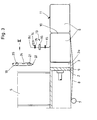
- a press channel 3 adjoins the press box 1, the cross section of which, calculated from the press box 1 to the outlet opening 4, narrows to a small extent to generate the desired counterforce.
- the inclination of at least one wall of the press channel 3 is adjustable.
- a filling shaft 5 opens from above, through which the material to be pressed is fed. To produce each bale, several working strokes of the press ram 2 in the pressing direction P indicated by the arrow are required.
- the press channel 3 there are in the press channel 3 there are already three pressed bales 6, of which the middle and the right are already tied with wire, while the left is ready for tying.
- the initially free end 8c of the wire 8 runs below the press box 1 via a deflection roller 9 around the front end face 10 of the bale to be tied and is at the top of this bale at a twist 11, the production of which is described below is connected to the other end 8b of the wire, which results from the pulled wire loop 8a, 8b.
- a housing 12, on rails, not shown, is identified in FIG. 1 by an arrow. draws, arranged back and forth.
- the housing 12 is a carrier of a twisting device 13 and a cutting device 14 and, in the exemplary embodiment shown, two clamping pieces 15, which are arranged above and below the twisting device 13 and by means of which the free wire end 8c coming from the end face 10 of the bale is clamped and vertically stretched out in the tying plane is held.
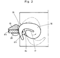
- the drilling device 13 is drawn in FIG. 1 in the already retracted state. According to FIG. 2, it contains, among other things, a seed wheel 16 with a slot 17, which is driven by a motor 18 via an intermediate gear at certain times.
- the cutting device which can be swiveled into the tying plane and is arranged above the drilling device 13, comes into action, which cuts through the twisting 11 or the wires 8b and 8c twisted together above the drilling point 11.
- a lacing needle 19 which is movable up and down in the direction of its longitudinal axis is provided with a catch hook 20 which is spaced x is arranged as a guide roller to a guide 21 aligned below with the fan hook in the example shown (see also FIG. 9). As explained in more detail below, this arrangement considerably facilitates the transport of the wire loop 8a, b with the lacing needle 19 over the top of the bale.
- the axially parallel guidance of the wire section 8b between the catch hook 20 and guide roller ensures a vertical alignment of the wire section 8b in the tying plane, which subsequently enables the wire section 8b to be twisted with the free wire end 8c.
- the lacing needle tip 22 is also provided with a guide slot 23 in order to facilitate the guiding or the transport of the wire path 8b over the top of the bale into the twisting position. So that the twisting device 13 can correctly grasp the wire path 8b to be twisted without colliding with the lacing needle shaft, a groove is incorporated or provided in the lacing needle shaft, as can be seen in FIGS. 1 to 8 and 9, so that drive the drilling wheel 16 through the groove 24 during the drilling process and can engage behind the wire path 8b to be twisted with the wire path 8c (FIG. 2).
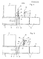
- the left waste paper bale 6 is just finished pressed, the press die 2 is in the right end position, so that the groove 2a formed in the head of the press die is aligned with the lacing needle.
- the wire 8 drawn off from the wire supply roll 7 leads past the underside, the end face 10 and the top of the bale 6 before it is deflected approximately in the middle of the bale by 90 ° to the bale axis.
- This wire path, later deflected by 90 ° and later involved in the twisting, is referred to below as wire path 8c.
- the wire path 8c is held vertically aligned in the tying plane by the clamping pieces 15 fastened to the movable housing 12.
- the drill device 13 and the cutting device 14, which are also fastened to the housing 12 and can thus be moved, are in a fixed basic position in the case of a bale which is of normal length or has been produced, as is shown, inter alia, in FIGS.
- the additional wire 8 required in the manufacture of the bale 6 or the newly produced material disc 6a is drawn off the wire supply roll 7 with each press stroke carried out, while the twisting device 13 remains in its assumed position.
- the drilling device 13 or the movable Ge leaves housing 12 its location and moves with the clamped wire section 8c by the distance - which is predetermined by the too much pressed material - in the pressing direction P to compensate for the difference in the different bale lengths.
- the lacing needle 19 has brought the wire loop 8a, b in the pressing direction P up to the position of the twisting device 13.
- the wire path 8b was centered between the catch hook 20, the lower guide roller 21a and the guide slot 23 incorporated in the tip of the cord needle 22, so that the wire path 8b could be transported into the twisting position under positive guidance.
- the cord 8b facing the twisting device 13 is guided, at least in the twisted position between the catch hook 20 and guide roller 21a, axially parallel to the other wire path 8c to be combined therewith - which is held vertically aligned by the clamping pieces 15 so that the drill 13 can grasp the wires 8b and 8c properly.
- the twist wheel 13 travels through the groove 24 machined at the level of the twist wheel 16 in the lacing needle shaft 19, as a result of which a collision of the twisting wheel 16 with the lacing needle 19 is avoided.
- the Wire path 8b and 8c are then twisted together (see FIG. 6). In FIG.
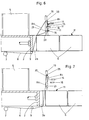
- the press ram 2 has already carried out new working strokes and pressed material discs 6a against the wire 8 running between the end face 10 of the new bale and the back side of the pressed bale 6 to form a new bale.
- the locking element 25 is released and thus the wire path lying around the catch hook 20 of the lace 19 is released.
- the lace 19 is one certain distance traveled up (see Fig. 8), so that due to the raising of the lacing needle 19 and the progressive formation of a new bale 6, the free wire end 8c is pulled from the hook 20 of the lacing needle 19 and the wire 8 between the back of the previous bale and the end face 10 of the bale being formed.
- the free end of the wire 8c bends, with the bale 6 continuing to advance, and reaches the position shown in FIG. 8 through the given positive guidance. Thereby arrives below.
- the lacing device according to the invention can also be used in the case of a two-wire lacing within the scope of the invention, the only difference from the single-wire lacing is that the initially free wire end, which in the previous exemplary embodiment is designated position 8c, is from a second one Wire supply roll comes while the second wire end is still pulled off from a wire supply roll marked item 7 in the single-wire tying example.
Landscapes
- Engineering & Computer Science (AREA)
- Mechanical Engineering (AREA)
- Life Sciences & Earth Sciences (AREA)
- Environmental Sciences (AREA)
- Basic Packing Technique (AREA)
Applications Claiming Priority (2)
| Application Number | Priority Date | Filing Date | Title |
|---|---|---|---|
| DE3202233A DE3202233C2 (de) | 1982-01-25 | 1982-01-25 | Vorrichtung zum Umschnüren von Ballen |
| DE3202233 | 1982-01-25 |
Publications (3)
| Publication Number | Publication Date |
|---|---|
| EP0084620A2 true EP0084620A2 (fr) | 1983-08-03 |
| EP0084620A3 EP0084620A3 (en) | 1984-05-09 |
| EP0084620B1 EP0084620B1 (fr) | 1987-03-25 |
Family
ID=6153831
Family Applications (1)
| Application Number | Title | Priority Date | Filing Date |
|---|---|---|---|
| EP82110703A Expired EP0084620B1 (fr) | 1982-01-25 | 1982-11-19 | Appareil pour cercler des balles |
Country Status (5)
| Country | Link |
|---|---|
| US (1) | US4466345A (fr) |
| EP (1) | EP0084620B1 (fr) |
| JP (1) | JPS58134827A (fr) |
| DE (2) | DE3202233C2 (fr) |
| ES (1) | ES8400320A1 (fr) |
Cited By (8)
| Publication number | Priority date | Publication date | Assignee | Title |
|---|---|---|---|---|
| EP0235378A3 (en) * | 1986-02-27 | 1989-02-22 | Paal's Packpressen-Fabrik Gmbh & Co. Kg | Machine for pressing and tying bales machine for pressing and tying bales |
| EP0400380A1 (fr) * | 1989-06-02 | 1990-12-05 | Lindemann Maschinenfabrik GmbH | Appareil pour cercler des balles faites dans une presse à balles |
| GB2246397A (en) * | 1990-07-27 | 1992-01-29 | Beakbane Limited | Fluid operated actuator comprising an expandable bag |
| GB2253011A (en) * | 1991-02-20 | 1992-08-26 | John Wang | Assembly operable as a cushion device or pump |
| WO1993013988A1 (fr) * | 1992-01-17 | 1993-07-22 | Siegfried Sommerfeld | Procede et dispositif de ficelage automatique de balles avec au moins un ruban en matiere plastique |
| EP2425704A3 (fr) * | 2010-09-03 | 2012-03-14 | Hermann Schwelling | Presse à paquet et procédé destiné à ceindre des paquets dans celle-ci |
| CN103693228A (zh) * | 2013-12-24 | 2014-04-02 | 郑州协力建工设备有限公司 | 扒臂式卧式打包机 |
| EP2926646A1 (fr) * | 2014-03-31 | 2015-10-07 | CNH Industrial Belgium nv | Ensemble de nouage pour machine agricole |
Families Citing this family (12)
| Publication number | Priority date | Publication date | Assignee | Title |
|---|---|---|---|---|
| US4718336A (en) * | 1986-10-22 | 1988-01-12 | Cives Corp. | Modular automatic bale tier |
| NL9100731A (nl) * | 1991-04-26 | 1992-11-16 | Bollegraaf Appingedam Maschf | Draadvanger voor een balenpers. |
| ES2127074B1 (es) * | 1995-09-18 | 2000-09-01 | Ramirez Miguel Lopez | Procedimiento y aparato para el atado, mediante alambre, de balas de materiales disgregados. |
| ITRE20020086A1 (it) * | 2002-11-06 | 2004-05-07 | Wasp S R L | Pressa per cascami diversi come carta. |
| ES2317737B1 (es) * | 2006-05-30 | 2010-02-05 | Eduard Pallerola Matabosch | Procedimiento y maquina para el ligado de balas. |
| AU2012394680A1 (en) * | 2012-11-16 | 2015-06-11 | Hojaoli Energy, S.L, | High-precision machine for binding bales and binding method |
| BR112015023660B1 (pt) | 2013-03-15 | 2021-03-02 | Cnh Industrial America Llc | sistema de cintagem para implemento agrícola |
| BR112015023656B1 (pt) | 2013-03-15 | 2020-07-28 | Cnh Industrial America Llc | sistema de cintagem para implemento agrícola |
| ES2760461T3 (es) * | 2016-11-21 | 2020-05-14 | Bollegraaf Patents And Brands B V | Prensa para embalado y método de prensado y atado de embalados en una prensa para embalado |
| DE202018101650U1 (de) * | 2018-03-23 | 2019-06-27 | Rasspe Systemtechnik GmbH | Garnknoteranordnung zum Knoten von Garn und Ballenpressvorrichtung |
| DE102020104515A1 (de) * | 2020-02-20 | 2021-08-26 | Ingo Dreher | Pressvorrichtung, Presssystem und Verfahren zum Bereitstellen eines aus Pflanzengut gepressten Ballens |
| CN115777973B (zh) * | 2022-12-07 | 2026-03-06 | 延边朝鲜族自治州农业科学院(延边特产研究所) | 一种农用烟草烘烤前捆扎缠线装置 |
Family Cites Families (8)
| Publication number | Priority date | Publication date | Assignee | Title |
|---|---|---|---|---|
| DE1060314B (de) * | 1956-04-16 | 1959-06-25 | Lindemann Maschfab Gmbh | Maschine zum Umschnueren von Ballen mit Draht |
| DE2105163C3 (de) * | 1971-02-04 | 1974-02-28 | Paal's Packpressen-Fabrik Kg, 4500 Osnabrueck | Maschine zum Pressen und Umschnüren von Ballen mit Draht |
| FR2254483A1 (en) * | 1973-12-18 | 1975-07-11 | Inst Tech Agricole Lin | Method of strapping bales of flax - involves forming bales by progressive compression within encircling strap |
| DE2419151A1 (de) * | 1974-04-20 | 1975-11-06 | Lindemann Maschfab Gmbh | Vorrichtung zum umschnueren von ballen |
| DE2713412C2 (de) * | 1977-03-26 | 1983-02-24 | Lindemann Maschinenfabrik GmbH, 4000 Düsseldorf | Vorrichtung zum Verschnüren von Ballen in einer Ballenpresse |
| DE2728203C3 (de) * | 1977-06-23 | 1981-11-19 | Lindemann Maschinenfabrik GmbH, 4000 Düsseldorf | Ballenpresse mit einem mehrere Schnürnuten aufweisenden Preßstempel |
| FR2441485A1 (fr) * | 1978-11-15 | 1980-06-13 | Mach Applic Environnement | Presse pour la confection de balles de matieres en vrac avec dispositif pour le cerclage des balles au moyen de fils de metal |
| DE3139175C2 (de) * | 1981-10-02 | 1986-11-13 | Lindemann Maschinenfabrik GmbH, 4000 Düsseldorf | Vorrichtung zum Umschnüren von Ballen |
-
1982
- 1982-01-25 DE DE3202233A patent/DE3202233C2/de not_active Expired
- 1982-11-19 EP EP82110703A patent/EP0084620B1/fr not_active Expired
- 1982-11-19 DE DE8282110703T patent/DE3275828D1/de not_active Expired
-
1983
- 1983-01-06 JP JP58000278A patent/JPS58134827A/ja active Granted
- 1983-01-24 ES ES519220A patent/ES8400320A1/es not_active Expired
- 1983-12-30 US US06/454,643 patent/US4466345A/en not_active Expired - Fee Related
Cited By (11)
| Publication number | Priority date | Publication date | Assignee | Title |
|---|---|---|---|---|
| EP0235378A3 (en) * | 1986-02-27 | 1989-02-22 | Paal's Packpressen-Fabrik Gmbh & Co. Kg | Machine for pressing and tying bales machine for pressing and tying bales |
| EP0400380A1 (fr) * | 1989-06-02 | 1990-12-05 | Lindemann Maschinenfabrik GmbH | Appareil pour cercler des balles faites dans une presse à balles |
| GB2246397A (en) * | 1990-07-27 | 1992-01-29 | Beakbane Limited | Fluid operated actuator comprising an expandable bag |
| GB2246397B (en) * | 1990-07-27 | 1994-04-06 | Beakbane Limited | Expandable bag |
| GB2253011A (en) * | 1991-02-20 | 1992-08-26 | John Wang | Assembly operable as a cushion device or pump |
| WO1993013988A1 (fr) * | 1992-01-17 | 1993-07-22 | Siegfried Sommerfeld | Procede et dispositif de ficelage automatique de balles avec au moins un ruban en matiere plastique |
| EP2425704A3 (fr) * | 2010-09-03 | 2012-03-14 | Hermann Schwelling | Presse à paquet et procédé destiné à ceindre des paquets dans celle-ci |
| EP2478757A1 (fr) * | 2010-09-03 | 2012-07-25 | Hermann Schwelling | Presse à empaqueter |
| CN103693228A (zh) * | 2013-12-24 | 2014-04-02 | 郑州协力建工设备有限公司 | 扒臂式卧式打包机 |
| CN103693228B (zh) * | 2013-12-24 | 2016-08-17 | 郑州协力建工设备有限公司 | 扒臂式卧式打包机 |
| EP2926646A1 (fr) * | 2014-03-31 | 2015-10-07 | CNH Industrial Belgium nv | Ensemble de nouage pour machine agricole |
Also Published As
| Publication number | Publication date |
|---|---|
| EP0084620A3 (en) | 1984-05-09 |
| JPH036052B2 (fr) | 1991-01-29 |
| US4466345A (en) | 1984-08-21 |
| DE3202233A1 (de) | 1983-08-04 |
| ES519220A0 (es) | 1983-10-16 |
| JPS58134827A (ja) | 1983-08-11 |
| DE3275828D1 (en) | 1987-04-30 |
| ES8400320A1 (es) | 1983-10-16 |
| EP0084620B1 (fr) | 1987-03-25 |
| DE3202233C2 (de) | 1987-05-14 |
Similar Documents
| Publication | Publication Date | Title |
|---|---|---|
| EP0084620B1 (fr) | Appareil pour cercler des balles | |
| EP0084680B1 (fr) | Appareil pour lier des balles dans une presse à balles | |
| DE2709248C2 (de) | Verfahren und Vorrichtung zum Umschnüren von Ballen | |
| DE2111894B2 (de) | Vorrichtung zum Umbinden von Ballen mit einem Preßkanal und einem im Preßkanal hin- und herverschiebbaren Preßkolben | |
| DE2419151A1 (de) | Vorrichtung zum umschnueren von ballen | |
| DE8418475U1 (de) | Vorrichtung zum Zuführen von abgelängten Längsdrähten zu einer Gitterschweißmaschine | |
| DE2656457B2 (de) | Ballenpresse | |
| DE2902003A1 (de) | Verfahren und vorrichtung zum verlaengern der einer tufting-maschine zugefuehrten fadenschar | |
| DE1805322B2 (de) | Bindemaschine | |
| DE3139175C2 (de) | Vorrichtung zum Umschnüren von Ballen | |
| AT406454B (de) | Vorrichtung zum abbinden von mehreren, im wesentlichen übereinanderliegenden gegenständen | |
| DE2552064C3 (de) | Verschnürungsvorrichtung für Ballenpressen | |
| DE2624169A1 (de) | Verfahren und vorrichtung zum fortlaufenden aufwickeln eines drahtes auf eine reihe von spulen | |
| DE3633428C2 (de) | Vorrichtung zum Durchtrennen eines Faserbandes bei einer Spinnereivorbereitungsmaschine, insbesondere einer Strecke | |
| DE2253160A1 (de) | Verfahren zum anbringen eines bindedrahtes an einem gepressten ballen sowie vorrichtung zur ausfuehrung des verfahrens | |
| EP0400380B1 (fr) | Appareil pour cercler des balles faites dans une presse à balles | |
| DE102008010155A1 (de) | Verfahren und Vorrichtung zum Abbinden eines Ballens | |
| EP0466024A1 (fr) | Presse à balles pour la production de balles ligaturées de déchets hautement compactés | |
| EP0615560B1 (fr) | Procede et dispositif de serrage de fils | |
| DE2725511A1 (de) | Einrichtung zur verstaerkung eines spulendrahtabschnittes | |
| DE69006712T2 (de) | Verfahren zum Binden von Packungen von metallischem Gitterwerk und Vorrichtung zur Durchführung dieses Verfahrens. | |
| DE2436452C2 (fr) | ||
| DE1209487B (de) | Verdrillvorrichtung an Drahtbund-Bindemaschinen | |
| DE2945713A1 (de) | Verfahren und vorrichtung zum einfuehren eines antimikrophonischen schwammes in eine luftspule fuer fernsehkanalwaehler sowie eine nach diesem verfahren erhaltene luftspule mit einem antimikrophonischen schwamm | |
| EP0149774A2 (fr) | Procédé et dispositif pour le cerclage et le liage mécanique automatique de balles de déchets hautement comprimées avec un ou plusieurs fils de ligaturage |
Legal Events
| Date | Code | Title | Description |
|---|---|---|---|
| PUAI | Public reference made under article 153(3) epc to a published international application that has entered the european phase |
Free format text: ORIGINAL CODE: 0009012 |
|
| AK | Designated contracting states |
Designated state(s): DE FR GB NL SE |
|
| PUAL | Search report despatched |
Free format text: ORIGINAL CODE: 0009013 |
|
| AK | Designated contracting states |
Designated state(s): DE FR GB NL SE |
|
| 17P | Request for examination filed |
Effective date: 19840404 |
|
| GRAA | (expected) grant |
Free format text: ORIGINAL CODE: 0009210 |
|
| AK | Designated contracting states |
Kind code of ref document: B1 Designated state(s): DE FR GB NL SE |
|
| REF | Corresponds to: |
Ref document number: 3275828 Country of ref document: DE Date of ref document: 19870430 |
|
| ET | Fr: translation filed | ||
| PLBE | No opposition filed within time limit |
Free format text: ORIGINAL CODE: 0009261 |
|
| STAA | Information on the status of an ep patent application or granted ep patent |
Free format text: STATUS: NO OPPOSITION FILED WITHIN TIME LIMIT |
|
| 26N | No opposition filed | ||
| PGFP | Annual fee paid to national office [announced via postgrant information from national office to epo] |
Ref country code: FR Payment date: 19891115 Year of fee payment: 8 |
|
| PGFP | Annual fee paid to national office [announced via postgrant information from national office to epo] |
Ref country code: SE Payment date: 19891123 Year of fee payment: 8 |
|
| PGFP | Annual fee paid to national office [announced via postgrant information from national office to epo] |
Ref country code: NL Payment date: 19891130 Year of fee payment: 8 Ref country code: GB Payment date: 19891130 Year of fee payment: 8 |
|
| PGFP | Annual fee paid to national office [announced via postgrant information from national office to epo] |
Ref country code: DE Payment date: 19900122 Year of fee payment: 8 |
|
| PG25 | Lapsed in a contracting state [announced via postgrant information from national office to epo] |
Ref country code: GB Effective date: 19901119 |
|
| PG25 | Lapsed in a contracting state [announced via postgrant information from national office to epo] |
Ref country code: SE Effective date: 19901120 |
|
| PG25 | Lapsed in a contracting state [announced via postgrant information from national office to epo] |
Ref country code: NL Effective date: 19910601 |
|
| NLV4 | Nl: lapsed or anulled due to non-payment of the annual fee | ||
| GBPC | Gb: european patent ceased through non-payment of renewal fee | ||
| PG25 | Lapsed in a contracting state [announced via postgrant information from national office to epo] |
Ref country code: FR Effective date: 19910731 |
|
| PG25 | Lapsed in a contracting state [announced via postgrant information from national office to epo] |
Ref country code: DE Effective date: 19910801 |
|
| REG | Reference to a national code |
Ref country code: FR Ref legal event code: ST |
|
| EUG | Se: european patent has lapsed |
Ref document number: 82110703.4 Effective date: 19910705 |