EP0084688A2 - Geschossverteiler für eine Zentrifugalschleuderwaffe - Google Patents
Geschossverteiler für eine Zentrifugalschleuderwaffe Download PDFInfo
- Publication number
- EP0084688A2 EP0084688A2 EP82201489A EP82201489A EP0084688A2 EP 0084688 A2 EP0084688 A2 EP 0084688A2 EP 82201489 A EP82201489 A EP 82201489A EP 82201489 A EP82201489 A EP 82201489A EP 0084688 A2 EP0084688 A2 EP 0084688A2
- Authority
- EP
- European Patent Office
- Prior art keywords
- slide
- rotor
- support
- projectiles
- passage
- Prior art date
- Legal status (The legal status is an assumption and is not a legal conclusion. Google has not performed a legal analysis and makes no representation as to the accuracy of the status listed.)
- Granted
Links
Images
Classifications
-
- F—MECHANICAL ENGINEERING; LIGHTING; HEATING; WEAPONS; BLASTING
- F41—WEAPONS
- F41B—WEAPONS FOR PROJECTING MISSILES WITHOUT USE OF EXPLOSIVE OR COMBUSTIBLE PROPELLANT CHARGE; WEAPONS NOT OTHERWISE PROVIDED FOR
- F41B3/00—Sling weapons
- F41B3/04—Centrifugal sling apparatus
Definitions
- the present invention relates to a projectile distributor for a centrifugal launcher.
- centrifugal launcher substantially constituted by a rotor including a cylindrical barrel, this rotor having an open central zone into which opens one end of the barrel provided with a picking pallet.
- the purpose of the dispenser according to the invention is to bring oblong projectiles successively in the trajectory of said pallet so as to allow their handling by the latter and, therefore, their ejection through the barrel.
- the dispenser according to the invention is substantially constituted by the combination of: a support carrying a corridor element intended to receive a plurality of oblong projectiles arranged side by side, this corridor leading to a transfer zone arranged in said support; a slide arranged in said transfer zone; a support piece, carried by said support and located opposite said slide in the open central part of the rotor; means for periodically driving back the slide in synchronism with the rotation of the rotor, towards an advanced position where it closes said passage; means for returning the slide to a retracted position where it releases said passage; locking means for temporarily holding the slide in the advanced position against said return means; and one means for discharging the projectiles in said corridor towards said transfer zone.
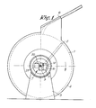
- FIG. 1 A type of centrifugal launcher to which the invention can be applied is shown diagrammatically in FIG. 1. It consists of a rotor 1 containing a cylindrical barrel 2, the whole being able to be driven in rotation for example by a turbine not shown.
- the rotor 1 has an open central zone in which extends a picking pallet 3 extending the barrel 2.
- the axis of the latter and the axis of rotation of the rotor 1 are two left-hand rights. More details of this construction can be found in Belgian Patent No. 886,482.
- a protective fairing 4 surrounds the rotor 1 and is mounted angularly adjustable on the support 5.
- the fairing 4 carries a rectifier device 6 intended to ensure a correct attitude of the projectiles after they have left the barrel 2.
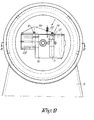
- the distributor 7 has the function of bringing projectiles 8 one by one in the trajectory of the pallet of picking 3 which supports them thus allowing their penetration into the barrel 2 under the effect of centrifugal force and therefore their ejection.
- the distributor 7 is constituted by a corridor element 9 fixed to a support 10 and leading to a transfer zone 11 provided in the latter.
- the corridor 9 is intended to receive a plurality of oblong shells 8 arranged side by side.
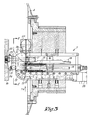
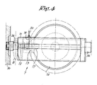
- a slide 12 capable of being displaced in one direction by the boss 13 of a cam 14 and, in the other direction, by return springs 15.
- This cam is driven by the drive shaft 16 of the rotor 1, via a pinion pin 17 driving a toothed ring 18 secured to the cam 14.
- a spring 22 urges the rocker towards a position in which the knife-stop opposes the return of the slide 12.
- the action of the spring 22 can be counteracted by an electromagnet 23 fixed to the support 10.
- the latter still carries a support element or anvil 24 situated opposite the slide 12 and at a distance from the entrance to the transfer zone 11 substantially equal to the caliber of the projectiles 8.
- the zone indicated at 25 in FIG. 3 is periodically crossed by the vane 3 of the barrel 2, during the rotation of the rotor 1.
- a jack 26 constantly pushes the projectiles 8 located in the corridor 9 towards the transfer zone 11.
- the operation of the distributor 7 is as follows.
- the "rest" position of the slide 12 is that closest to the anvil 24, position in which it is maintained by the knife-stop 19 as long as the electromagnet 23 is not energized.
- the slide 12 then opposes the exit of a projectile from the corridor 9 under the effect of the jack 26.
- the electromagnet 23 is briefly excited which causes the lifting of the knife-stop 19, the return of the slide 12 by the springs 15 and the entry of a projectile in the transfer zone 11.
- the boss 13 of the cam 14 immediately repels the slide 12 which itself repels the projectile which has reached the transfer zone 11 against the anvil 24 position in which it can be supported by said pallet 3 when the latter crosses zone 25.
- the frequency of the excitation of the electromagnet 23 determines the rate of fire.
- the maximum value of the latter is a function of the speed of rotation of the axis 16, the reduction ratio between the pinion 17 and the crown 18 and the number of bosses 13 provided on the cam 14.
- the supply of the electromagnet can be controlled by an AND gate circuit, the latter becoming conductive upon arrival of two signals: a firing order and a detection of the angular position of the barrel 2 relative to that of the fairing assembly 4 - rectifier 6 - distributor 7, the latter determining the increase in firing.
- an AND gate circuit the latter becomes conductive upon arrival of two signals: a firing order and a detection of the angular position of the barrel 2 relative to that of the fairing assembly 4 - rectifier 6 - distributor 7, the latter determining the increase in firing.
Landscapes
- Engineering & Computer Science (AREA)
- General Engineering & Computer Science (AREA)
- Centrifugal Separators (AREA)
- Toys (AREA)
- Unwinding Of Filamentary Materials (AREA)
- Feeding Of Articles To Conveyors (AREA)
- Casting Support Devices, Ladles, And Melt Control Thereby (AREA)
- Electromagnets (AREA)
- Recrystallisation Techniques (AREA)
Priority Applications (1)
| Application Number | Priority Date | Filing Date | Title |
|---|---|---|---|
| AT82201489T ATE23221T1 (de) | 1982-01-22 | 1982-11-24 | Geschossverteiler fuer eine zentrifugalschleuderwaffe. |
Applications Claiming Priority (2)
| Application Number | Priority Date | Filing Date | Title |
|---|---|---|---|
| BE2059552 | 1982-01-22 | ||
| BE2/59552A BE891864A (fr) | 1982-01-22 | 1982-01-22 | Distributeur de projectiles pour lanceur centrifuge |
Publications (3)
| Publication Number | Publication Date |
|---|---|
| EP0084688A2 true EP0084688A2 (de) | 1983-08-03 |
| EP0084688A3 EP0084688A3 (en) | 1984-07-11 |
| EP0084688B1 EP0084688B1 (de) | 1986-10-29 |
Family
ID=3865583
Family Applications (1)
| Application Number | Title | Priority Date | Filing Date |
|---|---|---|---|
| EP82201489A Expired EP0084688B1 (de) | 1982-01-22 | 1982-11-24 | Geschossverteiler für eine Zentrifugalschleuderwaffe |
Country Status (5)
| Country | Link |
|---|---|
| US (1) | US4607605A (de) |
| EP (1) | EP0084688B1 (de) |
| AT (1) | ATE23221T1 (de) |
| BE (1) | BE891864A (de) |
| DE (2) | DE3274011D1 (de) |
Families Citing this family (4)
| Publication number | Priority date | Publication date | Assignee | Title |
|---|---|---|---|---|
| US6520169B1 (en) | 2000-02-29 | 2003-02-18 | Trinamic Technologies, Llc | Weapon for centrifugal propulsion of projectiles |
| US10088263B2 (en) * | 2016-02-14 | 2018-10-02 | Paul Westmeyer | Acceleration and precision controlled ejection of mass |
| WO2017152219A1 (en) * | 2016-03-08 | 2017-09-14 | Utpal Bhattacharya | Projectile firing apparatus |
| US12044504B1 (en) * | 2021-07-15 | 2024-07-23 | Stephen Kennedy | Digitally controlled mobile ground launching fire retardant delivery system |
Family Cites Families (13)
| Publication number | Priority date | Publication date | Assignee | Title |
|---|---|---|---|---|
| GB191200373A (en) * | 1912-01-04 | 1913-04-04 | Arnold Goodwin | Improvements in or relating to Centrifugal Guns. |
| FR503486A (fr) * | 1917-06-19 | 1920-06-11 | Frisch & Cio A | Dispositif pour la projection successive d'une série de projectiles par action centrifuge |
| US1420660A (en) * | 1918-03-11 | 1922-06-27 | Centrifugal Gun Corp | Centrifugal gun |
| US1408137A (en) * | 1918-10-16 | 1922-02-28 | Arthur C Bunnell | Centrifugal gun |
| US1783053A (en) * | 1929-01-28 | 1930-11-25 | Baden-Powell Baden Fletc Smyth | Centrifugal gun |
| FR795554A (fr) * | 1934-12-22 | 1936-03-17 | Dispositif pour l'émission de projectiles, applicable plus particulièrement aux mitrailleuses et engins de tranchées | |
| FR869555A (fr) * | 1939-03-31 | 1942-02-05 | Lance projectiles-centrifuge | |
| US2311937A (en) * | 1941-12-19 | 1943-02-23 | Lloyd B Elliott | Target practicing device |
| US2391636A (en) * | 1944-03-20 | 1945-12-25 | Graham S Mcarthur | Gun |
| US3177862A (en) * | 1961-06-06 | 1965-04-13 | James G Allemann | Armament and fire control system for helicopters |
| US3548802A (en) * | 1968-07-22 | 1970-12-22 | Rudolph C Green | Pellet firing mechanism and fluid valve therefor |
| US3646888A (en) * | 1969-03-27 | 1972-03-07 | Explosive Tech | Aerodynamic directional grenade, launcher therefor and weapons system utilizing the same |
| BE886482A (fr) * | 1980-12-04 | 1981-06-04 | Rutten Leon | Rotor pour lanceur centrifuge. |
-
1982
- 1982-01-22 BE BE2/59552A patent/BE891864A/fr unknown
- 1982-11-24 DE DE8282201489T patent/DE3274011D1/de not_active Expired
- 1982-11-24 EP EP82201489A patent/EP0084688B1/de not_active Expired
- 1982-11-24 DE DE198282201489T patent/DE84688T1/de active Pending
- 1982-11-24 AT AT82201489T patent/ATE23221T1/de not_active IP Right Cessation
-
1983
- 1983-01-14 US US06/457,963 patent/US4607605A/en not_active Expired - Fee Related
Also Published As
| Publication number | Publication date |
|---|---|
| DE3274011D1 (en) | 1986-12-04 |
| DE84688T1 (de) | 1984-03-01 |
| BE891864A (fr) | 1982-07-22 |
| EP0084688B1 (de) | 1986-10-29 |
| US4607605A (en) | 1986-08-26 |
| ATE23221T1 (de) | 1986-11-15 |
| EP0084688A3 (en) | 1984-07-11 |
Similar Documents
| Publication | Publication Date | Title |
|---|---|---|
| EP1550837B1 (de) | Vorrichtung zur Entfaltung und Steuerung der Steuerflächen eines Projektils | |
| EP0053855B1 (de) | Rotor für eine Zentrifugalschleuderwaffe | |
| EP0084688B1 (de) | Geschossverteiler für eine Zentrifugalschleuderwaffe | |
| EP0362064A1 (de) | Automatische Schnellfeuer-Revolverwaffe | |
| SE459693B (sv) | Vapensystem med eldroersvapen i pansarfordon | |
| EP0580914A1 (de) | Tontaubenabschussvorrichtung für das Sportschiessen | |
| EP0536048B1 (de) | Mine zur Flächenverteidigung | |
| EP0518711B1 (de) | Mine mit Sensordrähten | |
| EP0571265A1 (de) | Munitionsladesystem zum Laden einer schwenkbaren Patronenlagers | |
| FR2691797A1 (fr) | Système de sécurité et d'armement pour sous-munition, en particulier pour sous-munition embarquée dans un obus cargo. | |
| FR2737293A1 (fr) | Systeme d'amorcage de la charge explosive d'une sous-munition embarquee dans un engin porteur | |
| FR2682749A1 (fr) | Systeme de chargement automatique d'une munition dans la chambre du tube d'un canon, en particulier du canon d'un char, et char equipe d'un tel dispositif. | |
| EP0016701A1 (de) | Sicherheitsvorrichtung für pyrotechnische Elemente | |
| FR2718837A1 (fr) | Arme à feu automatique multitubes de petit ou moyen calibre du type GATLING, notamment destinée au tir de munitions télescopées. | |
| EP1034411A1 (de) | Generator zur pyrotechnischen erzeugung von akustischen druckwellen zum schutz von schiffen und unterseeboten | |
| EP0067762A1 (de) | Einrichtung zum Überführen länglicher Gegenstände in einen Förderkanal | |
| FR2518737A1 (fr) | Systeme de defense de zone a grenade gyroplanante | |
| EP3910280B1 (de) | Vorrichtung zur erkennung des fehlens einer mechanischen barriere für einen flugkörper und flugkörper mit einer solchen vorrichtung | |
| FR2682468A1 (fr) | Projectile pour une arme antichar pour attaquer un char en haut. | |
| EP0053421B1 (de) | Geschoss für eine Zentrifugalschleuderwaffe | |
| EP3742102B1 (de) | Auswurfvorrichtung für kettenglieder von munitionsauswurfbändern | |
| FR2563622A1 (fr) | Dispositif de securite et d'armement pour engins explosifs | |
| EP0664430B1 (de) | Munitionsladevorrichtung für eine in einem Panzerturm angeordnete Rohrwaffe | |
| SE452365B (sv) | Sekringsanordning for ammunitionstendror | |
| FR2468948A1 (fr) | Dispositif de visualisation du nombre de coups tires avec une munition d'exercice |
Legal Events
| Date | Code | Title | Description |
|---|---|---|---|
| PUAI | Public reference made under article 153(3) epc to a published international application that has entered the european phase |
Free format text: ORIGINAL CODE: 0009012 |
|
| AK | Designated contracting states |
Designated state(s): AT CH DE FR GB IT LI LU NL SE |
|
| ITCL | It: translation for ep claims filed |
Representative=s name: DR. ING. A. RACHELI & C. |
|
| TCAT | At: translation of patent claims filed | ||
| TCNL | Nl: translation of patent claims filed | ||
| DET | De: translation of patent claims | ||
| PUAL | Search report despatched |
Free format text: ORIGINAL CODE: 0009013 |
|
| AK | Designated contracting states |
Designated state(s): AT CH DE FR GB IT LI LU NL SE |
|
| 17P | Request for examination filed |
Effective date: 19841002 |
|
| GRAA | (expected) grant |
Free format text: ORIGINAL CODE: 0009210 |
|
| AK | Designated contracting states |
Kind code of ref document: B1 Designated state(s): AT CH DE FR GB IT LI LU NL SE |
|
| REF | Corresponds to: |
Ref document number: 23221 Country of ref document: AT Date of ref document: 19861115 Kind code of ref document: T |
|
| PG25 | Lapsed in a contracting state [announced via postgrant information from national office to epo] |
Ref country code: LU Free format text: LAPSE BECAUSE OF NON-PAYMENT OF DUE FEES Effective date: 19861130 |
|
| REF | Corresponds to: |
Ref document number: 3274011 Country of ref document: DE Date of ref document: 19861204 |
|
| ITF | It: translation for a ep patent filed | ||
| PLBE | No opposition filed within time limit |
Free format text: ORIGINAL CODE: 0009261 |
|
| STAA | Information on the status of an ep patent application or granted ep patent |
Free format text: STATUS: NO OPPOSITION FILED WITHIN TIME LIMIT |
|
| 26N | No opposition filed | ||
| PGFP | Annual fee paid to national office [announced via postgrant information from national office to epo] |
Ref country code: FR Payment date: 19891120 Year of fee payment: 8 |
|
| PGFP | Annual fee paid to national office [announced via postgrant information from national office to epo] |
Ref country code: SE Payment date: 19891121 Year of fee payment: 8 |
|
| PGFP | Annual fee paid to national office [announced via postgrant information from national office to epo] |
Ref country code: CH Payment date: 19891124 Year of fee payment: 8 |
|
| PGFP | Annual fee paid to national office [announced via postgrant information from national office to epo] |
Ref country code: AT Payment date: 19891127 Year of fee payment: 8 |
|
| ITTA | It: last paid annual fee | ||
| PGFP | Annual fee paid to national office [announced via postgrant information from national office to epo] |
Ref country code: NL Payment date: 19891130 Year of fee payment: 8 Ref country code: GB Payment date: 19891130 Year of fee payment: 8 |
|
| PGFP | Annual fee paid to national office [announced via postgrant information from national office to epo] |
Ref country code: DE Payment date: 19900130 Year of fee payment: 8 |
|
| PGFP | Annual fee paid to national office [announced via postgrant information from national office to epo] |
Ref country code: LU Payment date: 19900608 Year of fee payment: 8 |
|
| PG25 | Lapsed in a contracting state [announced via postgrant information from national office to epo] |
Ref country code: GB Effective date: 19901124 Ref country code: AT Effective date: 19901124 |
|
| PG25 | Lapsed in a contracting state [announced via postgrant information from national office to epo] |
Ref country code: SE Effective date: 19901125 |
|
| PG25 | Lapsed in a contracting state [announced via postgrant information from national office to epo] |
Ref country code: LI Effective date: 19901130 Ref country code: CH Effective date: 19901130 |
|
| PG25 | Lapsed in a contracting state [announced via postgrant information from national office to epo] |
Ref country code: NL Effective date: 19910601 |
|
| NLV4 | Nl: lapsed or anulled due to non-payment of the annual fee | ||
| GBPC | Gb: european patent ceased through non-payment of renewal fee | ||
| PG25 | Lapsed in a contracting state [announced via postgrant information from national office to epo] |
Ref country code: FR Effective date: 19910731 |
|
| REG | Reference to a national code |
Ref country code: CH Ref legal event code: PL |
|
| PG25 | Lapsed in a contracting state [announced via postgrant information from national office to epo] |
Ref country code: DE Effective date: 19910801 |
|
| REG | Reference to a national code |
Ref country code: CH Ref legal event code: AUV Free format text: LE BREVET CI-DESSUS EST TOMBE EN DECHEANCE FAUTE DE PAIEMENT, DE LA 9E ANNUITE. |
|
| REG | Reference to a national code |
Ref country code: FR Ref legal event code: ST |
|
| EUG | Se: european patent has lapsed |
Ref document number: 82201489.0 Effective date: 19910705 |