EP0084820A2 - Procédé pour le séchage des copeaux de betterave à sucre et dispositif pour l'application du procédé - Google Patents
Procédé pour le séchage des copeaux de betterave à sucre et dispositif pour l'application du procédé Download PDFInfo
- Publication number
- EP0084820A2 EP0084820A2 EP83100268A EP83100268A EP0084820A2 EP 0084820 A2 EP0084820 A2 EP 0084820A2 EP 83100268 A EP83100268 A EP 83100268A EP 83100268 A EP83100268 A EP 83100268A EP 0084820 A2 EP0084820 A2 EP 0084820A2
- Authority
- EP
- European Patent Office
- Prior art keywords
- drying
- chips
- air inlet
- drying air
- inlet pipe
- Prior art date
- Legal status (The legal status is an assumption and is not a legal conclusion. Google has not performed a legal analysis and makes no representation as to the accuracy of the status listed.)
- Granted
Links
Images

Classifications
-
- F—MECHANICAL ENGINEERING; LIGHTING; HEATING; WEAPONS; BLASTING
- F26—DRYING
- F26B—DRYING SOLID MATERIALS OR OBJECTS BY REMOVING LIQUID THEREFROM
- F26B3/00—Drying solid materials or objects by processes involving the application of heat
- F26B3/02—Drying solid materials or objects by processes involving the application of heat by convection, i.e. heat being conveyed from a heat source to the materials or objects to be dried by a gas or vapour, e.g. air
- F26B3/06—Drying solid materials or objects by processes involving the application of heat by convection, i.e. heat being conveyed from a heat source to the materials or objects to be dried by a gas or vapour, e.g. air the gas or vapour flowing through the materials or objects to be dried
-
- F—MECHANICAL ENGINEERING; LIGHTING; HEATING; WEAPONS; BLASTING
- F26—DRYING
- F26B—DRYING SOLID MATERIALS OR OBJECTS BY REMOVING LIQUID THEREFROM
- F26B11/00—Machines or apparatus for drying solid materials or objects with movement which is non-progressive
- F26B11/12—Machines or apparatus for drying solid materials or objects with movement which is non-progressive in stationary drums or other mainly-closed receptacles with moving stirring devices
- F26B11/16—Machines or apparatus for drying solid materials or objects with movement which is non-progressive in stationary drums or other mainly-closed receptacles with moving stirring devices the stirring device moving in a vertical or steeply-inclined plane
-
- F—MECHANICAL ENGINEERING; LIGHTING; HEATING; WEAPONS; BLASTING
- F26—DRYING
- F26B—DRYING SOLID MATERIALS OR OBJECTS BY REMOVING LIQUID THEREFROM
- F26B17/00—Machines or apparatus for drying materials in loose, plastic, or fluidised form, e.g. granules, staple fibres, with progressive movement
- F26B17/18—Machines or apparatus for drying materials in loose, plastic, or fluidised form, e.g. granules, staple fibres, with progressive movement with movement performed by rotating helical blades or other rotary conveyors which may be heated moving materials in stationary chambers, e.g. troughs
- F26B17/20—Machines or apparatus for drying materials in loose, plastic, or fluidised form, e.g. granules, staple fibres, with progressive movement with movement performed by rotating helical blades or other rotary conveyors which may be heated moving materials in stationary chambers, e.g. troughs the axis of rotation being horizontal or slightly inclined
- F26B17/205—Machines or apparatus for drying materials in loose, plastic, or fluidised form, e.g. granules, staple fibres, with progressive movement with movement performed by rotating helical blades or other rotary conveyors which may be heated moving materials in stationary chambers, e.g. troughs the axis of rotation being horizontal or slightly inclined with multiple chambers, e.g. troughs, in superimposed arrangement
Definitions
- the invention relates to a method for drying sugar beet chips, namely wet or pressed chips, drying air being blown along a conveyor line through this chip, and device for carrying out this method.
- the oil consumption per day is approx. 70 to 80 tons for the drying process alone.
- Financially very expensive cylinder presses have managed to squeeze approx. 5% water out of the resulting wet chips and thus contribute to the dry matter content Start drying by 5%.
- a cylinder press can process a maximum of 10 tons per hour.
- the squeezed wet chips are referred to as so-called press chips with a share of approx. 25% dry matter and 75% water.
- press chips allow the drying temperature in the large drying drums to be reduced by 200 ° C. This corresponds to an oil saving of approx. 15% per day.
- the aim is to use the waste heat in a sugar factory for intermediate drying.
- the warm exhaust air that was previously led out to the roof and the heat from cooking broth and flue gas are obtained via heat exchangers.
- the flue gas has a temperature of 200 ° C and a relative humidity of approx. 0.5%.
- Per 10 tons per hour pressed chips is characterized a hot air volume of approximately 400,000 m 3 with a relative humidity of 25% and a temperature of 90 0 C is available. This amount of hot air is forced through huge perforated belts on which the press chips lie.
- the dwell time of the air in the shredded material is only approx. 0.2 sec due to the high air speed. To increase the dry matter from 25 to 70%, a run and dwell time of the shredded material on the belts of approx. 2 hours is required .
- the object is achieved in that the drying air, which is kept at an elevated temperature, is pressed through the chips from inside to outside with a rotating air jet in a drying section, and the chips are thereby turbulently moved in all-round air contact.
- a drying air stream which is circulating around the central axis of the drying section and blown from the inside out is pressed through the chips.
- the sugar beet chips are placed under sharp pressure in alternation and then relaxed again. This allows the sugar beet pulp to work within itself and release moisture.
- This dewatering process can only work with waste heat from the factory, be it from the boilers or from other hot rooms. Only waste heat is used and exploited. In addition, another waste product from the factory, namely the flue gas, can be used for drying.
- a paddle rotor can be rotated about the drying air inlet pipe and carries paddles which further convey the chips along the drying space between the casing pipe and the drying air inlet pipe.
- the paddle rotor and the drying air inlet pipe can be rotated in opposite directions.
- screw paddles are arranged directly on the drying air inlet pipe, which rotate with the inlet pipe and axially convey the chips along the drying space between the stationary casing pipe and the drying air inlet pipe.
- the drying space between the drying air inlet pipe and the jacket pipe is filled to about 50% with the chips.
- the proportion of shredded material to air is approximately 50:50%.
- the volume then inflates to about the full drying space. Due to the limitation of the perforated air outlet, a heat accumulation practically arises within the device. This is the inside through the schnitzel Drying air pressed into the drying room is held in the drying room.
- the size of the air outlet must be such that only as much air can flow out of the jacket tube as is supplied through the inlet tube.
- the inlet pipe outlet openings are designed as slots which extend in a line along the drying air inlet pipe over the entire length of the drying chamber. Due to the formation of slots lined up in a line, the drying air is always only regionally blown into the chips and pushed through them when the inlet pipe rotates, as a result of which the preferred constant change of pressure load and pressure relief on the chips comes about. According to a further embodiment of the invention, it is provided that the jacket tube outlet extends along the top of the jacket tube over the entire length of the drying room.
- the casing tube outlet is covered by a grille on which the paddles or wipers of the paddle rotor slide along the inside in a cleaning manner.
- the slots in the inlet pipe are also covered by a grid.
- the grids consist of a fiberglass mesh braid coated with Teflon, which spans the jacket tube outlet or the slots in the inlet tube. At With a mesh size of approx. 4 mm, the open grid area is approx. 70%.
- the mesh is heat-resistant and tensile.
- the mesh has a special and essential meaning for the function of the device.
- the advantage of attaching the mesh to the jacket pipe air outlet is that the air that is blown in accumulates somewhat in the drying room and that the air outlet is uniform despite the rotation of the air injection.
- a material layer is deposited on the inner side of the mesh, which is kept to a thickness of approx. 6 mm by constant removal either by means of the surrounding paddles or the wipers.
- the meshwork acts as an air filter.
- the system works dust-free, and the oversized dust separators that would otherwise be necessary due to the large air flow rates can be eliminated.
- the mesh On the side of the slots on the inlet pipe, the mesh has the task of preventing the chips material from falling back into the air duct if the system suddenly comes to a standstill, for example due to a power failure.
- a heat-insulating housing enclosing the drying unit comprising the jacket tube and the drying air inlet tube, it can be ensured that the elevated temperature is maintained within the device. This also allows the treatment time as needed be extended. This can be done in such a way that the drying unit, which is surrounded by the casing tube and is provided with the drying air inlet tube, is arranged in a heat-insulating housing.
- a plurality of drying units are preferably arranged one above the other. The chips are passed on from one drying unit to another drying unit.
- the hot air stays in the shredded material for approx. 2 seconds.
- a runtime of the shredded material can be 30 minutes if the hot air is saturated to approx. 92%.
- the dwell time of the hot air within the shredded material is 10 times as long as with the previous intermediate belt drying.
- the electricity consumption for fans can be reduced from approx. 1400 kW per hour to approx. 800 kW per hour in a planned 60-ton system.
- Using the method and the device according to the invention results in an oil saving of about 5 to 6 million tons in a medium-sized sugar factory with about 60 tons of pressed chips per hour in a campaign of about 2.5 months.
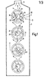
- a heat-insulating housing 3 shown in FIG. 1 four drying units 5 are arranged one above the other.
- the housing 3 consists of plastic plates and is therefore well heat-insulating. At the same time, the housing 3 also serves to guide the air.
- the drying units 5 are composed of several parts.
- the drying units 5 are each surrounded on the outside by a jacket tube 7 which is provided with a perforated outlet 11 which extends along its top 9.
- a paddle rotor 13 rotates within the casing tube 7.
- This paddle rotor 13 consists, for example, of steel band rotor rims 15, which are connected to one another via longitudinal struts 16, and bearing rings 17.
- Paddles 19 are provided on the longitudinal struts 16 for longitudinally conveying the chips and strippers 20 for stripping Dust and chips from the perforated outlet 11 are arranged.
- the paddles 19 point inward from the longitudinal struts 16 to the center of the tube.
- the wipers 20, which are arranged on the longitudinal struts 16, extend to the outside (approx. 2 mm) in front of the central tube 7.
- the bearing rings 17 are supported on a drying air inlet pipe 21 through which drying air is introduced into the interior of the drying unit 5.
- the drying air inlet tube 21, which rotates counter to the paddle rotor 13 during operation, is provided with slots 23 which extend along a longitudinal line 29 and from which the drying air (for example approximately 50,000 to 100,000 m 3 / h and drying unit is pressed into the jacket tube 7) full length covered with a heat-resistant, tensile grid 24, which is shown and described in more detail in FIGS. 2-4.
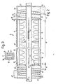
- FIGS. 2 to 4 Details of a drying unit designed according to the invention can be seen from FIGS. 2 to 4.
- the casing tube 7 is closed at its head ends 25 by means of lids 27 (FIGS. 2 and 4).
- the lids 27 also serve to mount the drying air inlet tube 21. Storage and drive of the drying air inlet tube 21 are not explained in detail.
- the designer uses the usual common constructions. The same applies to the paddle rotor 13, which can be rotated by a drive (not explained in more detail), for example, via an external toothed ring 28.
- the paddles 19 convey the chips 44 surrounding the drying air inlet tube 21 in the drying unit according to FIG. 2 in the direction of a Arrow 45 along the drying unit.
- the paddles 19 give the chips a turbulent movement in accordance with their degree setting in relation to the conveying direction and rotational speed.
- the outlet 11 from the jacket tube can be seen in FIG. 2 on the top 9 of the jacket tube 7.
- This jacket tube outlet 11 consists of a wide slot-shaped opening.
- a grating 57 is stretched over the tubular casing outlet 11.
- This grating 57 preferably consists of a fiberglass mesh braid coated with Teflon. Other grid materials are also conceivable.
- the grid 57 is fixed along the outlet opening edges on the top 9 of the casing tube 7, for example with holding strips 59.
- the mesh for example, has a mesh size of approx. 4 mm and has 70% open area. It is heat resistant and tensile.
- FIG 3 shows a top view III of a section of the casing tube 7 according to FIGS. 2 and 4.
- the outlet 11 is clearly covered by the grating 57, between the meshes of the grating 57 Form blow-through openings 61. It has been shown that soaring chips and dust do not clog the blow-through openings if, for example, four wipers 20 constantly strip off the layer consisting of chips and dust particles, which are deposited on the grid, and keep the residues of the same thickness of about 6 mm. This leads to an almost dust-free air outlet without pressure fluctuations.
- the chips are each poured into a drying unit, for example into the top drying unit 5 according to FIG. 2, from above; they move turbulently through this top drying unit in the direction of arrow 45 and leave it through outlet 55. The chips then fall into the inlet of the drying unit, which conveys in the opposite direction and lies below. This means that continuous conveying operations are carried out in alternating directions.
- the jacket tube 7 of the second lowermost drying unit is flushed with the warm air that flows out of the jacket tube 7 of the lowest drying unit. All blown out warm air flows in the direction of arrows 69 and flows around all higher-lying drying units 5. This means that all higher-lying jacket pipes 7 are also heated from the outside, and the heat cannot escape from the inside of these drying units. The warm air is thus concentrated in a confined space and in particular in the drying units. The heat introduced, apart from the heat escaping through the exhaust air duct 71, remains retained within the device. Only the additional Energy required to rotate the drying air inlet pipes 21 and the paddle rotors 13. How out 1, the inlet tube 21 and the rotor 13 rotate in opposite directions. The opposite directions are indicated by the arrows 73 for the drying air inlet tube 21 and 75 for the paddle rotor.
- FIG. 4 shows a modification of the drying unit 5 according to FIG. 2.
- the drying unit 105 according to FIG. 4 largely corresponds to that according to FIGS. 2 and 3.
- the same parts are provided with the same reference numerals.
- the drying air inlet tube 121 rotates.
- a plurality of screw flights 49 are again fastened on the drying air inlet tube 121 for introducing the chips into the drying space 41 (area B) and sealing them off.
- area C of the material outlet 55 as in the embodiment according to FIG. 2, a screw flight is omitted, as a result of which a plug of material forms for additional sealing.
- a paddle screw replaces the paddle rotor13.
- screw paddles 119 are arranged on the drying air inlet pipe 121. These screw paddles 119 extend from the inlet pipe 121 outwards to just before the inner wall of the casing tube 7 or up to about 6 mm in front of the mesh, so as to also open the grid openings 61 by stripping by means of the screw paddles 119.
- the rotating drying air inlet pipe 121 with its rotating screw paddles, ensures the material is conveyed in the direction of the arrow 45 and, depending on its degree setting with respect to the direction of conveyance and rotational speed, additionally turbulent swirling of the chips.
- the material flow is moved axially by means of the paddles and swirled turbulently.
- the drying air blows radially into the drying space 41 through the inlet slots 23, with a circulating blow jet.
- the paddles keep the schnitzel turbulent in suspension. In this way, there is an all-round air contact of the chips.
- the contact time between the drying air and the chips is approx. 2 seconds.
- the paddles are preferably arranged along one or more jacket lines, which loop around the jacket tube 7 once over the length of the drying space 41 (area B).
Landscapes
- Engineering & Computer Science (AREA)
- Mechanical Engineering (AREA)
- General Engineering & Computer Science (AREA)
- Life Sciences & Earth Sciences (AREA)
- Microbiology (AREA)
- Drying Of Solid Materials (AREA)
- Storage Of Fruits Or Vegetables (AREA)
- Seasonings (AREA)
- Preparation Of Fruits And Vegetables (AREA)
- Apparatuses For Bulk Treatment Of Fruits And Vegetables And Apparatuses For Preparing Feeds (AREA)
Priority Applications (3)
| Application Number | Priority Date | Filing Date | Title |
|---|---|---|---|
| AT83100268T ATE33070T1 (de) | 1982-01-22 | 1983-01-14 | Verfahren zum trocknen von zuckerruebenschnitzeln und vorrichtung zur durchfuehrung dieses verfahrens. |
| PCT/DE1984/000007 WO1984002768A1 (fr) | 1983-01-14 | 1984-01-16 | Procede de sechage complet de cossettes de betteraves sucrieres et installation pour executer le procede |
| JP59500611A JPS60500459A (ja) | 1983-01-14 | 1984-01-16 | 砂糖大根チツプの完全乾燥法及びこの方法を実施する装置 |
Applications Claiming Priority (2)
| Application Number | Priority Date | Filing Date | Title |
|---|---|---|---|
| DE19823201843 DE3201843A1 (de) | 1982-01-22 | 1982-01-22 | "verfahren und vorrichtung zum trocknen von zuckerruebenschnitzeln" |
| DE3201843 | 1982-01-22 |
Publications (3)
| Publication Number | Publication Date |
|---|---|
| EP0084820A2 true EP0084820A2 (fr) | 1983-08-03 |
| EP0084820A3 EP0084820A3 (en) | 1984-09-05 |
| EP0084820B1 EP0084820B1 (fr) | 1988-03-16 |
Family
ID=6153594
Family Applications (1)
| Application Number | Title | Priority Date | Filing Date |
|---|---|---|---|
| EP83100268A Expired EP0084820B1 (fr) | 1982-01-22 | 1983-01-14 | Procédé pour le séchage des copeaux de betterave à sucre et dispositif pour l'application du procédé |
Country Status (3)
| Country | Link |
|---|---|
| EP (1) | EP0084820B1 (fr) |
| AT (1) | ATE33070T1 (fr) |
| DE (2) | DE3201843A1 (fr) |
Cited By (1)
| Publication number | Priority date | Publication date | Assignee | Title |
|---|---|---|---|---|
| CN110030809A (zh) * | 2019-04-17 | 2019-07-19 | 焦作大学 | 一种植物茎部切片干燥装置 |
Families Citing this family (1)
| Publication number | Priority date | Publication date | Assignee | Title |
|---|---|---|---|---|
| CN109916165A (zh) * | 2019-03-01 | 2019-06-21 | 广州市盈夏机械技术有限公司 | 一种节能环保多功能双立罐滚筒烘干机 |
Family Cites Families (6)
| Publication number | Priority date | Publication date | Assignee | Title |
|---|---|---|---|---|
| DE165644C (fr) * | ||||
| DE35176C (de) * | 1885-08-15 | 1886-04-05 | E. BACH in Leipzig, Alexanderstr. 38, Hof II | Trockenapparat |
| US1416960A (en) * | 1921-08-15 | 1922-05-23 | Ladisch Karl | Drier |
| US2019668A (en) * | 1933-07-03 | 1935-11-05 | Jesse J Fowler | Drier |
| US3494049A (en) * | 1968-03-18 | 1970-02-10 | Universal Oil Prod Co | Apparatus for fluid treatment of granular material |
| DE2143462B2 (de) * | 1971-08-31 | 1973-09-27 | Karl 6080 Gross-Gerau Kron | Gerät zur kontinuierlichen Trocknung landwirtschaftlicher Erzeugnisse |
-
1982
- 1982-01-22 DE DE19823201843 patent/DE3201843A1/de not_active Ceased
-
1983
- 1983-01-14 AT AT83100268T patent/ATE33070T1/de not_active IP Right Cessation
- 1983-01-14 DE DE8383100268T patent/DE3376031D1/de not_active Expired
- 1983-01-14 EP EP83100268A patent/EP0084820B1/fr not_active Expired
Cited By (1)
| Publication number | Priority date | Publication date | Assignee | Title |
|---|---|---|---|---|
| CN110030809A (zh) * | 2019-04-17 | 2019-07-19 | 焦作大学 | 一种植物茎部切片干燥装置 |
Also Published As
| Publication number | Publication date |
|---|---|
| ATE33070T1 (de) | 1988-04-15 |
| EP0084820A3 (en) | 1984-09-05 |
| EP0084820B1 (fr) | 1988-03-16 |
| DE3376031D1 (en) | 1988-04-21 |
| DE3201843A1 (de) | 1983-08-04 |
Similar Documents
| Publication | Publication Date | Title |
|---|---|---|
| DE3142985C2 (fr) | ||
| DE3248384A1 (de) | Einrichtung zur trocknung von feststoffen | |
| DE2741710A1 (de) | Verfahren und vorrichtung zum trennen von feststoffen und fluessigkeiten aus einer suspension | |
| DE3518323A1 (de) | Verfahren und vorrichtung zum trocknen von klaerschlamm | |
| DE2649633A1 (de) | Verfahren und vorrichtung zum behandeln von fein verteiltem schuettgut mit gas ohne ueberdruck | |
| DE2635079A1 (de) | Getreidetrockner | |
| DE212018000309U1 (de) | Förderschnecke für Vorrichtung zur Entsorgung von Nahrungsmittelabfällen | |
| DE2820454B2 (de) | Anlage zur Kühlung und Trennung von Abgüssen und Formsand | |
| WO2010046195A2 (fr) | Extrusion extractive d'un produit de tabac | |
| EP1147805B1 (fr) | Procédé pour disperser une pulpe de fibres de papier et installation pour l'exécution du procédé | |
| DE2611853A1 (de) | Verfahren zum trocknen landwirtschaftlicher futtermittel und schlammartiger materialien | |
| DE2241264A1 (de) | Trockentrommel | |
| DE2248051A1 (de) | Verfahren zum kontinuierlichen trocknen von tropfnassen, koernigen und/oder stueckigen guetern und vorrichtung zur durchfuehrung des verfahrens | |
| DE1411283A1 (de) | Siebanordnung in zylindrischen Behaeltern fuer Zellstoffbrei | |
| DE202023105516U1 (de) | Kohleblöckezerkleinerungsvorrichtung für thermisches Kraftwerk | |
| DE2301464A1 (de) | Verfahren und vorrichtung zum einstellen von betriebsparametern eines durch eine leitung fliessenden fluids | |
| EP0084820A2 (fr) | Procédé pour le séchage des copeaux de betterave à sucre et dispositif pour l'application du procédé | |
| DE4121223A1 (de) | Verfahren zur aufbereitung von schlaemmen unterschiedlicher konsistenz und anlage zur durchfuehrung des verfahrens | |
| EP0611937A1 (fr) | Malaxeur-sécheur | |
| DE2111380B2 (de) | Vorrichtung zum pilieren von seifen oder aehnlichen, pastenartigen massen | |
| WO1984002768A1 (fr) | Procede de sechage complet de cossettes de betteraves sucrieres et installation pour executer le procede | |
| EP2437016B1 (fr) | Tambour de séchage de déchets ménagers et procédé de séchage de déchets ménagers | |
| DE2745179A1 (de) | Verfahren und vorrichtung zum chargenweisen mischen, trocknen und/oder granulieren von schuettguetern | |
| DE1461012B2 (de) | Vorrichtung zum zerfasern von papierstoff | |
| DE19542301B4 (de) | Verfahren und Einrichtung zum Trocknen von schlammartigem Trockengut, insbesondere Klärschlamm |
Legal Events
| Date | Code | Title | Description |
|---|---|---|---|
| PUAI | Public reference made under article 153(3) epc to a published international application that has entered the european phase |
Free format text: ORIGINAL CODE: 0009012 |
|
| AK | Designated contracting states |
Designated state(s): AT BE CH DE FR GB IT LI LU NL SE |
|
| RAP1 | Party data changed (applicant data changed or rights of an application transferred) |
Owner name: KAMMER, UTE |
|
| PUAL | Search report despatched |
Free format text: ORIGINAL CODE: 0009013 |
|
| AK | Designated contracting states |
Designated state(s): AT BE CH DE FR GB IT LI LU NL SE |
|
| 17P | Request for examination filed |
Effective date: 19850302 |
|
| 17Q | First examination report despatched |
Effective date: 19870630 |
|
| GRAA | (expected) grant |
Free format text: ORIGINAL CODE: 0009210 |
|
| AK | Designated contracting states |
Kind code of ref document: B1 Designated state(s): AT BE CH DE FR GB IT LI LU NL SE |
|
| REF | Corresponds to: |
Ref document number: 33070 Country of ref document: AT Date of ref document: 19880415 Kind code of ref document: T |
|
| REF | Corresponds to: |
Ref document number: 3376031 Country of ref document: DE Date of ref document: 19880421 |
|
| GBT | Gb: translation of ep patent filed (gb section 77(6)(a)/1977) | ||
| ITF | It: translation for a ep patent filed | ||
| ET | Fr: translation filed | ||
| PLBE | No opposition filed within time limit |
Free format text: ORIGINAL CODE: 0009261 |
|
| STAA | Information on the status of an ep patent application or granted ep patent |
Free format text: STATUS: NO OPPOSITION FILED WITHIN TIME LIMIT |
|
| PGFP | Annual fee paid to national office [announced via postgrant information from national office to epo] |
Ref country code: FR Payment date: 19890127 Year of fee payment: 7 |
|
| PGFP | Annual fee paid to national office [announced via postgrant information from national office to epo] |
Ref country code: DE Payment date: 19890130 Year of fee payment: 7 Ref country code: CH Payment date: 19890130 Year of fee payment: 7 |
|
| ITTA | It: last paid annual fee | ||
| PG25 | Lapsed in a contracting state [announced via postgrant information from national office to epo] |
Ref country code: LU Free format text: LAPSE BECAUSE OF NON-PAYMENT OF DUE FEES Effective date: 19890131 |
|
| PGFP | Annual fee paid to national office [announced via postgrant information from national office to epo] |
Ref country code: SE Payment date: 19890131 Year of fee payment: 7 Ref country code: NL Payment date: 19890131 Year of fee payment: 11 Ref country code: LU Payment date: 19890131 Year of fee payment: 7 Ref country code: AT Payment date: 19890131 Year of fee payment: 7 |
|
| PGFP | Annual fee paid to national office [announced via postgrant information from national office to epo] |
Ref country code: GB Payment date: 19890228 Year of fee payment: 7 |
|
| 26N | No opposition filed | ||
| PGFP | Annual fee paid to national office [announced via postgrant information from national office to epo] |
Ref country code: BE Payment date: 19890308 Year of fee payment: 7 |
|
| PG25 | Lapsed in a contracting state [announced via postgrant information from national office to epo] |
Ref country code: GB Effective date: 19900114 Ref country code: AT Effective date: 19900114 |
|
| PG25 | Lapsed in a contracting state [announced via postgrant information from national office to epo] |
Ref country code: SE Effective date: 19900115 |
|
| PG25 | Lapsed in a contracting state [announced via postgrant information from national office to epo] |
Ref country code: LI Effective date: 19900131 Ref country code: CH Effective date: 19900131 Ref country code: BE Effective date: 19900131 |
|
| BERE | Be: lapsed |
Owner name: KAMMER UTE Effective date: 19900131 |
|
| PG25 | Lapsed in a contracting state [announced via postgrant information from national office to epo] |
Ref country code: NL Effective date: 19900801 |
|
| GBPC | Gb: european patent ceased through non-payment of renewal fee | ||
| NLV4 | Nl: lapsed or anulled due to non-payment of the annual fee | ||
| PG25 | Lapsed in a contracting state [announced via postgrant information from national office to epo] |
Ref country code: FR Effective date: 19900928 |
|
| REG | Reference to a national code |
Ref country code: CH Ref legal event code: PL |
|
| PG25 | Lapsed in a contracting state [announced via postgrant information from national office to epo] |
Ref country code: DE Effective date: 19901002 |
|
| REG | Reference to a national code |
Ref country code: FR Ref legal event code: ST |
|
| EUG | Se: european patent has lapsed |
Ref document number: 83100268.8 Effective date: 19901106 |