EP0084820A2 - Verfahren zum Trocknen von Zuckerrübenschnitzeln und Vorrichtung zur Durchführung dieses Verfahrens - Google Patents
Verfahren zum Trocknen von Zuckerrübenschnitzeln und Vorrichtung zur Durchführung dieses Verfahrens Download PDFInfo
- Publication number
- EP0084820A2 EP0084820A2 EP83100268A EP83100268A EP0084820A2 EP 0084820 A2 EP0084820 A2 EP 0084820A2 EP 83100268 A EP83100268 A EP 83100268A EP 83100268 A EP83100268 A EP 83100268A EP 0084820 A2 EP0084820 A2 EP 0084820A2
- Authority
- EP
- European Patent Office
- Prior art keywords
- drying
- chips
- air inlet
- drying air
- inlet pipe
- Prior art date
- Legal status (The legal status is an assumption and is not a legal conclusion. Google has not performed a legal analysis and makes no representation as to the accuracy of the status listed.)
- Granted
Links
Images

Classifications
-
- F—MECHANICAL ENGINEERING; LIGHTING; HEATING; WEAPONS; BLASTING
- F26—DRYING
- F26B—DRYING SOLID MATERIALS OR OBJECTS BY REMOVING LIQUID THEREFROM
- F26B3/00—Drying solid materials or objects by processes involving the application of heat
- F26B3/02—Drying solid materials or objects by processes involving the application of heat by convection, i.e. heat being conveyed from a heat source to the materials or objects to be dried by a gas or vapour, e.g. air
- F26B3/06—Drying solid materials or objects by processes involving the application of heat by convection, i.e. heat being conveyed from a heat source to the materials or objects to be dried by a gas or vapour, e.g. air the gas or vapour flowing through the materials or objects to be dried
-
- F—MECHANICAL ENGINEERING; LIGHTING; HEATING; WEAPONS; BLASTING
- F26—DRYING
- F26B—DRYING SOLID MATERIALS OR OBJECTS BY REMOVING LIQUID THEREFROM
- F26B11/00—Machines or apparatus for drying solid materials or objects with movement which is non-progressive
- F26B11/12—Machines or apparatus for drying solid materials or objects with movement which is non-progressive in stationary drums or other mainly-closed receptacles with moving stirring devices
- F26B11/16—Machines or apparatus for drying solid materials or objects with movement which is non-progressive in stationary drums or other mainly-closed receptacles with moving stirring devices the stirring device moving in a vertical or steeply-inclined plane
-
- F—MECHANICAL ENGINEERING; LIGHTING; HEATING; WEAPONS; BLASTING
- F26—DRYING
- F26B—DRYING SOLID MATERIALS OR OBJECTS BY REMOVING LIQUID THEREFROM
- F26B17/00—Machines or apparatus for drying materials in loose, plastic, or fluidised form, e.g. granules, staple fibres, with progressive movement
- F26B17/18—Machines or apparatus for drying materials in loose, plastic, or fluidised form, e.g. granules, staple fibres, with progressive movement with movement performed by rotating helical blades or other rotary conveyors which may be heated moving materials in stationary chambers, e.g. troughs
- F26B17/20—Machines or apparatus for drying materials in loose, plastic, or fluidised form, e.g. granules, staple fibres, with progressive movement with movement performed by rotating helical blades or other rotary conveyors which may be heated moving materials in stationary chambers, e.g. troughs the axis of rotation being horizontal or slightly inclined
- F26B17/205—Machines or apparatus for drying materials in loose, plastic, or fluidised form, e.g. granules, staple fibres, with progressive movement with movement performed by rotating helical blades or other rotary conveyors which may be heated moving materials in stationary chambers, e.g. troughs the axis of rotation being horizontal or slightly inclined with multiple chambers, e.g. troughs, in superimposed arrangement
Definitions
- the invention relates to a method for drying sugar beet chips, namely wet or pressed chips, drying air being blown along a conveyor line through this chip, and device for carrying out this method.
- the oil consumption per day is approx. 70 to 80 tons for the drying process alone.
- Financially very expensive cylinder presses have managed to squeeze approx. 5% water out of the resulting wet chips and thus contribute to the dry matter content Start drying by 5%.
- a cylinder press can process a maximum of 10 tons per hour.
- the squeezed wet chips are referred to as so-called press chips with a share of approx. 25% dry matter and 75% water.
- press chips allow the drying temperature in the large drying drums to be reduced by 200 ° C. This corresponds to an oil saving of approx. 15% per day.
- the aim is to use the waste heat in a sugar factory for intermediate drying.
- the warm exhaust air that was previously led out to the roof and the heat from cooking broth and flue gas are obtained via heat exchangers.
- the flue gas has a temperature of 200 ° C and a relative humidity of approx. 0.5%.
- Per 10 tons per hour pressed chips is characterized a hot air volume of approximately 400,000 m 3 with a relative humidity of 25% and a temperature of 90 0 C is available. This amount of hot air is forced through huge perforated belts on which the press chips lie.
- the dwell time of the air in the shredded material is only approx. 0.2 sec due to the high air speed. To increase the dry matter from 25 to 70%, a run and dwell time of the shredded material on the belts of approx. 2 hours is required .
- the object is achieved in that the drying air, which is kept at an elevated temperature, is pressed through the chips from inside to outside with a rotating air jet in a drying section, and the chips are thereby turbulently moved in all-round air contact.
- a drying air stream which is circulating around the central axis of the drying section and blown from the inside out is pressed through the chips.
- the sugar beet chips are placed under sharp pressure in alternation and then relaxed again. This allows the sugar beet pulp to work within itself and release moisture.
- This dewatering process can only work with waste heat from the factory, be it from the boilers or from other hot rooms. Only waste heat is used and exploited. In addition, another waste product from the factory, namely the flue gas, can be used for drying.
- a paddle rotor can be rotated about the drying air inlet pipe and carries paddles which further convey the chips along the drying space between the casing pipe and the drying air inlet pipe.
- the paddle rotor and the drying air inlet pipe can be rotated in opposite directions.
- screw paddles are arranged directly on the drying air inlet pipe, which rotate with the inlet pipe and axially convey the chips along the drying space between the stationary casing pipe and the drying air inlet pipe.
- the drying space between the drying air inlet pipe and the jacket pipe is filled to about 50% with the chips.
- the proportion of shredded material to air is approximately 50:50%.
- the volume then inflates to about the full drying space. Due to the limitation of the perforated air outlet, a heat accumulation practically arises within the device. This is the inside through the schnitzel Drying air pressed into the drying room is held in the drying room.
- the size of the air outlet must be such that only as much air can flow out of the jacket tube as is supplied through the inlet tube.
- the inlet pipe outlet openings are designed as slots which extend in a line along the drying air inlet pipe over the entire length of the drying chamber. Due to the formation of slots lined up in a line, the drying air is always only regionally blown into the chips and pushed through them when the inlet pipe rotates, as a result of which the preferred constant change of pressure load and pressure relief on the chips comes about. According to a further embodiment of the invention, it is provided that the jacket tube outlet extends along the top of the jacket tube over the entire length of the drying room.
- the casing tube outlet is covered by a grille on which the paddles or wipers of the paddle rotor slide along the inside in a cleaning manner.
- the slots in the inlet pipe are also covered by a grid.
- the grids consist of a fiberglass mesh braid coated with Teflon, which spans the jacket tube outlet or the slots in the inlet tube. At With a mesh size of approx. 4 mm, the open grid area is approx. 70%.
- the mesh is heat-resistant and tensile.
- the mesh has a special and essential meaning for the function of the device.
- the advantage of attaching the mesh to the jacket pipe air outlet is that the air that is blown in accumulates somewhat in the drying room and that the air outlet is uniform despite the rotation of the air injection.
- a material layer is deposited on the inner side of the mesh, which is kept to a thickness of approx. 6 mm by constant removal either by means of the surrounding paddles or the wipers.
- the meshwork acts as an air filter.
- the system works dust-free, and the oversized dust separators that would otherwise be necessary due to the large air flow rates can be eliminated.
- the mesh On the side of the slots on the inlet pipe, the mesh has the task of preventing the chips material from falling back into the air duct if the system suddenly comes to a standstill, for example due to a power failure.
- a heat-insulating housing enclosing the drying unit comprising the jacket tube and the drying air inlet tube, it can be ensured that the elevated temperature is maintained within the device. This also allows the treatment time as needed be extended. This can be done in such a way that the drying unit, which is surrounded by the casing tube and is provided with the drying air inlet tube, is arranged in a heat-insulating housing.
- a plurality of drying units are preferably arranged one above the other. The chips are passed on from one drying unit to another drying unit.
- the hot air stays in the shredded material for approx. 2 seconds.
- a runtime of the shredded material can be 30 minutes if the hot air is saturated to approx. 92%.
- the dwell time of the hot air within the shredded material is 10 times as long as with the previous intermediate belt drying.
- the electricity consumption for fans can be reduced from approx. 1400 kW per hour to approx. 800 kW per hour in a planned 60-ton system.
- Using the method and the device according to the invention results in an oil saving of about 5 to 6 million tons in a medium-sized sugar factory with about 60 tons of pressed chips per hour in a campaign of about 2.5 months.
- a heat-insulating housing 3 shown in FIG. 1 four drying units 5 are arranged one above the other.
- the housing 3 consists of plastic plates and is therefore well heat-insulating. At the same time, the housing 3 also serves to guide the air.
- the drying units 5 are composed of several parts.
- the drying units 5 are each surrounded on the outside by a jacket tube 7 which is provided with a perforated outlet 11 which extends along its top 9.
- a paddle rotor 13 rotates within the casing tube 7.
- This paddle rotor 13 consists, for example, of steel band rotor rims 15, which are connected to one another via longitudinal struts 16, and bearing rings 17.
- Paddles 19 are provided on the longitudinal struts 16 for longitudinally conveying the chips and strippers 20 for stripping Dust and chips from the perforated outlet 11 are arranged.
- the paddles 19 point inward from the longitudinal struts 16 to the center of the tube.
- the wipers 20, which are arranged on the longitudinal struts 16, extend to the outside (approx. 2 mm) in front of the central tube 7.
- the bearing rings 17 are supported on a drying air inlet pipe 21 through which drying air is introduced into the interior of the drying unit 5.
- the drying air inlet tube 21, which rotates counter to the paddle rotor 13 during operation, is provided with slots 23 which extend along a longitudinal line 29 and from which the drying air (for example approximately 50,000 to 100,000 m 3 / h and drying unit is pressed into the jacket tube 7) full length covered with a heat-resistant, tensile grid 24, which is shown and described in more detail in FIGS. 2-4.
- FIGS. 2 to 4 Details of a drying unit designed according to the invention can be seen from FIGS. 2 to 4.
- the casing tube 7 is closed at its head ends 25 by means of lids 27 (FIGS. 2 and 4).
- the lids 27 also serve to mount the drying air inlet tube 21. Storage and drive of the drying air inlet tube 21 are not explained in detail.
- the designer uses the usual common constructions. The same applies to the paddle rotor 13, which can be rotated by a drive (not explained in more detail), for example, via an external toothed ring 28.
- the paddles 19 convey the chips 44 surrounding the drying air inlet tube 21 in the drying unit according to FIG. 2 in the direction of a Arrow 45 along the drying unit.
- the paddles 19 give the chips a turbulent movement in accordance with their degree setting in relation to the conveying direction and rotational speed.
- the outlet 11 from the jacket tube can be seen in FIG. 2 on the top 9 of the jacket tube 7.
- This jacket tube outlet 11 consists of a wide slot-shaped opening.
- a grating 57 is stretched over the tubular casing outlet 11.
- This grating 57 preferably consists of a fiberglass mesh braid coated with Teflon. Other grid materials are also conceivable.
- the grid 57 is fixed along the outlet opening edges on the top 9 of the casing tube 7, for example with holding strips 59.
- the mesh for example, has a mesh size of approx. 4 mm and has 70% open area. It is heat resistant and tensile.
- FIG 3 shows a top view III of a section of the casing tube 7 according to FIGS. 2 and 4.
- the outlet 11 is clearly covered by the grating 57, between the meshes of the grating 57 Form blow-through openings 61. It has been shown that soaring chips and dust do not clog the blow-through openings if, for example, four wipers 20 constantly strip off the layer consisting of chips and dust particles, which are deposited on the grid, and keep the residues of the same thickness of about 6 mm. This leads to an almost dust-free air outlet without pressure fluctuations.
- the chips are each poured into a drying unit, for example into the top drying unit 5 according to FIG. 2, from above; they move turbulently through this top drying unit in the direction of arrow 45 and leave it through outlet 55. The chips then fall into the inlet of the drying unit, which conveys in the opposite direction and lies below. This means that continuous conveying operations are carried out in alternating directions.
- the jacket tube 7 of the second lowermost drying unit is flushed with the warm air that flows out of the jacket tube 7 of the lowest drying unit. All blown out warm air flows in the direction of arrows 69 and flows around all higher-lying drying units 5. This means that all higher-lying jacket pipes 7 are also heated from the outside, and the heat cannot escape from the inside of these drying units. The warm air is thus concentrated in a confined space and in particular in the drying units. The heat introduced, apart from the heat escaping through the exhaust air duct 71, remains retained within the device. Only the additional Energy required to rotate the drying air inlet pipes 21 and the paddle rotors 13. How out 1, the inlet tube 21 and the rotor 13 rotate in opposite directions. The opposite directions are indicated by the arrows 73 for the drying air inlet tube 21 and 75 for the paddle rotor.
- FIG. 4 shows a modification of the drying unit 5 according to FIG. 2.
- the drying unit 105 according to FIG. 4 largely corresponds to that according to FIGS. 2 and 3.
- the same parts are provided with the same reference numerals.
- the drying air inlet tube 121 rotates.
- a plurality of screw flights 49 are again fastened on the drying air inlet tube 121 for introducing the chips into the drying space 41 (area B) and sealing them off.
- area C of the material outlet 55 as in the embodiment according to FIG. 2, a screw flight is omitted, as a result of which a plug of material forms for additional sealing.
- a paddle screw replaces the paddle rotor13.
- screw paddles 119 are arranged on the drying air inlet pipe 121. These screw paddles 119 extend from the inlet pipe 121 outwards to just before the inner wall of the casing tube 7 or up to about 6 mm in front of the mesh, so as to also open the grid openings 61 by stripping by means of the screw paddles 119.
- the rotating drying air inlet pipe 121 with its rotating screw paddles, ensures the material is conveyed in the direction of the arrow 45 and, depending on its degree setting with respect to the direction of conveyance and rotational speed, additionally turbulent swirling of the chips.
- the material flow is moved axially by means of the paddles and swirled turbulently.
- the drying air blows radially into the drying space 41 through the inlet slots 23, with a circulating blow jet.
- the paddles keep the schnitzel turbulent in suspension. In this way, there is an all-round air contact of the chips.
- the contact time between the drying air and the chips is approx. 2 seconds.
- the paddles are preferably arranged along one or more jacket lines, which loop around the jacket tube 7 once over the length of the drying space 41 (area B).
Landscapes
- Engineering & Computer Science (AREA)
- Mechanical Engineering (AREA)
- General Engineering & Computer Science (AREA)
- Life Sciences & Earth Sciences (AREA)
- Microbiology (AREA)
- Drying Of Solid Materials (AREA)
- Storage Of Fruits Or Vegetables (AREA)
- Seasonings (AREA)
- Preparation Of Fruits And Vegetables (AREA)
- Apparatuses For Bulk Treatment Of Fruits And Vegetables And Apparatuses For Preparing Feeds (AREA)
Abstract
Description
- Die Erfindung bezieht sich auf ein Verfahren zum Trocknen von Zuckerrübenschnitzeln, und zwar Naß- bzw. Preßschnitzeln, wobei längs einer Förderstrecke durch diese Schnitzel Trocknungsluft geblasen wird, und Vorrichtung zur Durchführung dieses Verfahrens.
- Während der im Herbst eines jeden Jahres in der Zuckerindustrie laufenden Zuckerrübencampagne fallen je nach Größe der Zuckerrübenfabrik zwischen 10 und über 100 Tonnen Naßschnitzel pro Stunde an. Die Trockensubstanz dieser Naßschnitzel beträgt ca. 20 %, der Rest ist Wasser. Um diese Naßschnitzel für die Viehverfütterung ganzjährig brauchbar zu machen, werden die sehr leicht verderblichen Naßschnitzel in großen Trocknungstrommeln bei sehr hohen Temperaturen von bis zu 10000C getrocknet. Die Trocknung wird so weit vorangetrieben, daß am Ende des Trocknungsprozesses Zuckerrübenschnitzel mit einem Anteil von 85 % Trockensubstanz und nur 15 % Wasseranteil als lagerfähiges und verkäufliches Endprodukt vorliegen. Für diesen Trocknungsprozeß werden enorme ölmengen benötigt. Bei einer mittleren Zuckerfabrik mit einem Naßschnitzelanfall von ca. 60 Tonnen pro Stunde beträgt der ölverbrauch pro Tag ca. 70 bis 80 Tonnen allein für den Trocknungsprozeß. Durch finanziell sehr aufwendige Zylinderpressen ist es in den letzten Jahren gelungen, aus den anfallenden Naßschnitzeln ca. 5 % Wasser herauszupressen und damit den Trockensubstanzanteil bei Beginn der Trocknung um 5 % zu erhöhen. Eine Zylinderpresse kann maximal bis zu 10 Tonnen pro Stunde verarbeiten. Man spricht bei den abgepreßten Naßschnitzeln von sogenannten Preßschnitzeln mit einem Anteil von ca. 25 % Trockensubstanz und 75 % Wasser. Diese Preßschnitzel erlauben es, die Trocknungstemperatur in den großen Trocknungstrommeln um 200°C zu senken. Das entspricht einer Ölersparnis-pro Tag von ca. 15 %.
- Man ist bestrebt, die Abfallwärme in einer Zuckerfabrik für eine Zwischentrocknung einzusetzen. Nach dem neuesten Stand der Technik auf dem Gebiet der Zuckerrübenverarbeitung wird die bisher zum Dach herausgeleitete warme Abluft und die Wärme von Kochbrühe und Rauchgas über Wärmetauscher gewonnen. Das Rauchgas hat beispielsweise eine Temperatur von 200°C und eine relative Luftfeuchte von ca. 0,5 %. Pro 10 Tonnen Preßschnitzel steht dadurch pro Stunde eine Heißluftmenge von ca. 400.000 m3 mit einer relativen Feuchte von 25 % und einer Temperatur von 900C zur Verfügung. Diese Heißluftmenge wird durch riesige perforierte Bänder hindurchgedrückt, auf denen die Preßschnitzel liegen. Die Verweilzeit der Luft in dem Schnitzelmaterial beträgt wegen der hohen Luftgeschwin- digkeit nur ca. 0,2 sec. Für eine Erhöhung der Trockensubstanz von 25 auf 70 % wird dabei eine Lauf- und Verweilzeit des Schnitzelmaterials auf den Bändern von ca. 2 Stunden benötigt.
- Um die Heißluft durch das Schnitzelmaterial auf den Bändern hindurchdrücken zu können, werden große Ventilatoren eingesetzt, die bei einer Anlage von beispielsweise 60 Tonnen pro Stunde eine Leistungsaufnahme von ca. 1400 kW pro Stunde haben. Zu diesem hohen Energiebedarf kommt noch die Anfälligkeit einer Bandanlage. Bei einem Ausfall eines Bandes kommt der ganze Verarbeitungsprozeß ins Stocken.
- Es ist Aufgabe der Erfindung, ein Verfahren und eine Vorrichtung zu schaffen, bei der im Rahmen der Zwischentrocknung der Feuchtigkeitsgehalt der Schnitzel bei wesentlich geringerem Energieeinsatz wesentlich weiter herabsetzbar ist als mit herkömmlichen Methoden und möglichst sogar auf eine Nachtrocknung weitgehend verzichtet werden kann, wobei gleichzeitig mit wesentlich tieferen Temperaturen gearbeitet werden soll.
- Die gestellte Aufgabe ist erfindungsgemäß dadurch gelöst, daß in einer Trocknungsstrecke die auf erhöhter Temperatur gehaltene Trocknungsluft durch die Schnitzel von innen nach außen mit sich drehendem Luftstrahl hindurchgedrückt wird, und hierdurch die Schnitzel in allseitigem Luftkontakt turbulentbewegt werden.
- Nach einer weiteren Ausgestaltung der Erfindung ist vorgesehen, daß ein um die Mittelachse der Trocknungsstrecke umlaufender, von innen nach außen geblasener Trocknungsluftstrom durch die Schnitzel hindurchgedrückt wird. Durch das Umlaufen des Trocknungsluftstrahles werden die Zuckerrübenschnitzel im zeitlichen Wechsel unter scharfen Druck gesetzt und dann wieder entspannt. Damit können die Zukkerrübenschnitzel in sich arbeiten und Feuchtigkeit abgeben.
- Bei diesem Entwässerungsprozeß kann ausschließlich mit Abwärme aus der Fabrik, sei es von den Kesseln oder aus anderen heißen Räumen gearbeitet werden. Es wird lediglieh Abfallwärme eingesetzt und ausgenutzt. Zusätzlich kann ein weiteres Abfallprodukt der Fabrik, nämlich das Rauchgas zum Trocknen eingesetzt werden.
- Zur Durchführung des Verfahrens nach der Erfindung dient eine Vorrichtung, die gekennzeichnet ist durch
- - ein um eine horizontale Längsachse drehbares Trocknungslufteinlaßrohr,
- - Luftaustrittsöffnungen im Trocknungslufteinlaßrohr, die sich längs seiner Wandung erstrecken und mit einer perforierten Abdeckung versehen sind,
- - ein das Trocknungslufteinlaßrohr umgebendes, stillstehendes Mantelrohr,
- - die Schnitzel längs des Trocknungsraumes zwischen dem Trocknungslufteinlaßrohr und dem Mantelrohr fördernde Paddel,
- - einen begrenzten perforierten Luftauslaß am Mantelrohr.
- Diese Vorrichtung kann auf verschiedene Weise weitergebildet sein. So ist bei einer Ausführungsform vorgesehen, daß um das Trocknungslufteinlaßrohr ein Paddelrotor drehbar ist, der Paddel trägt, die die Schnitzel längs des Trocknungsraumes zwischen Mantelrohr und Trocknungslufteinlaßrohr weiterfördern. Der Paddelrotor und das Trocknungslufteinlaßrohr können dabei gegenläufig drehbar sein. Bei einer anderen Ausführungsform der Vorrichtung ist vorgesehen, daß unmittelbar auf dem Trocknungslufteinlaßrohr Schneckenpaddel angeordnet sind, die sich mit dem Einlaßrohr drehen und die Schnitzel längs des Trocknungsraumes zwischen dem stillstehenden Mantelrohr und dem Trocknungslufteinlaßrohr axial fördern.
- Der Trocknungsraum zwischen dem Trocknungslufteinlaßrohr und dem Mantelrohr wird etwa zu 50 % mit den Schnitzeln angefüllt. Der Anteil Schnitzelmaterial zu Luft beträgt dabei ca. 50 : 50 %. Beim Durchblasen der Trocknungsluft bläst sich das Volumen dann etwa auf den vollen Trocknungsraum auf. Innerhalb der Vorrichtung entsteht durch die Begrenzung des perforierten Luftauslasses praktisch ein Wärmestau. Dadurch wird die von innen durch die Schnitzel in den Trocknungsraum hineingedrücke Trocknungsluft im Trocknungsraum festgehalten. Die Größe des Luftauslasses muß so bemessen sein, daß aus dem Mantelrohr nur so viel Luft abströmen kann, wie durch das Einlaßrohr zugeführt wird.
- Nach einer weiteren Ausgestaltung der Erfindung ist vorgesehen, daß die Einlaßrohraustrittsöffnungen als Schlitze ausgebildet sind, die sich in einer Linie aneinandergereiht längs des Trocknungslufteinlaßrohres über die gesamte Länge des Trocknungsraumes erstrecken. Durch die Ausbildung von in einer Linie aneinandergereihten Schlitzen wird die Trocknungsluft bei sich drehendem Einlaßrohr immer nur regional in die Schnitzel hineingeblasen und durch diese hindurchgedrückt, wodurch der bevorzugte ständige Wechsel von Druckbelastung und Druckentlastung auf die Schnitzel zustande kommt. Nach einer weiteren Ausgestaltung der Erfindung ist vorgesehen, daß sich der Mantelrohrauslaß längs der Oberseite des Mantelrohres über die Gesamtlänge des Trocknungsraumes erstreckt.
- Nach einer weiteren Ausgestaltung der Erfindung ist vorgesehen, daß der Mantelrohrauslaß mittels eines Gitters abgedeckt ist, an dem die Paddel bzw. Abstreifer des Paddelrotors auf der Innenseite reinigend entlangstreifen.
- In einer weiteren Ausgestaltung der Erfindung ist vorgesehen, daß die Schlitze im Einlaßrohr ebenfalls mittels eines Gitters abgedeckt sind.
- Nach einer weiteren Ausgestaltung der Erfindung ist vorgesehen, daß die Gitter aus einem mit Teflon beschichteten Fiberglasgittergeflecht bestehen, das den Mantelrohrauslaß bzw. die Schlitze im Einlaßrohr überspannt. Bei einer Maschenweite von ca. 4 mm beträgt die offene Gitterfläche dabei ca. 70 %. Das Gittergeflecht ist hitzebeständig und zugfest.
- Das Gittergeflecht hat eine besondere und wesentliche Bedeutung für die Funktion der Vorrichtung. Der Vorteil der Anbringung des Gittergeflechtes am Mantelrohr-luftauslaß besteht darin, daß die eingeblasene Luft im Trocknungsraum etwas anstaut und der Luftaustritt trotz des Rotierens der Lufteindüsung gleichmäßig ist. Auf der innen gelegenen Seite des Gittergeflechtes lagert sich eine Materialschicht ab, die durch das ständige Abtragen entweder mittels der umlaufenden Paddel bzw. der Abstreifer auf-einer Dicke von ca. 6 mm gehalten wird. Das Gittergeflecht wirkt dabei als Luftfilter. Die Anlage arbeitet staubfrei, und es können die sonst wegen der großen Luftdurchsatzmengen notwendigen überdimensionalen Staubabscheider entfallen. Auf der Seite der Schlitze am Einlaßrohr hat das Gittergeflecht die Aufgabe,bei plötzlichem Stillstand der Anlage, beispielsweise wegen Stromausfalles, ein Zurückfallen des Schnitzelmaterials in den Luftkanal zu verhindern.
- Es ist wichtig, daß die eingedüste Luft nicht zum Materialeinlaß oder Materialauslaß abgeblasen werden kann. Dazu ist nach einer weiteren Ausgestaltung der Erfindung vorgesehen, daß im Einlaßbereich und im Auslaßbereich auf dem Einlaßrohr Vollschneckengänge vorgesehen sind, die den Trocknungsraum unter Zuhilfenahme der von ihnen geförderten Schnitzel zum Einlaßbereich bzw. zum Auslaßbereich hin abdichten.
- Mit Hilfe eines die Trocknungseinheit aus Mantelrohr und Trocknungslufteinlaßrohr umschließenden, wärmeisolierenden Gehäuses kann sichergestellt werden, daß die erhöhte Temperatur innerhalb der Vorrichtung erhalten bleibt. Dadurch kann die Behandlungszeit nach Bedarf auch verlängert werden. Dies kann in der Weise erfolgen, daß die vom Mantelrohr umfaßte, mit dem Trocknungslufteinlaßrohr versehene Trocknungseinheit in einem wärmeisolierenden Gehäuse angeordnet ist. Vorzugsweise werden dabei mehrere Trocknungseinheiten übereinander angeordnet werden. Die Schnitzel werden von einer Trocknungseinheit zur anderen Trocknungseinheit weitergegeben.
- Innerhalb einer Trocknungseinheit beträgt die Verweilzeit der Heißluft im Schnitzelmaterial ca. 2 sec. Eine Laufzeit des Schnitzelmaterials kann bei einer Sättigung der Heißluft auf ca. 92 % 30 Minuten betragen. Die Verweilzeit der Heißluft innerhalb des Schnitzelmaterials liegt damit 10mal so hoch wie beim bisherigen Bandzwischentrocknen. Der Stromverbrauch für Ventilatoren kann bei einer geplanten 60-Tonnen-Anlage von ca. 1400 kW pro Stunde auf ca. 800 kW pro Stunde abgesenkt werden. Beim Einsatz des Verfahrens und der Vorrichtung nach der Erfindung ergibt sich bei einer mittleren Zuckerfabrik mit ca. 60 Tonnen Preßschnitzelanfall pro Stunde in einer Campagne von ca. 2,5 Monaten eine ölersparnis von ca. 5 bis 6 Mio Tonnen.
- Die Erfindung wird anhand von in den Zeichnungen dargestellten Ausführungsbeispielen näher erläutert. Es zeigen:
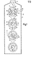
- Fig. 1 eine Vorrichtung mit vier übereinander angeordneten Trocknungseinheiten mit Rotor, Warmlufteinlaßrohr und umgebendem Mantelrohr in einem Gehäuse,
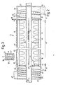
- Fig. 2 einen Schnitt durch eine Einheit nach Fig. 1,
- Fig. 3 einen Ausschnitt aus einer Draufsicht auf ein Mantelrohr zur Darstellung des den Mantelrohrauslaß abdeckenden Gitters,
- Fig. 4 eine abgewandelte Vorrichtung mit auf dem Trocknungslufteinlaßrohr angeordneter Paddelschnecke.
- In einem in Fig. 1 dargestellten wärmeisolierenden Gehäuse 3 sind übereinander vier Trocknungseinheiten 5 angeordnet. Das Gehäuse 3 besteht aus Kunststoffplatten und ist damit gut wärmeisolierend ausgebildet. Gleichzeitig dient das Gehäuse 3 auch der Luftführung. Die Trocknungseinheiten 5 setzen sich aus mehren Teilen zusammen. Außen umgeben werden die Trocknungseinheiten 5 jeweils von einem Mantelrohr 7, das mit einem sich längs seiner Oberseite 9 erstreckenden, perforierten Auslaß 11 versehen ist. Innerhalb des Mantelrohres 7 dreht sich ein Paddelrotor 13. Dieser Paddelrotor 13 besteht beispielsweise aus Stahlband-Rotorkränzen 15, die über Längsstreben 16 untereinander verbunden sind, und Lagerringen 17. An den Längsstreben 16 sind Paddel 19 zum Längsfördern der Schnitzel und Abstreifer 20 zum Abstreifen von Staub und Schnitzeln vom perforierten Auslaß 11 angeordnet. Die Paddel 19 weisen von den Längsstreben 16 zur Rohrmitte nach innen. Die Abstreifer 20, die an den Längsstreben 16 angeordnet sind erstrecken sich bis dicht (ca. 2 mm) vor das M ntelrohr 7 nach außen. Die Lagerringe 17 stützen sich an einem Trocknungslufteinlaßrohr 21 ab, durch das Trocknungsluft in das Innere der Trocknungseinheit 5 eingeleitet wird. Das sich beim Betrieb entgegengesetzt zum Paddelrotor 13 drehende Trocknungslufteinlaßrohr 21 ist mit sich längs einer Längslinie 29 erstreckenden Schlitzen 23 versehen, aus denen die Trocknungsluft (beispielsweise etwa 50.000 bis 100.000 m3/h und Trocknungseinheit in das Mantelrohr 7 hineingedrückt wird. Die Schlitze sind in voller Länge mit einem hitzebeständigen, zugfesten Gitter 24 abgedeckt, das in Fig. 2 - 4 näher dargestellt und beschrieben ist.
- Alle vier Trocknungseinheiten haben den gleichen Aufbau und die gleiche Funktionsweise. Sie fördern nur jeweils in entgegengesetzten Richtungen, um damit eine zweckmässige hin- und hergehende Bearbeitung zuzulassen.
- Einzelheiten einer erfindungsgemäß ausgebildeten Trocknungseinheit sind aus Fig. 2 bis 4 zu erkennen. Das Mantelrohr 7 ist an seinen Kopfenden 25 mittels Deckeln 27 verschlossen (Fig. 2 und 4) Die Deckel 27 dienen zugleich der Lagerung des Trocknungslufteinlaßrohres 21. Lagerung und Antrieb des Trocknungslufteinlaßrohres 21 sind in Einzelheiten nicht näher erläutert. Der Konstrukteur bedient sich dabei üblicher gebräuchlicher Konstruktionen. Das gleiche gilt für den Paddelrotor 13, der beispielsweise über einen nach außen geführten Zahnkranz 28 von einem nicht näher erläuterten Antrieb drehbar ist.
- Durch die Längsschlitze 23 im Trocknungslufteinlaßrohr 21 kann in Richtung eines Pfeiles 33 zugeführte warme oder heiße Trocknungsluft radial in den vom Mantelrohr 7 umschlossenen Trocknungsraum 41 eingeblasen werden. Aus Fig. 1 ist anhand von Pfeilen 35 erkennbar, wie die Trocknungsluft das Trocknungslufteinlaßrohr 21 radial verläßt und dabei durch den Paddelrotor 13 von innen nach außen hindurchbläst. Da das Schnitzelmaterial in dem Mantelrohr 7 mittels der Paddel in axiale Bewegung kommt, bekommen die Luftstrahlen eine zusätzliche axiale Komponente. Die Verweilzeit der Heißluft im Material kann sich dadurch verlängern.
- In dem Trocknungsraum 41 zwischen de.m Mantelrohr 7 und dem Trocknungslufteinlaßrohr 21 fördern die Paddel 19 die das Trocknungslufteinlaßrohr 21 umgebenden Schnitzel 44 bei der Trocknungseinheit nach Fig. 2 in Richtung eines Pfeiles 45 längs der Trocknungseinheit. Zusätzlich verleihen die Paddel 19 den Schnitzeln noch eine turbulente Bewegung entsprechend ihrer Gradeinstellung zur Förderrichtung und Umlaufgeschwindigkeit.
- Am Trocknungslufteinlaßrohr 21 sind im Bereich A nahe dem Materialeinlaß 47 mehrere Gänge einer bis auf ca. 3 mm an das Mantelrohr 7 herangeführten Schnecke 49 fest angeordnet, die die Schnitzel in den Trocknungsraum 41 (Bereich B) in Richtung des Pfeiles 45 hineindrücken und zugleich den Trocknungsraum 41 gegenüber dem Einlaß 47 unter Zuhilfenahme der Schnitzel abdichten. Im Auslaßbereich C sind am Trocknungslufteinlaßrohr 21 Schneckengänge 53 vorgesehen. Zwischen diesen Schneckengängen 53 ist ein Schneckenblatt weggelassen, wodurch sich ein Materialpfropfen ausbildet, der das Ausströmen der Trocknungsluft aus dem Trocknungsraum 41 zum Auslaß 55 verhindert.
- An der Oberseite 9 des Mantelrohres 7 ist in Fig. 2 der Auslaß 11 aus dem Mantelrohr erkennbar. Dieser Mantelrohrauslaß 11 besteht aus einer breiten schlitzförmigen Öffnung. über den Mantelrohrauslaß 11 ist ein Gitter 57 gespannt.Dieses Gitter 57 besteht vorzugsweise aus einem mit Teflon beschichteten Fiberglasgittergeflecht. Auch andere Gittermaterialien sind denkbar. Das Gitter 57 ist längs der Auslaßöffnungsränder auf der Oberseite 9 des Mantelrohres 7 beispielsweise mit Haltestreifen 59 festgelegt. Das Gittergeflecht hat beispielsweise eine Maschenweite von ca. 4 mm und weist 70 % offene Fläche auf. Es ist hitzebeständig und zugfest.
- In Fig. 3 ist eine Draufsicht III auf einen Ausschnitt des Mantelrohres 7 nach Fig. 2 und 4 abgebildet. Der Auslaß 11 wird dabei deutlich sichtbar von dem Gitter 57 überdeckt, wobei sich zwischen den Maschen des Gitters 57 Durchblasöffnungen 61 ausbilden. Es hat sich gezeigt, daß hochfliegende Schnitzel und Staub die Durchblasöffnungen nicht verstopfen, wenn beispielsweise vier Abstreifer 20 die aus Schnitzeln und Staubteilen bestehende, sich am Gitter ablagernde Schicht ständig abstreifen und die Ablagerungsreste auf gleicher Dicke von ca. 6 mm halten. Dies führt zu einem nahezu staubfreien Luftaustritt ohne Druckschwankungen.
- Wenn die einzelnen Trocknungseinheiten, wie zu Fig. 1 bereits erläutert, in wechselnder Richtung fördern, dann werden die Schnitzel jeweils in eine Trocknungseinheit, beispielsweise in die oberste Trocknungseinheit 5 nach Fig. 2 von oben hineingeschüttet; sie durchwandern turbulent durchgewirbelt diese oberste Trocknungseinheit in Richtung des Pfeiles 45 und verlassen sie durch den Auslaß 55. Die Schnitzel fallen dann in den Einlaß der in Gegenrichtung fördernden, darunterliegenden Trocknungseinheit. Damit wird ein kontinuierlicher Förderbetrieb in wechselnder Richtung durchgeführt.
- Das Mantelrohr 7 der zweituntersten Trocknungseinheit wird von der Warmluft umspült, die aus dem Mantelrohr 7 der untersten Trocknungseinheit ausströmt. Alle ausgeblasene Warmluft strömt in Richtung der Pfeile 69 nach oben und umspült alle höher gelegenen Trocknungseinheiten 5. Damit werden alle höher gelegenen Mantelrohre 7 von außen mit aufgeheizt, und die Wärme kann aus dem Inneren dieser Trocknungseinheiten nicht entweichen. Die Warmluft wird damit auf engem Raum und insbesondere in den Trocknungseinheiten konzentriert.und die eingebrachte Wärme bleibt, abgesehen von der durch den Abluftkanal 71 entweichenden Wärme, innerhalb der Vorrichtung festgehalten. Zum Betrieb der Anlage wird nur die zusätzl. Energie benötigt, die zum Drehen der Trocknungslufteinlaßrohre 21 und der Paddelrotoren 13 benötigt wird. Wie aus dem Schemabild der obersten Einheit nach Fig. 1 zu erkennen ist, drehen sich das Einlaßrohr 21 und der Rotor 13 in entgegengesetzten Richtungen.Die gegensätzlichen Richtungen sind durch die Pfeile 73 für das Trocknungslufteinlaßrohr 21 und 75 für den Paddelrotor angedeutet.
- Fig. 4 zeigt eine Abwandlung der Trocknungseinheit 5 nach Fig. 2. Die Trocknungseinheit 105 nach Fig. 4 entspricht in weiten Teilen der nach Fig. 2 und 3. Gleiche Teile sind der Übersichtlichkeit wegen mit gleichen Bezugszeichen versehen. Im stillstehenden Mantelrohr 7 dreht sich das Trocknungslufteinlaßrohr 121. Im Bereich A des Mantelrohreinlasses 47 sind auf dem Trocknungslufteinlaßrohr 121 wieder mehrere Schneckengänge 49 zum Einführen der Schnitzel in den Trocknungsraum 41 (Bereich B) und Abdichten gegenüber diesem befestigt. Im Bereich C des Materialauslasses 55 ist wie in der Ausführungsform nach Fig. 2 ein Schneckengang weggelassen, wodurch sich zur zusätzlichen Abdichtung ein Materialpfropfen bildet.
- Abweichend von Fig. 2 ist der Fördermechanismus. An die Stelle des Paddelrotors13 tritt eine Paddelschnecke. Dazu sind auf dem Trocknungslufteinlaßrohr 121 Schneckenpaddel 119 angeordnet. Diese Schneckenpaddel 119 reichen vom Einlaßrohr 121 nach außen bis kurz vor die Innenwand des Mantelrohres 7 bzw. bis ca. 6 mm vor das Gittergeflecht, um so auch die Gitteröffnungen61 durch Abstreifen mittels der Schneckenpaddel 119 freizuschieben. Das sich drehende Trocknungslufteinlaßrohr 121 sorgt mit seinen sich mitdrehenden Schneckenpaddeln für die Materialförderung in Richtung des Pfeiles 45 und je nach ihrer Gradeinstellung zur Förderrichtung und Umlaufgeschwindigkeit zusätzlich für eine turbulente Verwirbelung der Schnitzel.
- Bei beiden Ausbildungsarten der Trocknungseinheit wird der Materialstrom mittels der Paddel axial fortbewegt und turbulent verwirbelt. Die Trocknungsluft bläst durch die Einlaßschlitze 23 radial in den Trocknungsraum 41 ein, und zwar mit umlaufendem Blasstrahl. Die Paddel halten die Schnitzel turbulent in der Schwebe. Auf diese Weise ist ein allseitiger Luftkontakt der Schnitzel gegeben. Die Kontaktzeit zwischen der Trocknungsluft und den Schnitzeln beträgt ca. 2 sec.
- Die Paddel sind vorzugsweise längs einer oder mehrerer Mantellinien angeordnet, die über die Länge des Trocknungsraumes 41 (Bereich B) das Mantelrohr 7 einmal schraubenlinienförmig umschlingen.
Claims (15)
unmittelbar auf dem Trocknungslufteinlaßrohr (121) Schneckenpaddel (119) angeordnet sind, die sich mit dem Einlaßrohr (121) drehen und die Schnitzel längs des Trocknungsraumes (41) zwischen dem stillstehenden Mantelrohr (7) und dem Trocknungslufteinlaßrohr (121) axial fördern.
Priority Applications (3)
| Application Number | Priority Date | Filing Date | Title |
|---|---|---|---|
| AT83100268T ATE33070T1 (de) | 1982-01-22 | 1983-01-14 | Verfahren zum trocknen von zuckerruebenschnitzeln und vorrichtung zur durchfuehrung dieses verfahrens. |
| PCT/DE1984/000007 WO1984002768A1 (fr) | 1983-01-14 | 1984-01-16 | Procede de sechage complet de cossettes de betteraves sucrieres et installation pour executer le procede |
| JP59500611A JPS60500459A (ja) | 1983-01-14 | 1984-01-16 | 砂糖大根チツプの完全乾燥法及びこの方法を実施する装置 |
Applications Claiming Priority (2)
| Application Number | Priority Date | Filing Date | Title |
|---|---|---|---|
| DE19823201843 DE3201843A1 (de) | 1982-01-22 | 1982-01-22 | "verfahren und vorrichtung zum trocknen von zuckerruebenschnitzeln" |
| DE3201843 | 1982-01-22 |
Publications (3)
| Publication Number | Publication Date |
|---|---|
| EP0084820A2 true EP0084820A2 (de) | 1983-08-03 |
| EP0084820A3 EP0084820A3 (en) | 1984-09-05 |
| EP0084820B1 EP0084820B1 (de) | 1988-03-16 |
Family
ID=6153594
Family Applications (1)
| Application Number | Title | Priority Date | Filing Date |
|---|---|---|---|
| EP83100268A Expired EP0084820B1 (de) | 1982-01-22 | 1983-01-14 | Verfahren zum Trocknen von Zuckerrübenschnitzeln und Vorrichtung zur Durchführung dieses Verfahrens |
Country Status (3)
| Country | Link |
|---|---|
| EP (1) | EP0084820B1 (de) |
| AT (1) | ATE33070T1 (de) |
| DE (2) | DE3201843A1 (de) |
Cited By (1)
| Publication number | Priority date | Publication date | Assignee | Title |
|---|---|---|---|---|
| CN110030809A (zh) * | 2019-04-17 | 2019-07-19 | 焦作大学 | 一种植物茎部切片干燥装置 |
Families Citing this family (1)
| Publication number | Priority date | Publication date | Assignee | Title |
|---|---|---|---|---|
| CN109916165A (zh) * | 2019-03-01 | 2019-06-21 | 广州市盈夏机械技术有限公司 | 一种节能环保多功能双立罐滚筒烘干机 |
Family Cites Families (6)
| Publication number | Priority date | Publication date | Assignee | Title |
|---|---|---|---|---|
| DE165644C (de) * | ||||
| DE35176C (de) * | 1885-08-15 | 1886-04-05 | E. BACH in Leipzig, Alexanderstr. 38, Hof II | Trockenapparat |
| US1416960A (en) * | 1921-08-15 | 1922-05-23 | Ladisch Karl | Drier |
| US2019668A (en) * | 1933-07-03 | 1935-11-05 | Jesse J Fowler | Drier |
| US3494049A (en) * | 1968-03-18 | 1970-02-10 | Universal Oil Prod Co | Apparatus for fluid treatment of granular material |
| DE2143462B2 (de) * | 1971-08-31 | 1973-09-27 | Karl 6080 Gross-Gerau Kron | Gerät zur kontinuierlichen Trocknung landwirtschaftlicher Erzeugnisse |
-
1982
- 1982-01-22 DE DE19823201843 patent/DE3201843A1/de not_active Ceased
-
1983
- 1983-01-14 AT AT83100268T patent/ATE33070T1/de not_active IP Right Cessation
- 1983-01-14 DE DE8383100268T patent/DE3376031D1/de not_active Expired
- 1983-01-14 EP EP83100268A patent/EP0084820B1/de not_active Expired
Cited By (1)
| Publication number | Priority date | Publication date | Assignee | Title |
|---|---|---|---|---|
| CN110030809A (zh) * | 2019-04-17 | 2019-07-19 | 焦作大学 | 一种植物茎部切片干燥装置 |
Also Published As
| Publication number | Publication date |
|---|---|
| ATE33070T1 (de) | 1988-04-15 |
| EP0084820A3 (en) | 1984-09-05 |
| EP0084820B1 (de) | 1988-03-16 |
| DE3376031D1 (en) | 1988-04-21 |
| DE3201843A1 (de) | 1983-08-04 |
Similar Documents
| Publication | Publication Date | Title |
|---|---|---|
| DE3142985C2 (de) | ||
| DE3248384A1 (de) | Einrichtung zur trocknung von feststoffen | |
| DE2741710A1 (de) | Verfahren und vorrichtung zum trennen von feststoffen und fluessigkeiten aus einer suspension | |
| DE3518323A1 (de) | Verfahren und vorrichtung zum trocknen von klaerschlamm | |
| DE2649633A1 (de) | Verfahren und vorrichtung zum behandeln von fein verteiltem schuettgut mit gas ohne ueberdruck | |
| DE2635079A1 (de) | Getreidetrockner | |
| DE212018000309U1 (de) | Förderschnecke für Vorrichtung zur Entsorgung von Nahrungsmittelabfällen | |
| DE2820454B2 (de) | Anlage zur Kühlung und Trennung von Abgüssen und Formsand | |
| WO2010046195A2 (de) | Extraktive tabakmaterial-extrusion | |
| EP1147805B1 (de) | Verfahren zur Dispergierung eines Papierfaserstoffes sowie Anlage zur Durchführung des Verfahrens | |
| DE2611853A1 (de) | Verfahren zum trocknen landwirtschaftlicher futtermittel und schlammartiger materialien | |
| DE2241264A1 (de) | Trockentrommel | |
| DE2248051A1 (de) | Verfahren zum kontinuierlichen trocknen von tropfnassen, koernigen und/oder stueckigen guetern und vorrichtung zur durchfuehrung des verfahrens | |
| DE1411283A1 (de) | Siebanordnung in zylindrischen Behaeltern fuer Zellstoffbrei | |
| DE202023105516U1 (de) | Kohleblöckezerkleinerungsvorrichtung für thermisches Kraftwerk | |
| DE2301464A1 (de) | Verfahren und vorrichtung zum einstellen von betriebsparametern eines durch eine leitung fliessenden fluids | |
| EP0084820A2 (de) | Verfahren zum Trocknen von Zuckerrübenschnitzeln und Vorrichtung zur Durchführung dieses Verfahrens | |
| DE4121223A1 (de) | Verfahren zur aufbereitung von schlaemmen unterschiedlicher konsistenz und anlage zur durchfuehrung des verfahrens | |
| EP0611937A1 (de) | Mischer-Trockner | |
| DE2111380B2 (de) | Vorrichtung zum pilieren von seifen oder aehnlichen, pastenartigen massen | |
| WO1984002768A1 (fr) | Procede de sechage complet de cossettes de betteraves sucrieres et installation pour executer le procede | |
| EP2437016B1 (de) | Trocknertrommel für hausmüll und verfahren zum trocknen von hausmüll | |
| DE2745179A1 (de) | Verfahren und vorrichtung zum chargenweisen mischen, trocknen und/oder granulieren von schuettguetern | |
| DE1461012B2 (de) | Vorrichtung zum zerfasern von papierstoff | |
| DE19542301B4 (de) | Verfahren und Einrichtung zum Trocknen von schlammartigem Trockengut, insbesondere Klärschlamm |
Legal Events
| Date | Code | Title | Description |
|---|---|---|---|
| PUAI | Public reference made under article 153(3) epc to a published international application that has entered the european phase |
Free format text: ORIGINAL CODE: 0009012 |
|
| AK | Designated contracting states |
Designated state(s): AT BE CH DE FR GB IT LI LU NL SE |
|
| RAP1 | Party data changed (applicant data changed or rights of an application transferred) |
Owner name: KAMMER, UTE |
|
| PUAL | Search report despatched |
Free format text: ORIGINAL CODE: 0009013 |
|
| AK | Designated contracting states |
Designated state(s): AT BE CH DE FR GB IT LI LU NL SE |
|
| 17P | Request for examination filed |
Effective date: 19850302 |
|
| 17Q | First examination report despatched |
Effective date: 19870630 |
|
| GRAA | (expected) grant |
Free format text: ORIGINAL CODE: 0009210 |
|
| AK | Designated contracting states |
Kind code of ref document: B1 Designated state(s): AT BE CH DE FR GB IT LI LU NL SE |
|
| REF | Corresponds to: |
Ref document number: 33070 Country of ref document: AT Date of ref document: 19880415 Kind code of ref document: T |
|
| REF | Corresponds to: |
Ref document number: 3376031 Country of ref document: DE Date of ref document: 19880421 |
|
| GBT | Gb: translation of ep patent filed (gb section 77(6)(a)/1977) | ||
| ITF | It: translation for a ep patent filed | ||
| ET | Fr: translation filed | ||
| PLBE | No opposition filed within time limit |
Free format text: ORIGINAL CODE: 0009261 |
|
| STAA | Information on the status of an ep patent application or granted ep patent |
Free format text: STATUS: NO OPPOSITION FILED WITHIN TIME LIMIT |
|
| PGFP | Annual fee paid to national office [announced via postgrant information from national office to epo] |
Ref country code: FR Payment date: 19890127 Year of fee payment: 7 |
|
| PGFP | Annual fee paid to national office [announced via postgrant information from national office to epo] |
Ref country code: DE Payment date: 19890130 Year of fee payment: 7 Ref country code: CH Payment date: 19890130 Year of fee payment: 7 |
|
| ITTA | It: last paid annual fee | ||
| PG25 | Lapsed in a contracting state [announced via postgrant information from national office to epo] |
Ref country code: LU Free format text: LAPSE BECAUSE OF NON-PAYMENT OF DUE FEES Effective date: 19890131 |
|
| PGFP | Annual fee paid to national office [announced via postgrant information from national office to epo] |
Ref country code: SE Payment date: 19890131 Year of fee payment: 7 Ref country code: NL Payment date: 19890131 Year of fee payment: 11 Ref country code: LU Payment date: 19890131 Year of fee payment: 7 Ref country code: AT Payment date: 19890131 Year of fee payment: 7 |
|
| PGFP | Annual fee paid to national office [announced via postgrant information from national office to epo] |
Ref country code: GB Payment date: 19890228 Year of fee payment: 7 |
|
| 26N | No opposition filed | ||
| PGFP | Annual fee paid to national office [announced via postgrant information from national office to epo] |
Ref country code: BE Payment date: 19890308 Year of fee payment: 7 |
|
| PG25 | Lapsed in a contracting state [announced via postgrant information from national office to epo] |
Ref country code: GB Effective date: 19900114 Ref country code: AT Effective date: 19900114 |
|
| PG25 | Lapsed in a contracting state [announced via postgrant information from national office to epo] |
Ref country code: SE Effective date: 19900115 |
|
| PG25 | Lapsed in a contracting state [announced via postgrant information from national office to epo] |
Ref country code: LI Effective date: 19900131 Ref country code: CH Effective date: 19900131 Ref country code: BE Effective date: 19900131 |
|
| BERE | Be: lapsed |
Owner name: KAMMER UTE Effective date: 19900131 |
|
| PG25 | Lapsed in a contracting state [announced via postgrant information from national office to epo] |
Ref country code: NL Effective date: 19900801 |
|
| GBPC | Gb: european patent ceased through non-payment of renewal fee | ||
| NLV4 | Nl: lapsed or anulled due to non-payment of the annual fee | ||
| PG25 | Lapsed in a contracting state [announced via postgrant information from national office to epo] |
Ref country code: FR Effective date: 19900928 |
|
| REG | Reference to a national code |
Ref country code: CH Ref legal event code: PL |
|
| PG25 | Lapsed in a contracting state [announced via postgrant information from national office to epo] |
Ref country code: DE Effective date: 19901002 |
|
| REG | Reference to a national code |
Ref country code: FR Ref legal event code: ST |
|
| EUG | Se: european patent has lapsed |
Ref document number: 83100268.8 Effective date: 19901106 |