EP0084823A1 - Dispositif de transfert de conteneurs - Google Patents
Dispositif de transfert de conteneurs Download PDFInfo
- Publication number
- EP0084823A1 EP0084823A1 EP83100284A EP83100284A EP0084823A1 EP 0084823 A1 EP0084823 A1 EP 0084823A1 EP 83100284 A EP83100284 A EP 83100284A EP 83100284 A EP83100284 A EP 83100284A EP 0084823 A1 EP0084823 A1 EP 0084823A1
- Authority
- EP
- European Patent Office
- Prior art keywords
- container
- containers
- transfer device
- rollers
- load
- Prior art date
- Legal status (The legal status is an assumption and is not a legal conclusion. Google has not performed a legal analysis and makes no representation as to the accuracy of the status listed.)
- Withdrawn
Links
- 238000005096 rolling process Methods 0.000 claims abstract description 6
- 239000000725 suspension Substances 0.000 claims description 8
- 230000008878 coupling Effects 0.000 claims 1
- 238000010168 coupling process Methods 0.000 claims 1
- 238000005859 coupling reaction Methods 0.000 claims 1
- 238000000034 method Methods 0.000 description 5
- 230000003137 locomotive effect Effects 0.000 description 3
- 238000006243 chemical reaction Methods 0.000 description 1
- 238000006073 displacement reaction Methods 0.000 description 1
- 238000005516 engineering process Methods 0.000 description 1
- 230000010354 integration Effects 0.000 description 1
- 230000003993 interaction Effects 0.000 description 1
Images

Classifications
-
- B—PERFORMING OPERATIONS; TRANSPORTING
- B61—RAILWAYS
- B61F—RAIL VEHICLE SUSPENSIONS, e.g. UNDERFRAMES, BOGIES OR ARRANGEMENTS OF WHEEL AXLES; RAIL VEHICLES FOR USE ON TRACKS OF DIFFERENT WIDTH; PREVENTING DERAILING OF RAIL VEHICLES; WHEEL GUARDS, OBSTRUCTION REMOVERS OR THE LIKE FOR RAIL VEHICLES
- B61F1/00—Underframes
- B61F1/06—Underframes specially adapted for locomotives or motor-driven railcars
-
- B—PERFORMING OPERATIONS; TRANSPORTING
- B61—RAILWAYS
- B61D—BODY DETAILS OR KINDS OF RAILWAY VEHICLES
- B61D3/00—Wagons or vans
- B61D3/16—Wagons or vans adapted for carrying special loads
- B61D3/20—Wagons or vans adapted for carrying special loads for forwarding containers
-
- B—PERFORMING OPERATIONS; TRANSPORTING
- B61—RAILWAYS
- B61D—BODY DETAILS OR KINDS OF RAILWAY VEHICLES
- B61D47/00—Loading or unloading devices combined with vehicles, e.g. loading platforms, doors convertible into loading and unloading ramps
-
- B—PERFORMING OPERATIONS; TRANSPORTING
- B66—HOISTING; LIFTING; HAULING
- B66C—CRANES; LOAD-ENGAGING ELEMENTS OR DEVICES FOR CRANES, CAPSTANS, WINCHES, OR TACKLES
- B66C23/00—Cranes comprising essentially a beam, boom, or triangular structure acting as a cantilever and mounted for translatory of swinging movements in vertical or horizontal planes or a combination of such movements, e.g. jib-cranes, derricks, tower cranes
- B66C23/54—Cranes comprising essentially a beam, boom, or triangular structure acting as a cantilever and mounted for translatory of swinging movements in vertical or horizontal planes or a combination of such movements, e.g. jib-cranes, derricks, tower cranes with pneumatic or hydraulic motors, e.g. for actuating jib-cranes on tractors
Definitions
- the invention relates to a device for moving containers, such as containers, swap bodies or the like on side storage surfaces, preferably for arrangement on railway vehicles, for moving below the overhead line for electric traction vehicles by means of two swing-out and liftable booms that are at a greater distance than the length the containers to be moved are arranged and each carry at least one pendulum-suspended rolling element in the front area, which is arranged in a guide of the load receiver in the form of a spreader.
- a handling system for containers and pallets with supply ramps has become known, to which loading and unloading devices for road vehicles and tracks for container trains are assigned, and which roller conveyors for computer-controlled movements of the containers.
- the ramps provided with cross-conveying roller units have in their longitudinal center level longitudinal conveying systems with cross-conveying roller units, the rollers of the roller units as well as the rollers of cross-conveying roller units arranged on the wagons being adapted in shape to the grooves on the container or plate underside and according to one Module are arranged.
- a device which consists of a frame arranged above the vehicle platform, which can be moved in height by means of a hydraulic working cylinder.
- This frame running in the longitudinal direction of the vehicle platform has in its end regions a telescopically movable crosswise to the longitudinal direction of the platform carriage Booms that each have a loading frame at their free ends for hanging the containers.
- Each loading frame is attached to the telescopic movable boom so that the loading frame is attached at one end to the free end of the outer extendable boom frame, while the rear end of the loading frame is guided on the boom so that the loading frame extends from the outer one when the boom is extended Boom arm is carried while the rear end of the loading frame is held and guided on the boom.
- the vehicle having this transfer device is provided with floor supports which permit vertical support with the result that long cantilevers cannot be used for reasons of vehicle stability.
- the height of the booms with the loading frames allows several containers to be stacked on top of one another (GB-PS 1 277 001).
- Another known reloading device for railway vehicles consists of a crane bridge which can be moved in the transverse direction of the vehicle on guide rails and which has booms that can be extended and retracted on both sides, namely transversely to the longitudinal direction of the vehicle, and which carry trolleys and lifting elements in a compact design.
- the crane bridge provided is arranged transversely to the longitudinal direction of the vehicle and can be moved parallel to the longitudinal direction of the vehicle, while the booms can be moved in and out transversely to the longitudinal direction of the vehicle (DE-PS 827 321).
- a further known transfer device namely in the form of a lifting and sliding mechanism for covered railway carriages, one is below the roof of a railway vehicle and transversely to its longitudinal direction arranged crane bridge-like support frame is provided with a retractable and extendable cantilever arm, over the free end of which an elevator rope is arranged for the load to be reloaded.
- the supporting frame can be moved in the vehicle longitudinal direction by means of guide rails which run in the vehicle longitudinal direction (DE-PS 434 212).
- the device consists of two vertical, portal-shaped support frames arranged on a vehicle platform, which support crossways of the vehicle for a crane bridge with a loading frame.
- the two height-adjustable support frames have cantilevers that can be swiveled on one or both sides about vertical axes with the lanes adjoining the carriageways in the swung-out position for extending the crane bridge from the side.
- Length-adjustable supports are provided on the side, which are swung out with the cantilevers and are supported on surfaces arranged parallel to the rails (DE-OS 2 834 163).
- Another known handling device is designed such that the cargo is transferred by means of a rotating boom.
- the jib tips are mounted in guides for the load handler.
- This type of design offers no security against displacement of the cargo unit, such as handling in the inclined track (DE-OS 1 531 062).
- the object of the invention is to provide a simple device of the generic type, in addition to the implementation under electrical contact wires of railways also for use on vehicles with the specified vehicle boundary profile to ensure mobility and a versatile loading and unloading without shifting relative to the handling device on or from different parking spaces and vehicles.
- the rolling elements are connected either by ring-like coupled pulling elements, such as ropes or chains, which are deflected by rollers arranged on the load receiver, or by toothed racks, which are in engagement with a gearwheel fastened in the middle of the load receiver , are connected. This reliably prevents the cargo unit from shifting relative to the transhipment device due to external influences (e.g. transshipment in the inclined track).
- the deflecting rollers or the gearwheel on the load suspension be arranged so as to be displaceable in the direction of the guides.
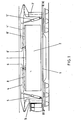
- pillars 3,3 ' there are two pillars 3,3 'arranged on a platform 1 at a greater distance than the container 2 to be moved.
- These columns 3, 3 ' are rotatably supported about a vertical axis and are rotated by means of a motor and slewing ring, not shown.
- the columns 3, 3 'carry cantilevers 4, 4' which can be pivoted about an axis arranged perpendicular to the axis of the column.
- the pivoting movement of the boom 4,4 ' is effected by hydraulic cylinders 5,5', which are arranged between the rotatable column and the boom.
- a roller body in the form of a roller carriage 6, 6 ' is located at the tip of the arms 4, 4.
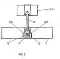
- the roller carriage 6, 6 ' consists of a frame 11 which has two rollers 12 on each of the two longitudinal sides.
- the roller carriage 6,6 can of course also be provided with lateral guide rollers.
- the connection between the frame 11 and the arm 4, 4 ' is established by means of a pull rod 13, which is gimbaled on the arm 4, 4' and on the frame 11 about an axis arranged parallel to the rollers 12.
- rollers 12 of the roller carriages 6, 6 ' are supported vertically in roller tracks 8, 8' of a load suspension.
- the roller carriages 6, 6 ' are connected by means of a rope 21 via deflection rollers 22, 22'.
- the deflection rollers 22, 22 ' are arranged at the ends of the load receiver 7 in the direction of the guides 8, 8'. Hydraulic cylinders, for example, are not used for this purpose.
- the known load receiver 7 consists of a frame with locking elements for holding the 10 ", 20", 30 ", 40" container 2 or of several containers 2 and four gripping arms arranged on the frame for receiving swap bodies.
- the container 2 to be transferred stands on a storage area next to the transfer device. From the rest position, the arms 4, 4 'and thus the load suspension 7 are raised by means of the hydraulic cylinders 5, 5' to such an extent that the load suspension 7 reaches its working position. By turning the columns 3, 3 ', the load receiver 7 is moved over the container 2. The roller carriages 6,6 'move outwards in their roller conveyors 8,8'. Different angles of rotation of the columns 3, 3 ' also compensate for larger deviations in the parallelism between the container and the transfer device.
- the load receiver 7 By shifting the deflection rollers 22, 22 'in the same direction, the load receiver 7 is displaced in the longitudinal direction in such a way that the container 2 can be held properly.
- the load receiver 7 By placing the cantilevers 4, 4 ', the load receiver 7 is placed on the container 2 and locked with it.
- the container 2 By lifting the arms 4, 4 'and rotating the columns 3, 3' beyond the center of the transfer device, the container 2 can be placed on the opposite side.
Landscapes
- Engineering & Computer Science (AREA)
- Mechanical Engineering (AREA)
- Transportation (AREA)
- Loading Or Unloading Of Vehicles (AREA)
- Warehouses Or Storage Devices (AREA)
Applications Claiming Priority (2)
| Application Number | Priority Date | Filing Date | Title |
|---|---|---|---|
| DE19823201041 DE3201041C2 (de) | 1982-01-15 | 1982-01-15 | "Einrichtung zum Umsetzen von Behältern" |
| DE3201041 | 1982-01-15 |
Publications (1)
| Publication Number | Publication Date |
|---|---|
| EP0084823A1 true EP0084823A1 (fr) | 1983-08-03 |
Family
ID=6153115
Family Applications (1)
| Application Number | Title | Priority Date | Filing Date |
|---|---|---|---|
| EP83100284A Withdrawn EP0084823A1 (fr) | 1982-01-15 | 1983-01-14 | Dispositif de transfert de conteneurs |
Country Status (2)
| Country | Link |
|---|---|
| EP (1) | EP0084823A1 (fr) |
| DE (1) | DE3201041C2 (fr) |
Cited By (4)
| Publication number | Priority date | Publication date | Assignee | Title |
|---|---|---|---|---|
| WO1996017797A1 (fr) * | 1994-12-07 | 1996-06-13 | Elin Energieversorgung Gmbh | Systeme de transbordement ferroviaire et procede de transbordement de conteneurs de transport |
| FR2992277A1 (fr) * | 2012-06-26 | 2013-12-27 | Juha Seitsonen | Dispositif pour la manutention de conteneurs sous catenaires ferroviaires |
| WO2015136324A1 (fr) * | 2014-03-11 | 2015-09-17 | Élő Mini-Világ Környezetvédelmi Alapítvány / Living Mini-World Environmental Foundation | Nouveau système de rail sur grue rapide autonome |
| WO2021046454A1 (fr) * | 2019-09-05 | 2021-03-11 | Schneider Daniel J | Système de transport intermodal amélioré |
Families Citing this family (1)
| Publication number | Priority date | Publication date | Assignee | Title |
|---|---|---|---|---|
| DE4402905C2 (de) * | 1994-01-31 | 1997-02-06 | Mannesmann Ag | Kran, insbesondere gleisgebundener Mobilkran |
Citations (7)
| Publication number | Priority date | Publication date | Assignee | Title |
|---|---|---|---|---|
| FR1463440A (fr) * | 1966-01-11 | 1966-12-23 | Appareil de manutention mécanique | |
| DE1531062A1 (de) * | 1967-06-08 | 1969-10-30 | Steinbock Gmbh | Verlade- und Foerderzeug fuer Container |
| DE1946369A1 (de) * | 1968-09-23 | 1970-04-23 | Schwermaschb S M Kirow Veb | Ortsveraenderlicher Container-Kran |
| GB1201038A (en) * | 1966-10-22 | 1970-08-05 | Coast Lines Ltd | Improvements in and relating to a spreader frame for a lifting device |
| FR96600E (fr) * | 1968-12-30 | 1973-01-29 | Mariage Georges | Perfectionnement aux appareils élévateurs transbordeurs pour chargement latéral sur véhicules routiers des containers et autres charges. |
| GB2015970A (en) * | 1978-02-27 | 1979-09-19 | Stothert & Pitt Ltd | Combined transportation and transfer means for freight containers or the like |
| DE2834163A1 (de) * | 1978-08-04 | 1980-02-21 | Foerdertechnische Forschungsge | Eisenbahnfahrzeug zum umsetzen von behaeltern wie containern auf seitlich des fahrzeuges befindlichen abstellflaechen |
Family Cites Families (3)
| Publication number | Priority date | Publication date | Assignee | Title |
|---|---|---|---|---|
| FR1588202A (fr) * | 1968-04-30 | 1970-04-10 | ||
| DE6929642U (de) * | 1969-07-21 | 1970-04-23 | Dornier System Gmbh | Vorrichtung zum aufnehmen und bewegen von teilen |
| DE2742461C2 (de) * | 1977-09-21 | 1983-03-17 | Fördertechnische Forschungsgesellschaft mbH, 2000 Hamburg | Eisenbahnfahrzeug zum Umsetzen von Behältern, wie Containern |
-
1982
- 1982-01-15 DE DE19823201041 patent/DE3201041C2/de not_active Expired
-
1983
- 1983-01-14 EP EP83100284A patent/EP0084823A1/fr not_active Withdrawn
Patent Citations (7)
| Publication number | Priority date | Publication date | Assignee | Title |
|---|---|---|---|---|
| FR1463440A (fr) * | 1966-01-11 | 1966-12-23 | Appareil de manutention mécanique | |
| GB1201038A (en) * | 1966-10-22 | 1970-08-05 | Coast Lines Ltd | Improvements in and relating to a spreader frame for a lifting device |
| DE1531062A1 (de) * | 1967-06-08 | 1969-10-30 | Steinbock Gmbh | Verlade- und Foerderzeug fuer Container |
| DE1946369A1 (de) * | 1968-09-23 | 1970-04-23 | Schwermaschb S M Kirow Veb | Ortsveraenderlicher Container-Kran |
| FR96600E (fr) * | 1968-12-30 | 1973-01-29 | Mariage Georges | Perfectionnement aux appareils élévateurs transbordeurs pour chargement latéral sur véhicules routiers des containers et autres charges. |
| GB2015970A (en) * | 1978-02-27 | 1979-09-19 | Stothert & Pitt Ltd | Combined transportation and transfer means for freight containers or the like |
| DE2834163A1 (de) * | 1978-08-04 | 1980-02-21 | Foerdertechnische Forschungsge | Eisenbahnfahrzeug zum umsetzen von behaeltern wie containern auf seitlich des fahrzeuges befindlichen abstellflaechen |
Cited By (8)
| Publication number | Priority date | Publication date | Assignee | Title |
|---|---|---|---|---|
| WO1996017797A1 (fr) * | 1994-12-07 | 1996-06-13 | Elin Energieversorgung Gmbh | Systeme de transbordement ferroviaire et procede de transbordement de conteneurs de transport |
| FR2992277A1 (fr) * | 2012-06-26 | 2013-12-27 | Juha Seitsonen | Dispositif pour la manutention de conteneurs sous catenaires ferroviaires |
| WO2014001393A1 (fr) * | 2012-06-26 | 2014-01-03 | Juha Seitsonen | Dispositif pour la manutention de conteneurs sous caténaires ferroviaires |
| WO2015136324A1 (fr) * | 2014-03-11 | 2015-09-17 | Élő Mini-Világ Környezetvédelmi Alapítvány / Living Mini-World Environmental Foundation | Nouveau système de rail sur grue rapide autonome |
| WO2021046454A1 (fr) * | 2019-09-05 | 2021-03-11 | Schneider Daniel J | Système de transport intermodal amélioré |
| US11753051B2 (en) | 2019-09-05 | 2023-09-12 | Daniel J. Schneider | Intermodal transportation system |
| EP4520618A3 (fr) * | 2019-09-05 | 2025-06-04 | Daniel J. Schneider | Train destiné au transport de conteneurs |
| US12391290B2 (en) | 2019-09-05 | 2025-08-19 | Daniel J. Schneider | Intermodal transportation system |
Also Published As
| Publication number | Publication date |
|---|---|
| DE3201041A1 (de) | 1983-07-28 |
| DE3201041C2 (de) | 1983-11-17 |
Similar Documents
| Publication | Publication Date | Title |
|---|---|---|
| EP1606210B1 (fr) | Portique a conteneurs multi-chariots | |
| EP0885794B1 (fr) | Système de transbordement | |
| EP2365931B1 (fr) | Procédé et installation permettant de transborder des supports de chargement standardisés, en particulier des conteneurs iso et des caisses mobiles, entre le rail et la route | |
| EP0662928A1 (fr) | Procede de transbordement d'unites de chargement sur un train ou a partir d'un train, et installation pour la mise en uvre de ce procede. | |
| DE4402905C2 (de) | Kran, insbesondere gleisgebundener Mobilkran | |
| DE2834163C2 (de) | Eisenbahnfahrzeug mit einer Umsetzeinrichtung für Behälter | |
| DE1783043B2 (de) | Tiegelwechselwagen | |
| EP0706962B1 (fr) | Dispositif pour le transbordement d'unités de charge en particulier de conteneurs | |
| DE2823048A1 (de) | Umladevorrichtung fuer warenbehaelter | |
| DE3201041A1 (de) | "einrichtung zum umsetzen von behaeltern" | |
| DE2138468A1 (de) | Umsetzbarer kran | |
| DE2911938A1 (de) | Krananlage zum umschlag von stueckgut | |
| DE102016011384A1 (de) | Güterwagen zur gleisgebundenen Beförderung von autarken Transportfahrzeugen | |
| DE4318373C2 (de) | Anordnung an Kombilifterfahrzeugen | |
| DE19539914A1 (de) | Umschlagvorrichtung | |
| DE3542190A1 (de) | Schienen- oder flurfahrbares umschlaggeraet fuer ladeeinheiten des kombinierten verkehrs schiene-strasse | |
| DE2534377A1 (de) | Anlage zum umschlag von guetern (insbesondere von ladungseinheiten wie container und wechselaufbauten) unter zuhilfenahme von einer kranartigen konstruktion, die auch unter der oberleitung der eisenbahn operieren kann | |
| DE19956411C2 (de) | Schwerlastrangiersystem für schienengebundene Fahrzeuge | |
| DE2742461C2 (de) | Eisenbahnfahrzeug zum Umsetzen von Behältern, wie Containern | |
| CH693334A5 (de) | Umsetzvorrichtung fürLasteinheiten. | |
| AT351585B (de) | Eisenbahnfahrzeug zum umsetzen von behaelter, wie containern, auf seitlich des fahrzeuges befindliche abstellflaechen, insbesondere unter- halb der oberleitungen fuer elektrische trieb- fahrzeuge | |
| DE102008003459A1 (de) | Schienentransportfahrzeug mit Abstützvorrichtung und Verfahren zur Be- und Entladung eines Schienentransportfahrzeugs | |
| DE1756918A1 (de) | Bordeigene Krananlage fuer Container-Schiffe | |
| DD285691A7 (de) | Einrichtung zum gleisumbau | |
| DE9418737U1 (de) | Einrichtung zum Be-, Um- und Entladen von Lasten auf und von Schienenfahrzeugen |
Legal Events
| Date | Code | Title | Description |
|---|---|---|---|
| PUAI | Public reference made under article 153(3) epc to a published international application that has entered the european phase |
Free format text: ORIGINAL CODE: 0009012 |
|
| AK | Designated contracting states |
Designated state(s): AT BE CH DE FR GB IT LI LU NL SE |
|
| STAA | Information on the status of an ep patent application or granted ep patent |
Free format text: STATUS: THE APPLICATION IS DEEMED TO BE WITHDRAWN |
|
| 18D | Application deemed to be withdrawn |
Effective date: 19840804 |
|
| RIN1 | Information on inventor provided before grant (corrected) |
Inventor name: PEES, ERNST, DIPL.-ING. Inventor name: TRETOW, HANS-JUERGEN, DIPL.-ING. |