EP0085206B1 - Abscheider für komprimierten Gasen - Google Patents
Abscheider für komprimierten Gasen Download PDFInfo
- Publication number
- EP0085206B1 EP0085206B1 EP19820300441 EP82300441A EP0085206B1 EP 0085206 B1 EP0085206 B1 EP 0085206B1 EP 19820300441 EP19820300441 EP 19820300441 EP 82300441 A EP82300441 A EP 82300441A EP 0085206 B1 EP0085206 B1 EP 0085206B1
- Authority
- EP
- European Patent Office
- Prior art keywords
- air
- casing
- convoluted
- separator
- condensation
- Prior art date
- Legal status (The legal status is an assumption and is not a legal conclusion. Google has not performed a legal analysis and makes no representation as to the accuracy of the status listed.)
- Expired
Links
- 238000009833 condensation Methods 0.000 claims description 16
- 230000005494 condensation Effects 0.000 claims description 16
- 239000007788 liquid Substances 0.000 claims description 6
- 239000012535 impurity Substances 0.000 claims description 3
- XLYOFNOQVPJJNP-UHFFFAOYSA-N water Substances O XLYOFNOQVPJJNP-UHFFFAOYSA-N 0.000 description 16
- 238000001914 filtration Methods 0.000 description 3
- XEEYBQQBJWHFJM-UHFFFAOYSA-N Iron Chemical compound [Fe] XEEYBQQBJWHFJM-UHFFFAOYSA-N 0.000 description 2
- 238000001816 cooling Methods 0.000 description 2
- 239000002184 metal Substances 0.000 description 2
- 229910052751 metal Inorganic materials 0.000 description 2
- 230000006835 compression Effects 0.000 description 1
- 238000007906 compression Methods 0.000 description 1
- 230000008030 elimination Effects 0.000 description 1
- 238000003379 elimination reaction Methods 0.000 description 1
- 229910052742 iron Inorganic materials 0.000 description 1
- 239000000463 material Substances 0.000 description 1
- 238000000034 method Methods 0.000 description 1
- 230000002035 prolonged effect Effects 0.000 description 1
- 230000001681 protective effect Effects 0.000 description 1
- 239000007921 spray Substances 0.000 description 1
- 239000000126 substance Substances 0.000 description 1
- 239000002699 waste material Substances 0.000 description 1
Images

Classifications
-
- B—PERFORMING OPERATIONS; TRANSPORTING
- B01—PHYSICAL OR CHEMICAL PROCESSES OR APPARATUS IN GENERAL
- B01D—SEPARATION
- B01D45/00—Separating dispersed particles from gases or vapours by gravity, inertia, or centrifugal forces
- B01D45/04—Separating dispersed particles from gases or vapours by gravity, inertia, or centrifugal forces by utilising inertia
- B01D45/08—Separating dispersed particles from gases or vapours by gravity, inertia, or centrifugal forces by utilising inertia by impingement against baffle separators
-
- B—PERFORMING OPERATIONS; TRANSPORTING
- B01—PHYSICAL OR CHEMICAL PROCESSES OR APPARATUS IN GENERAL
- B01D—SEPARATION
- B01D45/00—Separating dispersed particles from gases or vapours by gravity, inertia, or centrifugal forces
- B01D45/12—Separating dispersed particles from gases or vapours by gravity, inertia, or centrifugal forces by centrifugal forces
- B01D45/16—Separating dispersed particles from gases or vapours by gravity, inertia, or centrifugal forces by centrifugal forces generated by the winding course of the gas stream, the centrifugal forces being generated solely or partly by mechanical means, e.g. fixed swirl vanes
Definitions
- the present invention relates to a separator for an air compressor which separates impurities such as water vapour or oil from an air stream.
- the cooling separator requires a large amount of energy to operate and is therefore unsuitable for commercial use.
- the metal plate separator has a low filtering efficiency and thus cannot be used in conjunction with industrial pneumatic tools.
- the net-grid separator has a poor filtering efficiency so that water vapour or oil gas remains in the air after it has passed through the separator. If the air is then passed to a spray gun, for example, water or oil still contained in the air may be discharged from the gun together with the desired material. Also, with the net-grid separator, oil, dirt or other foreign substances build up on the net-grid after prolonged use which reduces the efficiency of the circulation of the air and hence the efficiency of the performance of the separator.
- the present invention seeks to provide a separator which overcomes or at least ameliorates these problems. It utilises the condensation occurring when an air stream is deflected to remove water vapour and oil gas from compressed air.
- a separator for compressed air comprising:
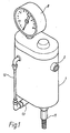
- a separator according to the present invention has a body having a casing 1 with an ellipsoid cross section with an air intake pipe 2 on one side of the casing 1.
- the intake pipe 2 is L-shaped and passes into a cylindrical protective sleeve 3 and extends into the centre of the wider end of a conical cover 4.
- the cover 4 is located above one end of the intake pipe 2 inside the casing and the outer edge of the cover 4 is protected by the sleeve 3 which is a hermitically closed structure.
- the bottom of the sleeve 3 is connected to a bore in form of a zig-zag shaped tube 5, the convoluted path of which causes further condensation.
- An L-shaped deflection plate 6 made, e.g., of iron is located opposite the outlet of the tube 5 which acts as an additional converger and separator of the water vapour and oil gas in the air.
- An air outlet pipe 7 is installed on another face of the casing 1 has a "T" shaped part inside the casing 1, the stem of the "T” extending out of the casing 1.
- a pressure meter 8 is installed at the end of the upper arm 71 of the cross piece of the "T" shaped air outlet pipe. The meter 8 is located outside the casing 1 so that the pressure of the compressed air released from the air outlet pipe 7 can be monitored.
- a plug in the form of a screw rod 9 is provided in the lower arm 72 of the cross-piece of the outlet pipe 7 so that there is only a narrow convoluted passage formed by the slot 91 of the screw rod 9 between the upper arm 71 of the outlet pipe 7 and the end of the lower arm 72 (see Fig. 3).
- the end of the lower arm 72 is sealed except for a hole.73, and is located within a cylindrical pipe 10.
- a draining control switch 11 for draining the liquid (waste liquid of mixed water and oil) accumulated inside of the casing is installed below the bottom edge of the casing 1.
- a connecting pipe 13 (Fig. 1) extends from the outer wall of the casing at the lower end thereof and is connected to a transparent high-pressure pipe 12 outside the casing 1. This pipe 12 permits observation of the volume of liquid of mixed water and oil accumulated in the air separator, so that it can be seen when it is necessary to drain the casing 1.
- the separator is connected to an air compressor and to a pneumatic tool via the air intake pipe 2 and the air outlet pipe 7 respectively.
- the air compressor compresses the air (containing a large volume of aqueous vapour and oil gas) and discharges it into the casing 1 via the air intake pipe 2 where the air contacts the conical cover 4.
- the water and oil drops flowing down to the bottom of the casing 1 will slowly accumulate into a volume which can be observed through the transparent high-pressure pipe 12 so that it can be drained from the bottom of the casing 1 by means of a draining control 11.
Landscapes
- Chemical & Material Sciences (AREA)
- Chemical Kinetics & Catalysis (AREA)
- Filtering Of Dispersed Particles In Gases (AREA)
- Separating Particles In Gases By Inertia (AREA)
- Compressor (AREA)
Claims (7)
Priority Applications (2)
| Application Number | Priority Date | Filing Date | Title |
|---|---|---|---|
| EP19820300441 EP0085206B1 (de) | 1982-01-28 | 1982-01-28 | Abscheider für komprimierten Gasen |
| DE8282300441T DE3263965D1 (en) | 1982-01-28 | 1982-01-28 | Separator for compressed air |
Applications Claiming Priority (1)
| Application Number | Priority Date | Filing Date | Title |
|---|---|---|---|
| EP19820300441 EP0085206B1 (de) | 1982-01-28 | 1982-01-28 | Abscheider für komprimierten Gasen |
Publications (2)
| Publication Number | Publication Date |
|---|---|
| EP0085206A1 EP0085206A1 (de) | 1983-08-10 |
| EP0085206B1 true EP0085206B1 (de) | 1985-06-05 |
Family
ID=8189557
Family Applications (1)
| Application Number | Title | Priority Date | Filing Date |
|---|---|---|---|
| EP19820300441 Expired EP0085206B1 (de) | 1982-01-28 | 1982-01-28 | Abscheider für komprimierten Gasen |
Country Status (2)
| Country | Link |
|---|---|
| EP (1) | EP0085206B1 (de) |
| DE (1) | DE3263965D1 (de) |
Families Citing this family (8)
| Publication number | Priority date | Publication date | Assignee | Title |
|---|---|---|---|---|
| DE3442626A1 (de) * | 1984-11-22 | 1986-05-22 | Rotorcomp Verdichter GmbH, 8000 München | Fluidabscheider, insbesondere gas/fluessigkeit-abscheider |
| US4788825A (en) * | 1988-03-02 | 1988-12-06 | Fes, Inc. | Oil separator |
| DE19508815A1 (de) * | 1995-03-11 | 1996-09-12 | Mann & Hummel Filter | Luftentölelement |
| FR2798864B1 (fr) | 1999-09-24 | 2001-12-14 | Inst Francais Du Petrole | Systeme de separation gaz/liquide intervenant dans un procede de conversion d'hydrocarbures |
| DE202008007635U1 (de) * | 2008-06-06 | 2009-10-22 | Mann+Hummel Gmbh | Luftaufbereitungsvorrichtung, insbesondere einer Luftdruckbremsanlage mit einem Abscheider für flüssige Fluide |
| CN102419268B (zh) * | 2011-12-20 | 2013-08-28 | 黑龙江省电力科学研究院 | 防凝结水倒流浸湿过滤器的固体颗粒物采集装置 |
| US10443897B2 (en) * | 2013-03-06 | 2019-10-15 | Basf Se | Pipeline system and drainage container for receiving liquid flowing through a pipeline system |
| CN117339358B (zh) * | 2023-10-27 | 2026-05-01 | 新疆天之泽化工有限公司 | 一种气液分离罐 |
Family Cites Families (2)
| Publication number | Priority date | Publication date | Assignee | Title |
|---|---|---|---|---|
| DE2340195C2 (de) * | 1973-08-08 | 1978-12-14 | Bhs-Bayerische Berg-, Huetten- Und Salzwerke Ag, 8000 Muenchen | Vorrichtung zur Naiiabscheidung von Staub |
| US4226671A (en) * | 1976-08-30 | 1980-10-07 | Phillips Petroleum Company | Venting of gases |
-
1982
- 1982-01-28 DE DE8282300441T patent/DE3263965D1/de not_active Expired
- 1982-01-28 EP EP19820300441 patent/EP0085206B1/de not_active Expired
Also Published As
| Publication number | Publication date |
|---|---|
| DE3263965D1 (en) | 1985-07-11 |
| EP0085206A1 (de) | 1983-08-10 |
Similar Documents
| Publication | Publication Date | Title |
|---|---|---|
| CA2080878C (en) | Integral oil separator and muffler | |
| EP0787245B1 (de) | Elektromechanischer flüssigkeitsniveauregler | |
| US4364756A (en) | Refrigerant suction line filter/filter-drier and method for the construction thereof | |
| US4906264A (en) | Oil separator for separating and collecting oil entrained in refrigerant | |
| EP0583770B1 (de) | Zweistufiger spiralförmiger Ölabscheider | |
| EP0276943B1 (de) | Sammler mit Kältemittel behandelnder Patrone für Autoklimaanlage | |
| US5575833A (en) | Refrigerant recycling system and apparatus | |
| US4323375A (en) | Air separator for air compressor | |
| EP0923974A1 (de) | Gas-flüssigkeitsabscheider | |
| US5553460A (en) | Horizontal oil separator/reservoir | |
| EP0085206A1 (de) | Abscheider für komprimierten Gasen | |
| EP0370521B1 (de) | In-Line-Filtereinrichtung für Druckluft | |
| EP0331607B1 (de) | Ölabscheider | |
| JPH04227010A (ja) | オイル分離方法とその装置 | |
| KR200175774Y1 (ko) | 오일 디퓨저 | |
| US6691428B1 (en) | Air dryer | |
| US1335602A (en) | Apparatus for purifying and drying steam | |
| EP0867618B1 (de) | Abblaseeinrichtung für Verdichter und damit kombinierter Feuchtigkeitsabscheider | |
| KR102210688B1 (ko) | 에어 컴프레서의 수분 분리기 | |
| US6206953B1 (en) | Condensate separator and collector | |
| EP0022352B1 (de) | Abfallsammler und mit einem solchen Abfallsammler ausgestattete Kühlanlage | |
| US2849081A (en) | Air purifier | |
| JP7750546B2 (ja) | 圧縮空気圧回路構造 | |
| EP3774468B1 (de) | Vorrichtung und verfahren zur abstrombehandlung für ein druckluftbremsenladesystem enes fahrzeugs | |
| SU1725975A1 (ru) | Фильтр-влагоотделитель |
Legal Events
| Date | Code | Title | Description |
|---|---|---|---|
| PUAI | Public reference made under article 153(3) epc to a published international application that has entered the european phase |
Free format text: ORIGINAL CODE: 0009012 |
|
| AK | Designated contracting states |
Designated state(s): DE FR GB IT |
|
| 17P | Request for examination filed |
Effective date: 19831209 |
|
| ITF | It: translation for a ep patent filed | ||
| GRAA | (expected) grant |
Free format text: ORIGINAL CODE: 0009210 |
|
| AK | Designated contracting states |
Designated state(s): DE FR GB IT |
|
| REF | Corresponds to: |
Ref document number: 3263965 Country of ref document: DE Date of ref document: 19850711 |
|
| ET | Fr: translation filed | ||
| PLBE | No opposition filed within time limit |
Free format text: ORIGINAL CODE: 0009261 |
|
| STAA | Information on the status of an ep patent application or granted ep patent |
Free format text: STATUS: NO OPPOSITION FILED WITHIN TIME LIMIT |
|
| 26N | No opposition filed | ||
| GBPC | Gb: european patent ceased through non-payment of renewal fee | ||
| PG25 | Lapsed in a contracting state [announced via postgrant information from national office to epo] |
Ref country code: FR Free format text: LAPSE BECAUSE OF NON-PAYMENT OF DUE FEES Effective date: 19880930 |
|
| PG25 | Lapsed in a contracting state [announced via postgrant information from national office to epo] |
Ref country code: DE Effective date: 19881001 |
|
| PG25 | Lapsed in a contracting state [announced via postgrant information from national office to epo] |
Ref country code: GB Free format text: LAPSE BECAUSE OF NON-PAYMENT OF DUE FEES Effective date: 19881122 |
|
| REG | Reference to a national code |
Ref country code: FR Ref legal event code: ST |