EP0085247A1 - Dispositif de réglage pour un compresseur dans un système de réfrigération - Google Patents
Dispositif de réglage pour un compresseur dans un système de réfrigération Download PDFInfo
- Publication number
- EP0085247A1 EP0085247A1 EP82306810A EP82306810A EP0085247A1 EP 0085247 A1 EP0085247 A1 EP 0085247A1 EP 82306810 A EP82306810 A EP 82306810A EP 82306810 A EP82306810 A EP 82306810A EP 0085247 A1 EP0085247 A1 EP 0085247A1
- Authority
- EP
- European Patent Office
- Prior art keywords
- temperature
- compressor
- detecting means
- capacity
- magnetic clutch
- Prior art date
- Legal status (The legal status is an assumption and is not a legal conclusion. Google has not performed a legal analysis and makes no representation as to the accuracy of the status listed.)
- Granted
Links
Images


Classifications
-
- F—MECHANICAL ENGINEERING; LIGHTING; HEATING; WEAPONS; BLASTING
- F04—POSITIVE - DISPLACEMENT MACHINES FOR LIQUIDS; PUMPS FOR LIQUIDS OR ELASTIC FLUIDS
- F04C—ROTARY-PISTON, OR OSCILLATING-PISTON, POSITIVE-DISPLACEMENT MACHINES FOR LIQUIDS; ROTARY-PISTON, OR OSCILLATING-PISTON, POSITIVE-DISPLACEMENT PUMPS
- F04C28/00—Control of, monitoring of, or safety arrangements for, pumps or pumping installations specially adapted for elastic fluids
-
- B—PERFORMING OPERATIONS; TRANSPORTING
- B60—VEHICLES IN GENERAL
- B60H—ARRANGEMENTS OF HEATING, COOLING, VENTILATING OR OTHER AIR-TREATING DEVICES SPECIALLY ADAPTED FOR PASSENGER OR GOODS SPACES OF VEHICLES
- B60H1/00—Heating, cooling or ventilating devices
- B60H1/32—Cooling devices
- B60H1/3204—Cooling devices using compression
- B60H1/3205—Control means therefor
- B60H1/3216—Control means therefor for improving a change in operation duty of a compressor in a vehicle
-
- F—MECHANICAL ENGINEERING; LIGHTING; HEATING; WEAPONS; BLASTING
- F25—REFRIGERATION OR COOLING; COMBINED HEATING AND REFRIGERATION SYSTEMS; HEAT PUMP SYSTEMS; MANUFACTURE OR STORAGE OF ICE; LIQUEFACTION SOLIDIFICATION OF GASES
- F25B—REFRIGERATION MACHINES, PLANTS OR SYSTEMS; COMBINED HEATING AND REFRIGERATION SYSTEMS; HEAT PUMP SYSTEMS
- F25B49/00—Arrangement or mounting of control or safety devices
- F25B49/02—Arrangement or mounting of control or safety devices for compression type machines, plants or systems
- F25B49/022—Compressor control arrangements
-
- G—PHYSICS
- G05—CONTROLLING; REGULATING
- G05D—SYSTEMS FOR CONTROLLING OR REGULATING NON-ELECTRIC VARIABLES
- G05D23/00—Control of temperature
- G05D23/19—Control of temperature characterised by the use of electric means
- G05D23/1927—Control of temperature characterised by the use of electric means using a plurality of sensors
- G05D23/1928—Control of temperature characterised by the use of electric means using a plurality of sensors sensing the temperature of one space
-
- G—PHYSICS
- G05—CONTROLLING; REGULATING
- G05D—SYSTEMS FOR CONTROLLING OR REGULATING NON-ELECTRIC VARIABLES
- G05D23/00—Control of temperature
- G05D23/19—Control of temperature characterised by the use of electric means
- G05D23/20—Control of temperature characterised by the use of electric means with sensing elements having variation of electric or magnetic properties with change of temperature
- G05D23/24—Control of temperature characterised by the use of electric means with sensing elements having variation of electric or magnetic properties with change of temperature the sensing element having a resistance varying with temperature, e.g. a thermistor
-
- F—MECHANICAL ENGINEERING; LIGHTING; HEATING; WEAPONS; BLASTING
- F25—REFRIGERATION OR COOLING; COMBINED HEATING AND REFRIGERATION SYSTEMS; HEAT PUMP SYSTEMS; MANUFACTURE OR STORAGE OF ICE; LIQUEFACTION SOLIDIFICATION OF GASES
- F25B—REFRIGERATION MACHINES, PLANTS OR SYSTEMS; COMBINED HEATING AND REFRIGERATION SYSTEMS; HEAT PUMP SYSTEMS
- F25B2600/00—Control issues
- F25B2600/02—Compressor control
- F25B2600/025—Compressor control by controlling speed
- F25B2600/0251—Compressor control by controlling speed with on-off operation
Definitions
- This invention relates to a control system for controlling the operation of an air conditioning system, and more particularly, to a control circuit for a variable displacement compressor In an automobile air conditioning system.
- thermal control in the room generally is accomplished by the intermittent operation of the air conditioning compressor through a magnetic clutch or motor.
- the magnetic clutch or motor is connected to the compressor and activated by a signal from a thermostat disposed in the room.
- the compressor In air conditioning systems for automobiles, the compressor usually i3 driven by the engine of the automobile. Since the r.p.m. of the automobile engine changes continuously, the rotation frequency of the compressor also changes which in turn rapidly changes the cooling capacity of the air conditioner.
- Automobile air conditioners generally are designed so that when the compressor is driven by the engine at normal driving speed, the air conditioner operates at optimum capacity. Therefore, when the compressor is driven by the engine at lower operating speed, or during idling, the cooling capacity of the air conditioner is insufficient in comparison with the refrigerating or cooling load. Also, when the compressor is driven by the engine at high operating speed, the cooling capacity is higher than necessary.
- One known mechanism for controlling the excessive cooling capacity of an air conditioner operates by heating part of the cool air generated by the air conditioner. Part of the cool air from the evaporator of the air conditioner passes a heating unit which heats the cool air and this heated air is mixed with the remaining cool air to control the temperature of the air which is blown into the room or compartment. In this mechanism, the ratio of cooling capacity to heating capacity is controlled in response to driving frequency. This mechanism for controlling air temperature is complicated and considerable energy is spent to reheat the cool air by using engine power.
- the magnetic clutch which is disposed on the compressor and connected between the engine and the compressor to transmit rotating motion is intermittently operated to control the operation of the compressor.
- the magnetic clutch since the magnetic clutch may be operated at high rotation frequency, a sudden force is generated at the moment the clutch is engaged and this sudden force is transmitted to the engine and the compressor. Also, the temperature of the air blown into the compartment drastically changes upon operation of the compressor.
- the present invention is directed to a control device for a compressor in a refrigerating or air conditioning system.
- the compressor includes a variable displacement device which changes the capacity of the compressor and a magnetic clutch which operates the compressor In response to an external drive mechanism.
- the control device includes a magnetic clutch control circuit which controls the operation of the magnetic clutch and a capacity control circuit which controls the operation of the variable displacement device.
- the magnetic clutch control circuit and the capacity control circuit include thermistors mounted adjacent each other on the evaporator of the air conditioning system to detect the temperature of the cool air blown from the evaporator.
- the thermistor in the capacity control circuit has a higher thermal sensitivity, i.e., a different thermal response characteristic, than the thermistor in the magnetic clutch control circuit.
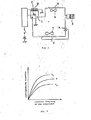
- FIG. i the basic construction of an air conditioning system, particularly, an automobile air conditioning system, is shown.
- This air conditioning system comprises compressor i, condenser 2 , receiver and dryer 3, thermostatic expansion device or valve 4 and evaporator 5. These five basic components are coupled in series to form a conventional closed vapor cycle refrigeration circuit.
- Refrigerant gas is compressed in compressor and supplied to condenser 2 where it is condensed to liquid refrigerant and cooled by forced ventilation of fan 6.
- the liquid refrigerant is accumulated in receiver and dryer 3 , which removes the moisture and metal chips in the liquid refrigerant.
- the liquid refrigerant within receiver and dryer 3 is delivered to thermostatic expansion valve 4 .
- the refrigerant expands as it flows through valve 4 and emerges as a two-phase mixture of liquid and gas, but primarily liquid.
- evaporator 5 acts as a heat exchanger in conjunction with blower 7 which supplies air to the vehicle compartment by blower 7 , heat is transferred from the incoming air to the refrigerant and the entirety of the refrigerant vaporizes and assumes its gaseous state.
- the refrigerant gas at the evaporator outlet then is passed to the suction inlet of compressor I.
- Compressor I which is shown in block diagram form in Figure I, is a variable displacement compressor.
- compressor i is a scroll type compressor Including a variable displacement device as shown in copending European patent application No. 82301205.9 filed on March 9, 1982 and copending European patent application No. 82 306702.0 filed on December 15, 1982.
- Compressor i is controlled by operation of magnetic clutch 8 and variable displacement device 9 which changes the refrigerating capacity thereof.
- Magnetic clutch 8 and variable displacement device 9 are controlled by operation of compressor control circuit 10, which Is described in further detail below in connection with Figure 3 .
- Compressor control circuit 10 is connected to voltage source E by on/off switch S.
- compressor i includes a variable displacement device which is capable of changing the refrigerating or cooling capacity of the compressor.
- the capacity of the compressor shown in Figure I can be changed to one of two conditions, C 1 or C 2 , as shown in Figure 2 .
- curve C is the normal capacity of prior art compressors.
- the variable displacement device of compressor 1 includes at least one valve as shown in patent applications Nos. 82301205.9 and 82306702.0 and this valve is controlled by solenoid 9 shown in Figure i. Solenoid 9 is connected to voltage source E through compressor control circuit 10 and main air conditioning on/off switch S.
- the compressor control circuit includes a magnetic clutch control circuit and a capacity control circuit.
- the magnetic clutch control circuit includes an input circuit formed by voltage comparator 12 and a voltage divider formed by thermistor TH 1 and resistor R 1 .
- the voltage divider supplies voltage Vb to the non-inverting input terminal (+) of comparator 12.
- Thermistor Th 1 is mounted on the surface of the cool air outlet of evaporator 5 to detect the temperature of the cool air blown from evaporator 5.
- the voltage Vb at point b of compressor control circuit 10 varies in accordance with the temperature of the cool air blown from evaporator 5 so that voltage signal Vb represents the temperature of the cool air at evaporator 5.
- This temperature voltage signal Vb is compared at comparator 12 with reference voltage Va which is generated by another voltage divider formed by variable resistance VR and resistors R 6 , R 7 and Rg.
- Reference voltage Va which is applied to an inverting input terminal (-) of comparator 12 , corresponds to predetermined temperature T 2 .
- Reference voltage Va can be changed by varying the resistance of variable resistor VR, I.e., predetermined temperature T 2 can be changed by the user of the air conditioner.
- the output of comparator 12 is coupled to the base of NPN switching transistor Tr 1 to control the operation of magnetic clutch 8.
- Transistor Tr 1 is biased by biasing resistors R 11 and R 12 .
- the coil of relay Ry 1 is connected to the collector of transistor Tr l and the operating contact of relay Ry 1 is connected in series with coil Mg of electromagnetic clutch 6.
- relay Ry 1 is energized so that electromagnetic coil Mg of clutch 8 is energized to operate compressor 1.
- the primary elements of the magnetic clutch control circuit are thermistor Th 1 , comparator 12, switching transistor Tr 1 , relay Ry 1 and magnetic clutch coil Mg.
- Feedback resistor R 3 also is connected to comparator 12 so that the input-output response has a hysteresis effect.
- the output of comparator 12 changes from a high level to a low level when temperature voltage signal Vb equals reference voltage Va.
- the output of comparator 12 does not immediately change from a low level to a high level, but at a time when the temperature voltage signal Vb is higher than reference voltage Va by a certain amount which is determined by the resistance of resistor R 3 .
- the output response of comparator 12 to temperature has a hysteresis effect.
- Compressor control circuit 10 also includes a capacity control circuit formed in part by tnermistor ln 2 .
- Thermistor Th2 is mounted on the surface of the cool air outlet of evaporator 5 adjacent thermistor Th 1 to detect the temperature of the cool air blown from evaporator 5.
- Thermistor Th z has a different thermal response characteristic than thermistor Th 1 as shown by Figure 4 .
- the characteristic thermal responses of thermistors Th 1 and Th 2 arc shown as curves Tth 1 and Tth 2 , respectively. These curves indicate that voltage signals Vb and Vd arc different and that thermistor Th 2 has a higher thermal sensitivity than thermistor Th 1 .
- a voltage divider is formed by thermistor Th 2 and resistor R 2 in order to supply a voltage signal Vd to a non-inverting input terminal (+) of comparator t 3 .
- the voltage signal Vd at point d varies in accordance with the temperature nf the hlnwn air from evaporator 5 so that voltage signal Vd represents the temperature of the blown or cool air.
- the temperature voltage signal Vd is compared at comparator 13 with reference voltage Vc which is generated by the voltage divider formed by variable resistance VR and resistors R 6 , R 7 and R 8 .
- Comparator 13 also includes a feedback resistor R 4 which corresponds to feedback resistor R 3 of comparator 12 .
- Reference voltage Vc which is applied to an Inverting input terminal (-) of comparator 13 , corresponds to predetermined temperature T 3 .
- the output of comparator 13 is coupled to the base of PNP switching transistor Tr 2 to control the operation of at least one valve in a variable displacement device in compressor i of Figure i.
- the coil of relay Ry 2 is connected to the collector of transistor Tr 2 and the operating contact of relay Ry 2 is connected in series with solenoid valve SV of variable displacement device 9 .
- Transistor Tr 2 is biased by biasing resistors R 9 and R 10 .
- relay R y2 When transistor Tr 2 is conductive, relay R y2 is energized so that solenoid valve SV is energized and to change the capacity of compressor i from large volume C 1 to small volume C 2 .
- the primary elements of the capacity control circuit are thermistor Th 2 , comparator 13 , switching transistor Tr 2 , relay Ry 2 and solenoid valve SV of variable displacement device 9.
- the temperature voltage signal Vd usually is lower than the reference voltage Vc until the output of comparator 11 changes to a high voltage level as further described below.
- solenoid valve SV continues to operate compressor 1 at small volume C 2 .
- the voltage Vf at point f of the circuit of Figure 3 which corresponds to temperature voltage signal Vb, is applied to non-inverting input terminal (+) of comparator 11 and compared at comparator 11 with reference voltage Ve, which corresponds to predetermined temperature T1.
- the output of comparator 11 is coupled via diode D 1 to the non-inverting input terminal (+) of comparator 13 .
- the output of comparator 13 also changes to a high voltage level irrespective of the influence of temperature voltage signal Yd.
- the high voltage level output of comparator 13 changes the capacity of compressor 1 from small volume C 2 to large volume C l .
- Figures 5 and 6 also illustrate the difference in thermal response of thermistors Th I and Th 2 as previously described in connection with Figure 4.
- Thermistor Th 2 has a higher thermal sensitivity than thermistor Th 1 so that the rate of change in temperature Tth 2 detected by thermistor Th 2 is greater than the rate of change in temperature Tth 1 detected by thermistor Th 1 .
- the on/off condition of the compressor is controlled by the compressor control circuit in response to the temperature Tth 1 detected by the less sensitive thermistor Th l .
- the refrigerating capacity of compressor i is larger than the refrigerator or cooling load of the air conditioner, a large difference occurs between the temperatures detected by Th I and Th 2 at time t i as shown in Figure 5.
- the operating time of the compressor is shorter than the non-operating time, i.e., the activity rate of the compressor is low.
- the temperature Tth 2 goes below predetermined temperature T3, which causes the capacity control circuit to change the capacity of the compressor from large volume C 1 to small volume C 2 by operation of the variable displacement device.
Landscapes
- Engineering & Computer Science (AREA)
- Physics & Mathematics (AREA)
- Mechanical Engineering (AREA)
- General Physics & Mathematics (AREA)
- Automation & Control Theory (AREA)
- Thermal Sciences (AREA)
- General Engineering & Computer Science (AREA)
- Control Of Positive-Displacement Pumps (AREA)
- Air-Conditioning For Vehicles (AREA)
Applications Claiming Priority (2)
| Application Number | Priority Date | Filing Date | Title |
|---|---|---|---|
| JP190759/81U | 1981-12-21 | ||
| JP1981190759U JPS5896468U (ja) | 1981-12-21 | 1981-12-21 | 空調装置の制御装置 |
Publications (2)
| Publication Number | Publication Date |
|---|---|
| EP0085247A1 true EP0085247A1 (fr) | 1983-08-10 |
| EP0085247B1 EP0085247B1 (fr) | 1986-07-23 |
Family
ID=16263253
Family Applications (1)
| Application Number | Title | Priority Date | Filing Date |
|---|---|---|---|
| EP82306810A Expired EP0085247B1 (fr) | 1981-12-21 | 1982-12-20 | Dispositif de réglage pour un compresseur dans un système de réfrigération |
Country Status (5)
| Country | Link |
|---|---|
| US (1) | US4485635A (fr) |
| EP (1) | EP0085247B1 (fr) |
| JP (1) | JPS5896468U (fr) |
| AU (1) | AU560801B2 (fr) |
| DE (1) | DE3272219D1 (fr) |
Cited By (1)
| Publication number | Priority date | Publication date | Assignee | Title |
|---|---|---|---|---|
| EP0194029A1 (fr) * | 1985-02-01 | 1986-09-10 | Sanden Corporation | Procédé et appareil pour régler la capacité d'un compresseur à capacité variable |
Families Citing this family (21)
| Publication number | Priority date | Publication date | Assignee | Title |
|---|---|---|---|---|
| JPS6172964A (ja) * | 1984-09-14 | 1986-04-15 | 株式会社デンソー | 冷凍サイクル制御装置 |
| JPS62184916A (ja) * | 1986-02-07 | 1987-08-13 | Sanden Corp | 可変容量圧縮機を有する冷房装置 |
| US4694228A (en) * | 1986-03-21 | 1987-09-15 | Rca Corporation | Compensation circuit for control system providing pulse width modulated drive signal |
| JPS6370421U (fr) * | 1986-10-29 | 1988-05-11 | ||
| EP0275045B1 (fr) * | 1987-01-10 | 1993-07-07 | Sanden Corporation | Appareil pour commander la puissance d'un compresseur muni d'une puissance variable |
| US4841734A (en) * | 1987-11-12 | 1989-06-27 | Eaton Corporation | Indicating refrigerant liquid saturation point |
| US5177973A (en) * | 1991-03-19 | 1993-01-12 | Ranco Incorporated Of Delaware | Refrigeration system subcooling flow control valve |
| US5156017A (en) * | 1991-03-19 | 1992-10-20 | Ranco Incorporated Of Delaware | Refrigeration system subcooling flow control valve |
| DE69217300T2 (de) * | 1991-09-02 | 1997-06-26 | Sanden Corp | Fahrzeugklimaanlage mit einem, eine fremdgesteuert einstellbare Verdrängungseinrichtung aufweisenden, Kühlflüssigkeitskompressor |
| US5293755A (en) * | 1992-12-09 | 1994-03-15 | Thomas Charles V | Air conditioning load management control system |
| JP2000142080A (ja) | 1998-11-05 | 2000-05-23 | Sanden Corp | 建設車両用空調装置 |
| JP4327331B2 (ja) | 2000-04-21 | 2009-09-09 | サンデン株式会社 | 車両空調装置用可変容量斜板式圧縮機の制御装置 |
| DE10062948C2 (de) * | 2000-12-16 | 2002-11-14 | Eaton Fluid Power Gmbh | Kältemaschine mit kontrollierter Kältemittelphase vor dem Verdichter |
| US6560978B2 (en) | 2000-12-29 | 2003-05-13 | Thermo King Corporation | Transport temperature control system having an increased heating capacity and a method of providing the same |
| US6487869B1 (en) | 2001-11-06 | 2002-12-03 | Themo King Corporation | Compressor capacity control system |
| US6769265B1 (en) | 2003-03-12 | 2004-08-03 | Maytag Corporation | Variable speed refrigeration system |
| US7490480B2 (en) * | 2003-03-14 | 2009-02-17 | Maytag Corporation | Variable speed refrigeration system |
| US7080521B2 (en) * | 2004-08-31 | 2006-07-25 | Thermo King Corporation | Mobile refrigeration system and control |
| JP5786476B2 (ja) * | 2011-06-14 | 2015-09-30 | 日産自動車株式会社 | 車両用空調装置 |
| GB2512129B (en) * | 2013-03-21 | 2016-01-13 | Enigin Plc | Force-cooled air-conditioning system |
| EP3282202B1 (fr) * | 2015-04-07 | 2021-09-22 | Hitachi-Johnson Controls Air Conditioning, Inc. | Climatiseur |
Citations (3)
| Publication number | Priority date | Publication date | Assignee | Title |
|---|---|---|---|---|
| CH173493A (de) * | 1933-09-29 | 1934-11-30 | Sulzer Ag | Verdichter mit sichelförmigem Arbeitsraum, insbesondere bei Kältemaschinen. |
| DE1403516A1 (de) * | 1960-02-26 | 1968-10-31 | Linde Ag | Verfahren zur Regelung der Foerdermenge von Drehkolbenverdichtern der Vielzellenbauart und Vorrichtung zur Durchfuehrung des Verfahrens |
| US3924972A (en) * | 1974-10-29 | 1975-12-09 | Vilter Manufacturing Corp | Control means for a variable capacity rotary screw compressor |
Family Cites Families (4)
| Publication number | Priority date | Publication date | Assignee | Title |
|---|---|---|---|---|
| US2319130A (en) * | 1941-03-05 | 1943-05-11 | B F Sturtevant Co | Refrigeration control for air conditioned passenger vehicles |
| DE2635901C2 (de) * | 1976-08-10 | 1983-06-01 | Robert Bosch Gmbh, 7000 Stuttgart | Einrichtung zum Regeln der Temperatur eines Raumes |
| US4187093A (en) * | 1978-02-01 | 1980-02-05 | Boratgis James P | Refrigerator electronic temperature control and malfunction signal apparatus |
| US4325224A (en) * | 1980-04-29 | 1982-04-20 | Thermo King Corp. | Method and apparatus for transport refrigeration system control |
-
1981
- 1981-12-21 JP JP1981190759U patent/JPS5896468U/ja active Granted
-
1982
- 1982-12-20 EP EP82306810A patent/EP0085247B1/fr not_active Expired
- 1982-12-20 DE DE8282306810T patent/DE3272219D1/de not_active Expired
- 1982-12-21 US US06/451,941 patent/US4485635A/en not_active Expired - Fee Related
- 1982-12-21 AU AU91729/82A patent/AU560801B2/en not_active Ceased
Patent Citations (3)
| Publication number | Priority date | Publication date | Assignee | Title |
|---|---|---|---|---|
| CH173493A (de) * | 1933-09-29 | 1934-11-30 | Sulzer Ag | Verdichter mit sichelförmigem Arbeitsraum, insbesondere bei Kältemaschinen. |
| DE1403516A1 (de) * | 1960-02-26 | 1968-10-31 | Linde Ag | Verfahren zur Regelung der Foerdermenge von Drehkolbenverdichtern der Vielzellenbauart und Vorrichtung zur Durchfuehrung des Verfahrens |
| US3924972A (en) * | 1974-10-29 | 1975-12-09 | Vilter Manufacturing Corp | Control means for a variable capacity rotary screw compressor |
Cited By (1)
| Publication number | Priority date | Publication date | Assignee | Title |
|---|---|---|---|---|
| EP0194029A1 (fr) * | 1985-02-01 | 1986-09-10 | Sanden Corporation | Procédé et appareil pour régler la capacité d'un compresseur à capacité variable |
Also Published As
| Publication number | Publication date |
|---|---|
| US4485635A (en) | 1984-12-04 |
| JPS6230686Y2 (fr) | 1987-08-06 |
| EP0085247B1 (fr) | 1986-07-23 |
| DE3272219D1 (en) | 1986-08-28 |
| AU560801B2 (en) | 1987-04-16 |
| JPS5896468U (ja) | 1983-06-30 |
| AU9172982A (en) | 1983-06-30 |
Similar Documents
| Publication | Publication Date | Title |
|---|---|---|
| US4485635A (en) | Control device for a compressor in a refrigerating system | |
| EP0085246A1 (fr) | Circuit de réglage pour un compresseur à déplacement variable pour le contitionnement d'air | |
| US6523361B2 (en) | Air conditioning systems | |
| CA1252177A (fr) | Dispositif regulateur de la capacite d'un compresseur a volume variable | |
| US4539821A (en) | Capacity control device for controlling a variable displacement compressor in an air conditioning system | |
| US5568732A (en) | Air conditioning apparatus and method of controlling same | |
| US4848100A (en) | Controlling refrigeration | |
| US6526771B2 (en) | Freezing cycle apparatus | |
| US5289692A (en) | Apparatus and method for mass flow control of a working fluid | |
| US5694783A (en) | Vapor compression refrigeration system | |
| US4498311A (en) | Control device for a variable displacement compressor in an air conditioning system | |
| US4843834A (en) | Device for controlling capacity of variable capacity compressor | |
| JPH04217750A (ja) | 冷却装置のための制御装置およびその制御方法 | |
| CN100580250C (zh) | 压缩机容量控制系统和制冷循环系统 | |
| EP0085245B1 (fr) | Dispositif de réglage de capacité pour un compresseur dans un système de réfrigération | |
| EP1362725B1 (fr) | Dispositif de contrôle | |
| EP0119341B1 (fr) | Dispositif de commande pour un compresseur à déplacement variable dans une installation d'air conditionné | |
| US5216892A (en) | Compressor clutch cut-out control in an automotive air conditioning system | |
| JP4706671B2 (ja) | 電磁弁の制御装置 | |
| EP0118573A1 (fr) | Dispositif de commande de capacité pour un compresseur à déplacement variable dans un système d'air conditionné | |
| KR100237927B1 (ko) | 공기 조화기 구동 방법 | |
| KR100230433B1 (ko) | 차량용 공기 조화 장치 | |
| JPH05240493A (ja) | 空気調和機 | |
| JPS6321457A (ja) | 冷凍サイクル装置 | |
| JPS6151218B2 (fr) |
Legal Events
| Date | Code | Title | Description |
|---|---|---|---|
| PUAI | Public reference made under article 153(3) epc to a published international application that has entered the european phase |
Free format text: ORIGINAL CODE: 0009012 |
|
| AK | Designated contracting states |
Designated state(s): DE FR GB IT SE |
|
| 17P | Request for examination filed |
Effective date: 19840208 |
|
| ITF | It: translation for a ep patent filed | ||
| GRAA | (expected) grant |
Free format text: ORIGINAL CODE: 0009210 |
|
| AK | Designated contracting states |
Kind code of ref document: B1 Designated state(s): DE FR GB IT SE |
|
| REF | Corresponds to: |
Ref document number: 3272219 Country of ref document: DE Date of ref document: 19860828 |
|
| ET | Fr: translation filed | ||
| PLBI | Opposition filed |
Free format text: ORIGINAL CODE: 0009260 |
|
| 26 | Opposition filed |
Opponent name: ROBERT BOSCH GMBH Effective date: 19870422 |
|
| PLBM | Termination of opposition procedure: date of legal effect published |
Free format text: ORIGINAL CODE: 0009276 |
|
| STAA | Information on the status of an ep patent application or granted ep patent |
Free format text: STATUS: OPPOSITION PROCEDURE CLOSED |
|
| 27C | Opposition proceedings terminated |
Effective date: 19881106 |
|
| ITTA | It: last paid annual fee | ||
| PGFP | Annual fee paid to national office [announced via postgrant information from national office to epo] |
Ref country code: GB Payment date: 19921208 Year of fee payment: 11 |
|
| PGFP | Annual fee paid to national office [announced via postgrant information from national office to epo] |
Ref country code: FR Payment date: 19921209 Year of fee payment: 11 |
|
| PGFP | Annual fee paid to national office [announced via postgrant information from national office to epo] |
Ref country code: SE Payment date: 19921214 Year of fee payment: 11 |
|
| PGFP | Annual fee paid to national office [announced via postgrant information from national office to epo] |
Ref country code: DE Payment date: 19930115 Year of fee payment: 11 |
|
| PG25 | Lapsed in a contracting state [announced via postgrant information from national office to epo] |
Ref country code: GB Effective date: 19931220 |
|
| PG25 | Lapsed in a contracting state [announced via postgrant information from national office to epo] |
Ref country code: SE Effective date: 19931221 |
|
| GBPC | Gb: european patent ceased through non-payment of renewal fee |
Effective date: 19931220 |
|
| PG25 | Lapsed in a contracting state [announced via postgrant information from national office to epo] |
Ref country code: FR Effective date: 19940831 |
|
| PG25 | Lapsed in a contracting state [announced via postgrant information from national office to epo] |
Ref country code: DE Effective date: 19940901 |
|
| REG | Reference to a national code |
Ref country code: FR Ref legal event code: ST |
|
| EUG | Se: european patent has lapsed |
Ref document number: 82306810.1 Effective date: 19940710 |