EP0119341B1 - Dispositif de commande pour un compresseur à déplacement variable dans une installation d'air conditionné - Google Patents
Dispositif de commande pour un compresseur à déplacement variable dans une installation d'air conditionné Download PDFInfo
- Publication number
- EP0119341B1 EP0119341B1 EP83301572A EP83301572A EP0119341B1 EP 0119341 B1 EP0119341 B1 EP 0119341B1 EP 83301572 A EP83301572 A EP 83301572A EP 83301572 A EP83301572 A EP 83301572A EP 0119341 B1 EP0119341 B1 EP 0119341B1
- Authority
- EP
- European Patent Office
- Prior art keywords
- compressor
- comparator
- temperature
- rate
- cooling capacity
- Prior art date
- Legal status (The legal status is an assumption and is not a legal conclusion. Google has not performed a legal analysis and makes no representation as to the accuracy of the status listed.)
- Expired
Links
Images


Classifications
-
- B—PERFORMING OPERATIONS; TRANSPORTING
- B60—VEHICLES IN GENERAL
- B60H—ARRANGEMENTS OF HEATING, COOLING, VENTILATING OR OTHER AIR-TREATING DEVICES SPECIALLY ADAPTED FOR PASSENGER OR GOODS SPACES OF VEHICLES
- B60H1/00—Heating, cooling or ventilating devices
- B60H1/32—Cooling devices
- B60H1/3204—Cooling devices using compression
- B60H1/3205—Control means therefor
- B60H1/3216—Control means therefor for improving a change in operation duty of a compressor in a vehicle
-
- F—MECHANICAL ENGINEERING; LIGHTING; HEATING; WEAPONS; BLASTING
- F25—REFRIGERATION OR COOLING; COMBINED HEATING AND REFRIGERATION SYSTEMS; HEAT PUMP SYSTEMS; MANUFACTURE OR STORAGE OF ICE; LIQUEFACTION SOLIDIFICATION OF GASES
- F25B—REFRIGERATION MACHINES, PLANTS OR SYSTEMS; COMBINED HEATING AND REFRIGERATION SYSTEMS; HEAT PUMP SYSTEMS
- F25B49/00—Arrangement or mounting of control or safety devices
- F25B49/02—Arrangement or mounting of control or safety devices for compression type machines, plants or systems
- F25B49/022—Compressor control arrangements
-
- G—PHYSICS
- G05—CONTROLLING; REGULATING
- G05D—SYSTEMS FOR CONTROLLING OR REGULATING NON-ELECTRIC VARIABLES
- G05D23/00—Control of temperature
- G05D23/19—Control of temperature characterised by the use of electric means
- G05D23/1906—Control of temperature characterised by the use of electric means using an analogue comparing device
- G05D23/1912—Control of temperature characterised by the use of electric means using an analogue comparing device whose output amplitude can take more than two discrete values
-
- G—PHYSICS
- G05—CONTROLLING; REGULATING
- G05D—SYSTEMS FOR CONTROLLING OR REGULATING NON-ELECTRIC VARIABLES
- G05D23/00—Control of temperature
- G05D23/19—Control of temperature characterised by the use of electric means
- G05D23/20—Control of temperature characterised by the use of electric means with sensing elements having variation of electric or magnetic properties with change of temperature
- G05D23/24—Control of temperature characterised by the use of electric means with sensing elements having variation of electric or magnetic properties with change of temperature the sensing element having a resistance varying with temperature, e.g. a thermistor
-
- B—PERFORMING OPERATIONS; TRANSPORTING
- B60—VEHICLES IN GENERAL
- B60H—ARRANGEMENTS OF HEATING, COOLING, VENTILATING OR OTHER AIR-TREATING DEVICES SPECIALLY ADAPTED FOR PASSENGER OR GOODS SPACES OF VEHICLES
- B60H1/00—Heating, cooling or ventilating devices
- B60H1/32—Cooling devices
- B60H2001/3236—Cooling devices information from a variable is obtained
- B60H2001/3238—Cooling devices information from a variable is obtained related to the operation of the compressor
-
- B—PERFORMING OPERATIONS; TRANSPORTING
- B60—VEHICLES IN GENERAL
- B60H—ARRANGEMENTS OF HEATING, COOLING, VENTILATING OR OTHER AIR-TREATING DEVICES SPECIALLY ADAPTED FOR PASSENGER OR GOODS SPACES OF VEHICLES
- B60H1/00—Heating, cooling or ventilating devices
- B60H1/32—Cooling devices
- B60H2001/3269—Cooling devices output of a control signal
- B60H2001/327—Cooling devices output of a control signal related to a compressing unit
-
- F—MECHANICAL ENGINEERING; LIGHTING; HEATING; WEAPONS; BLASTING
- F25—REFRIGERATION OR COOLING; COMBINED HEATING AND REFRIGERATION SYSTEMS; HEAT PUMP SYSTEMS; MANUFACTURE OR STORAGE OF ICE; LIQUEFACTION SOLIDIFICATION OF GASES
- F25B—REFRIGERATION MACHINES, PLANTS OR SYSTEMS; COMBINED HEATING AND REFRIGERATION SYSTEMS; HEAT PUMP SYSTEMS
- F25B2600/00—Control issues
- F25B2600/02—Compressor control
- F25B2600/025—Compressor control by controlling speed
- F25B2600/0251—Compressor control by controlling speed with on-off operation
Definitions
- This invention relates generally to a device for controlling the operation of an air conditioning system, and more particularly, to an electronic control circuit for a variable displacement compressor in an automobile air conditioning system.
- this invention relates to a control device for an air conditioning system having a refrigerant compressor, a condenser, a thermostatic expansion device, an evaporator and a blower to blow cool air from the evaporator, the compressor having a magnetic clutch to drive the compressor and a variable displacement device to change the cooling capacity of the air conditioning system.
- the air conditioning compressor is driven by a motor, either directly or through a magnetic clutch.
- Thermal control in the room or compartment is accomplished by the intermittent operation of the magnetic clutch or motor by a signal from a thermostat disposed in the room.
- the supplemental cooling capacity of the air conditioner need not be as large for maintaining the desired temperature in the room. Therefore, after the room has been cooled to the desired temperature, conventional air conditioning compressors are intermittently operated in response to the thermostat signal. Compressors having large cooling capacities are operated even more intermittently because of the high amounts of energy required to drive such compressors.
- the compressor In an air conditioning system for automobiles, the compressor is usually driven by the automobile engine. Because the r.p.m. of the automobile engine changes continuously, the rotation frequency of the compressor changes accordingly, resulting in rapid changes in the cooling capacity of the air conditioner.
- Automobile air conditioners are generally designed so that when the compressor is driven by the engine at normal driving speeds, the air condition operates at optimum capacity. Therefore, when the compressor is driven by the engine at lower operating speeds, or when the engine is idling, the cooling capcity of the air conditioner is insufficient to maintain adequate cooling of the vehicle. Conversely, when the compressor is driven at high operating speeds by the engine, cooling capacity is more than necessary.
- One known device for controlling the excessive cooling capacity of air conditioning systems operates by reheating some of the cooled air generated by the air conditioner. Part of the air from the evaporator of the air conditioner is reheated in a heating unit. The reheated air is mixed with the remaining cooled air to control the temperature of the air which is ultimately blown into the room or compartment. In this device, the ratio of cooling capacity to heating capacity is controlled in response to the r.p.m. of the automobile engine.
- the above-described device for controlling air temperature is complicated and considerable energy is wasted in reheating the cooled air.
- the magnetic clutch connecting the compressor to the driving engine or motor is intermittently operated to control the operation of the compressor.
- the magnetic clutch is often required to engage the driving engine at high operating speeds, sudden and deleterious forces are generated at the moment the clutch is engaged and are transmitted to the engine and compressor.
- the temperature of the air which is blown into the room or compartment also drastically changes upon engagement of the clutch and operation of the compressor.
- DE-A-3 210 884 discloses an automobile air conditioner having a compressor which is driven by the automobile engine via an electro-magnetic clutch, a receiver, an expansion valve and an evaporator.
- the compressor is of variable capacity or discharge type and including displacement varying members for varying the capacity or displacement of the compressor.
- a thermistor is provided for detecting the temperature of air immediately downstream of the evaporator. Signals from the thermistor are applied to an electric circuit whose output is connected to a servo motor.
- the servo motor drives the displacement varying members so as to vary the capacity of the compressor in accordance with the temperature sensed by the thermistor.
- a control device for an air conditioning system including a refrigerant compressor, a condenser, a thermostatic expansion device, an evaporator and a blower to blow cool air from said evaporator, said compressor having a magnetic clutch to drive said compressor and a variable displacement device to change the cooling capacity of the air conditioning system, and said control device comprising a voltage source and a magnetic clutch control means connected to said voltage source for actuating said magnetic clutch to drive said compressor, characterised by a cooling capacity control means connected to said voltage source for actuating said variable displacement device to thereby change the cooling capacity of the air conditioning system in response to the rate of operation of said compressor.
- One embodiment of the present invention is a control circuit for a compressor in a refrigerating or air conditioning system.
- the compressor includes a variable displacement device for changing the cooling capacity of the compressor and a magnetic clutch which operates to engage the compressor to an external drive mechanism.
- the control circuit includes a cooling capacity control circuit which controls the operation of the variable displacement device and a magnetic clutch control circuit which controls the operation of the magnetic clutch.
- the cooling capacity control circuit operates to reduce the cooling capacity of the compressor in response to a comparison of the rate of operation of the compressor with a predetermined rate of operation of the compressor. For example, when the rate of operation of the compressor is below the predetermined rate, the cooling capacity is reduced to a more efficient and economical level.
- the cooling capacity control circuit also operates to increase the cooling capacity of the compressor in response to a comparison of the temperature of the blown air Tth with a predetermined temperature. Accordingly, when the cooling capacity of the compressor is insufficient to satisfy the required cooling load, as indicated by a rise in temperature, cooling capacity is increased.
- the control circuit of this invention also includes a magnetic clutch control circuit which controls the operation of the magnetic clutch in response to a comparison of the blown air Tth with a another predetermined temperature. When temperature Tth reaches the predetermined temperature, the room or compartment is at the desired temperature and the compressor may be turned off. Therefore, by turning the compressor on and off and by varying the cooling capacity, the control device of the present invention adjusts the rate of operation of the compressor to achieve optimum operating efficiency.
- the control device of the present invention permits an air conditioning system to be operated in a very economical and efficient manner.
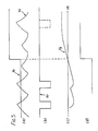
- FIG. 1 there is shown a graph of the temperature variations of the air blown by a conventional air conditioning system.
- the air conditioning system When the air conditioning system is first turned on and the compressor begins to operate, air having relatively high temperature Tth is blown into the room or compartment. As the compressor continues to operate, temperature Tth gradually falls to predetermined temperature T 2 . At this point, the compressor stops operating and temperature Tth begins to rise. When temperature Tth reaches predetermined temperature T 1 , the compressor begins operating again. Intermittent operation of the compressor continues as described above so that the temperature of the blown air is kept within the range T,-T 2 , as shown in Figure 1.
- K o the rate of operation of the compressor
- t the length of time that the compressor is in an operating state
- t 2 is the length of time that the compressor is in a non-operating state.
- the air conditioning system comprises a compressor as generally indicated by reference number 1.
- Compressor 1 includes magnetic clutch 8 and variable displacement device 9 which are controlled by control circuit 10, as will be explained in greater detail below.
- the air conditioning system shown in Figure 2 further comprises condensor 2 and its associated fan 6, receiver and dryer 3, thermostatic expansion device or valve 4 and evaporator 5 and its associated fan 7. These basic components are coupled in series to form a conventional refrigeration circuit.
- Refrigerant gas is compressed in compressor 1 and supplied to condensor 2 where it is condensed to liquid refrigerant and cooled by the forced ventilation of fan 6.
- the liquid refrigerant is accumulated in receiver and dryer 3, which removes the moisture and metal chips from the liquid refrigerant.
- the liquid refrigerant within the receiver and dryer 3 is delivered to thermostatic expansion value 4.
- the refrigerant expands as it flows through valve 4 and emerges as a two-part mixture of liquid and gas, but primarily liquid.
- evaporator 5 acts as a heat exchanger in conjunction with fan 7 which supplies air to the vehicle compartment, heat is transferred from the incoming air to the refrigerant and the entirety of the refrigerant vaporizes to a gaseous state.
- the refrigerant gas at the evaporator outlet is then passed to the suction inlet of compressor 1.
- compressor 1 is a scroll-type compressor including variable displacement device 9 as shown in co-pending Patent Application No. 82301205.9, filed on March 9, 1982, and co-pending Patent Application No. 82306702.0, filed on December 15, 1982, now EP-A-00 60140 and EP-A-0 113 786.
- Compressor 1 is controlled by the operation of magnetic clutch 8 which controls engagement of the driving means and by the operation of variable displacement device 9 which changes the cooling capacity of the compressor.
- Magnetic clutch 8 and variable displacement device 9 are controlled by the operation of control circuit 10, which is described in further detail below in connection with Figure 4.
- compressor 1 includes variable displacement device 9 which is capable of changing the cooling capacity of the compressor.
- the cooling capacity of the compressor shown in Figure 1 can be changed to one of two levels; i.e., CC1 or CC2, as shown in Figure 3.
- Variable displacement device 9 of compressor 1 includes at least one valve as shown in Patent Applications Nos. 82301205.9 and 82306702.0, now EP-A-00 60140 and EP-A-0 113 786. This value is controlled by a solenoid which is in turn controlled by control circuit 10 as will be explained with reference to Figure 4.
- Control circuit 10 comprises a magnetic clutch control circuit, a cooling capacity control circuit and power supply E which supplies electrical power through switch S to control circuit 10 and to magnetic clutch 8 and variable displacement device 9 as shown.
- the magnetic clutch control circuit includes an input circuit formed by voltage comparator 12 with its associated resistor R 12 and a voltage divider network formed by thermistor Th and resistor R,.
- the voltage divider network supplies voltage Vb to the non-inverting input terminal (+) of comparator 12.
- Thermistor Th is mounted on the surface of the cool air outlet of evaporator 5 for sensing the temperature of the air blown from evaporator 5.
- Voltage Vb at point b of control circuit 10 varies in accordance with the temperature of the air blown from evaporator 5. Accordingly, voltage Vb represents the temperature of the air at evaporator 5 and is directly proportional to such temperature. Voltage Vb is compared with reference voltage Va by comparator 12. Reference voltage Va is connected to the inverting input terminal (-) of comparator 12 and is generated by another voltage divider formed by variable resistor VR and resistors R 10 and T 11 . Reference voltage Va can be changed by varying the resistance of variable resistor VR to establish a predetermined temperature T 1 .
- the output of comparator 12 is coupled to the base of NPN switching transistor Tr, for controlling the operation of magnetic clutch 8.
- Transistor Tr 1 is biased by biasing resistors R 14 and R 17 .
- the coil of relay Ry is connected in series with the collector/emitter circuit of transistor Tr, between power supply E and ground.
- the contacts of relay Ry 1 are connected in series with coil Mg of electromagnetic clutch 8 between power supply E and ground.
- the primary elements of the magnetic clutch control circuit are thermistor Th, comparator 12, switching transistor Tr,, relay Ry 1 and magnetic clutch coil Mg.
- Feed back resistor R 12 is also connected to comparator 12 to provide a hysteresis effect at the output of comparator 12.
- the output of comparator 12 changes from a high level to a low level when temperature voltage Vb equal reference voltage Va.
- the output of comparator 12 does not change from a low level to a high level until temperature voltage Vb is higher than reference voltage Va by an amount determined by the resistance of resistor R, 2 .
- predetermined temperature T 1 may be established.
- Compressor control circuit 10 also includes circuits for reducing and increasing the cooling capacity of compressor 1.
- the circuit for reducing the cooling capacity of compressor 1 includes comparator 13 which is coupled to the output of comparator 12 via diodes D 3 , D 4 , resistors R 2 , R 3 and capacitor C P1 .
- the output of comparator 13 is coupled to the non-inverting terminal (+) of comparator 14 via a filtering circuit formed by resistors R s , R 7 , diode D 1 and capacitor Cp 2 .
- the output of comparator 14 is coupled to the base of NPN switching transistor Tr 2 for controlling the operation of at least one valve in variable displacement device 9 in compressor 1 as shown in Figure 2.
- the coil of relay R Y2 is connected in series with the collector/emitter circuit of transistor Tr 2 between power supply E and ground.
- the contacts of relay R Y2 are connected in series with solenoid valve SV of variable displacement device 9 between power supply E and ground.
- Transistor Tr 2 is biased by resistors R, 3 , R 15 and R 16 . When transistor Tr 2 is in a conductive state, the contacts of relay R Y2 are closed so that solenoid valve SV is energized and the cooling capacity of compressor 1 is changed from a large volume CC, to a small volume CC 2 .
- capacitor Cp l is discharged via resistor R 3 and diode D 4 .
- Voltage level Vd at terminal d of capacitor Cp is thus determined by the respective lengths of time that compressor 1 is in an operating and a non-operating state. This relationship corresponds to the rate of operation Ko of compressor 1.
- Voltage Vd is supplied to the inverting input terminal (-) of comparator 13. Voltage Vd is compared by comparator 13 with reference voltage Ve which is generated by voltage divider network R 4 /R 5 at the non-inverting input terminal (+) of comparator 13. If the level of voltage Vd changes as shown in Figure 5a, output voltage Vf of comparator 13 will represent a negative going square wave having a period corresponding to the length of time that voltage Vd is higher than reference voltage Ve, as shown in Figure 5b.
- Reference voltage Ve is set to establish a predetermined rate of operation K of compressor 1.
- rate of operation Ko of compressor 1 is higher than predetermined rate of operation, K; i.e., voltage Vd is higher than reference voltage Ve, output voltage Vf of comparator 13 is at a low level. If the rate of operation Ko of compressor 1 is lower than predetermined rate of operation K; i.e., voltage Vd is lower than reference voltage Ve, output voltage Vf of comparator 13 is at a high level. Thus, the rate of operation Ko of compressor 1, as compared to a predetermined rate, corresponds to the changes in output voltage level Vf of comparator 13.
- Voltage Vf is filtered by the filtering circuit formed by resistors R s , R 7 , diode D, and capacitor Cp 2 .
- Output voltage Vg of the filtering circuit is illustrated by Figure 5c.
- the resistance of resistor R e is higher than the resistance of resistor R 7 , therefore, the fall time of voltage Vg is very fast while the rise time is somewhat slower as shown.
- the filtering circuit supplies voltage Vg to the non-inverting input terminal (+) of comparator 14.
- Voltage Vg is compared by comparator 14 to reference Vh which is generated by voltage divider network R 8 /R 9 and is supplied to the inverting input terminal (-) of comparator 14.
- comparator 14 When the rate of operation Ko of compressor 1 is higher than the predetermined rate of operation K of compressor 1, output voltage. Vf of comparator 13 changes to a low level as shown in Figure b (voltage Vd higher than reference voltage Ve). In this situation, voltage Vg is usually lower than reference voltage Vh. The output voltage of comparator 14 is therefore low. Transistor Tr 2 is accordingly in a non-conductive state and relay R Y2 and solenoid valve SV are de-energized. The compressor is thus operated with large volume CC 1 .
- the output of comparator 14 is also coupled to the non-inverting input terminal (+) of comparator 13 via diode D 2 . Therefore, after the output voltage of comparator 14 is changed to a high level, voltage Ve of the non-inverting terminal (+) of comparator 13 is shifted up, as shown in Figure 5a, by the output voltage level of comparator 14. The output voltage levels of comparators 13 and 14 are accordingly maintained at a high level so that compressor 1 continues to operate with small volume CC 2 .
- the output of comparator 14 is also coupled to transistor Tr 2 back through diodes D5 and D6 to insure that transistor Tr 2 remains in a conductive state.
- the circuit for increasing the capacity of compressor 1 is formed by voltage comparator 11 and the voltage divider network formed by thermistor Th and resistor R 1 .
- the voltage divider network supplies voltage Vb to inverting input terminal (-) of comparator 11.
- Voltage Vb is the same voltage level as also supplied to non-inverting input terminal (+) of comparator 12.
- Voltage Vd is compared by comparator 11 with reference voltage Vi which is generated by the voltage divider network formed by resistor R 10 , R 11 and variable resistor VR.
- the voltage level of reference voltage Vi is higher than voltage Va which is input to the inverting terminal of comparator 12 and establishes predetermined temperature T 1 '. Therefore, predetermined temperature T 1 ' is slightly higher than predetermined temperature T 1 .
- the output of comparator 11 is coupled to the base of transistor Tr 2 via diode D e and resistor R 5 for controlling the operation of solenoid valve SV.
- the rate of operation of compressor 1 is determined by the on/off time of compressor 1 which corresponds to the voltage level at terminal d of capacitor Cp l .
- the rate of operation of compressor 1 may be determined solely from the on time of compressor 1 which is detected by the charging and discharging circuit formed by diodes D 3 , D 4 , resistors R 2 , R 3 and capacitor Cp l .
Landscapes
- Engineering & Computer Science (AREA)
- Physics & Mathematics (AREA)
- Thermal Sciences (AREA)
- Mechanical Engineering (AREA)
- General Physics & Mathematics (AREA)
- Automation & Control Theory (AREA)
- General Engineering & Computer Science (AREA)
- Control Of Positive-Displacement Pumps (AREA)
- Air-Conditioning For Vehicles (AREA)
- Applications Or Details Of Rotary Compressors (AREA)
- Rotary Pumps (AREA)
Claims (9)
Priority Applications (2)
| Application Number | Priority Date | Filing Date | Title |
|---|---|---|---|
| EP83301572A EP0119341B2 (fr) | 1983-03-21 | 1983-03-21 | Dispositif de commande pour un compresseur à déplacement variable dans une installation d'air conditionné |
| DE8383301572T DE3374535D1 (en) | 1983-03-21 | 1983-03-21 | A control device for a variable displacement compressor in an air conditioning system |
Applications Claiming Priority (1)
| Application Number | Priority Date | Filing Date | Title |
|---|---|---|---|
| EP83301572A EP0119341B2 (fr) | 1983-03-21 | 1983-03-21 | Dispositif de commande pour un compresseur à déplacement variable dans une installation d'air conditionné |
Publications (3)
| Publication Number | Publication Date |
|---|---|
| EP0119341A1 EP0119341A1 (fr) | 1984-09-26 |
| EP0119341B1 true EP0119341B1 (fr) | 1987-11-19 |
| EP0119341B2 EP0119341B2 (fr) | 1991-09-18 |
Family
ID=8191097
Family Applications (1)
| Application Number | Title | Priority Date | Filing Date |
|---|---|---|---|
| EP83301572A Expired - Lifetime EP0119341B2 (fr) | 1983-03-21 | 1983-03-21 | Dispositif de commande pour un compresseur à déplacement variable dans une installation d'air conditionné |
Country Status (2)
| Country | Link |
|---|---|
| EP (1) | EP0119341B2 (fr) |
| DE (1) | DE3374535D1 (fr) |
Cited By (1)
| Publication number | Priority date | Publication date | Assignee | Title |
|---|---|---|---|---|
| US7559434B2 (en) | 2002-12-20 | 2009-07-14 | Kimberly-Clark Worldwide, Inc. | Packaging two different substrates |
Families Citing this family (2)
| Publication number | Priority date | Publication date | Assignee | Title |
|---|---|---|---|---|
| JP3327053B2 (ja) * | 1995-06-06 | 2002-09-24 | 株式会社デンソー | 空調装置 |
| CN103511311B (zh) * | 2012-06-29 | 2015-12-09 | 鸿富锦精密工业(武汉)有限公司 | 风扇控制电路 |
Family Cites Families (6)
| Publication number | Priority date | Publication date | Assignee | Title |
|---|---|---|---|---|
| DE2602600C2 (de) * | 1976-01-24 | 1985-10-10 | Hydrotherm Gerätebau GmbH, 6110 Dieburg | Regeleinrichtung für einzeln zu- und abschaltbare Stellglieder |
| NL7903911A (nl) * | 1979-05-17 | 1980-11-19 | Tricentrol B V | Werkwijze en inrichting voor het regelen van de temperatuur binnen een omsloten ruimte. |
| JPS57148089A (en) | 1981-03-09 | 1982-09-13 | Sanden Corp | Scroll type compressor |
| DE3210884A1 (de) | 1981-03-27 | 1982-10-14 | Nippondenso Co., Ltd., Kariya, Aichi | Kuehlsystem |
| US4480443A (en) * | 1981-04-30 | 1984-11-06 | Nippondenso Co., Ltd. | Automotive refrigeration system |
| AU561950B2 (en) | 1982-12-15 | 1987-05-21 | Sanden Corporation | Capacity control for scroll compressor |
-
1983
- 1983-03-21 DE DE8383301572T patent/DE3374535D1/de not_active Expired
- 1983-03-21 EP EP83301572A patent/EP0119341B2/fr not_active Expired - Lifetime
Cited By (1)
| Publication number | Priority date | Publication date | Assignee | Title |
|---|---|---|---|---|
| US7559434B2 (en) | 2002-12-20 | 2009-07-14 | Kimberly-Clark Worldwide, Inc. | Packaging two different substrates |
Also Published As
| Publication number | Publication date |
|---|---|
| EP0119341B2 (fr) | 1991-09-18 |
| EP0119341A1 (fr) | 1984-09-26 |
| DE3374535D1 (en) | 1987-12-23 |
Similar Documents
| Publication | Publication Date | Title |
|---|---|---|
| US4539821A (en) | Capacity control device for controlling a variable displacement compressor in an air conditioning system | |
| US4485635A (en) | Control device for a compressor in a refrigerating system | |
| US4498311A (en) | Control device for a variable displacement compressor in an air conditioning system | |
| US6523361B2 (en) | Air conditioning systems | |
| US4132086A (en) | Temperature control system for refrigeration apparatus | |
| EP0085246A1 (fr) | Circuit de réglage pour un compresseur à déplacement variable pour le contitionnement d'air | |
| CA1252177A (fr) | Dispositif regulateur de la capacite d'un compresseur a volume variable | |
| US9207001B1 (en) | Retrofit device to improve vapor compression cooling system performance by dynamic blower speed modulation | |
| JPH0474210B2 (fr) | ||
| US4326386A (en) | Temperature control circuit for automobile air-conditioning system | |
| JPS63150551A (ja) | 空気調和システム及びそれに於ける圧縮機速度及び電動機速度の制御方法 | |
| JPH0454051B2 (fr) | ||
| CA1173245A (fr) | Climatiseur pour vehicules | |
| US4611756A (en) | Controller for fan motor of air conditioner | |
| EP0119341B1 (fr) | Dispositif de commande pour un compresseur à déplacement variable dans une installation d'air conditionné | |
| EP0118573B1 (fr) | Dispositif de commande de capacité pour un compresseur à déplacement variable dans un système d'air conditionné | |
| EP0085245B1 (fr) | Dispositif de réglage de capacité pour un compresseur dans un système de réfrigération | |
| JPH0510567A (ja) | 空調制御装置 | |
| JPS5835531Y2 (ja) | 自動車用空調制御装置 | |
| JPH0221965B2 (fr) | ||
| KR100230433B1 (ko) | 차량용 공기 조화 장치 | |
| JPS63488Y2 (fr) | ||
| JPS6078811A (ja) | 車両用空調装置 | |
| JPH0626696A (ja) | 空気調和機 | |
| JPS59197756A (ja) | 冷凍サイクル制御装置 |
Legal Events
| Date | Code | Title | Description |
|---|---|---|---|
| PUAI | Public reference made under article 153(3) epc to a published international application that has entered the european phase |
Free format text: ORIGINAL CODE: 0009012 |
|
| AK | Designated contracting states |
Designated state(s): DE FR GB IT SE |
|
| 17P | Request for examination filed |
Effective date: 19841210 |
|
| 17Q | First examination report despatched |
Effective date: 19860220 |
|
| ITF | It: translation for a ep patent filed | ||
| GRAA | (expected) grant |
Free format text: ORIGINAL CODE: 0009210 |
|
| AK | Designated contracting states |
Kind code of ref document: B1 Designated state(s): DE FR GB IT SE |
|
| REF | Corresponds to: |
Ref document number: 3374535 Country of ref document: DE Date of ref document: 19871223 |
|
| ET | Fr: translation filed | ||
| PLBI | Opposition filed |
Free format text: ORIGINAL CODE: 0009260 |
|
| 26 | Opposition filed |
Opponent name: SUEDDEUTSCHE KUEHLERFABRIK JULIUS FR. BEHR GMBH & Effective date: 19880722 |
|
| PLAB | Opposition data, opponent's data or that of the opponent's representative modified |
Free format text: ORIGINAL CODE: 0009299OPPO |
|
| R26 | Opposition filed (corrected) |
Opponent name: BEHR GMBH & CO. Effective date: 19880722 |
|
| ITTA | It: last paid annual fee | ||
| PUAH | Patent maintained in amended form |
Free format text: ORIGINAL CODE: 0009272 |
|
| STAA | Information on the status of an ep patent application or granted ep patent |
Free format text: STATUS: PATENT MAINTAINED AS AMENDED |
|
| 27A | Patent maintained in amended form |
Effective date: 19910918 |
|
| AK | Designated contracting states |
Kind code of ref document: B2 Designated state(s): DE FR GB IT SE |
|
| ITF | It: translation for a ep patent filed | ||
| PGFP | Annual fee paid to national office [announced via postgrant information from national office to epo] |
Ref country code: FR Payment date: 19911223 Year of fee payment: 10 |
|
| ET3 | Fr: translation filed ** decision concerning opposition | ||
| PGFP | Annual fee paid to national office [announced via postgrant information from national office to epo] |
Ref country code: GB Payment date: 19920312 Year of fee payment: 10 |
|
| PGFP | Annual fee paid to national office [announced via postgrant information from national office to epo] |
Ref country code: DE Payment date: 19920430 Year of fee payment: 10 |
|
| PGFP | Annual fee paid to national office [announced via postgrant information from national office to epo] |
Ref country code: SE Payment date: 19930315 Year of fee payment: 11 |
|
| PG25 | Lapsed in a contracting state [announced via postgrant information from national office to epo] |
Ref country code: GB Effective date: 19930321 |
|
| GBPC | Gb: european patent ceased through non-payment of renewal fee |
Effective date: 19930321 |
|
| PG25 | Lapsed in a contracting state [announced via postgrant information from national office to epo] |
Ref country code: FR Effective date: 19931130 |
|
| PG25 | Lapsed in a contracting state [announced via postgrant information from national office to epo] |
Ref country code: DE Effective date: 19931201 |
|
| REG | Reference to a national code |
Ref country code: FR Ref legal event code: ST |
|
| PG25 | Lapsed in a contracting state [announced via postgrant information from national office to epo] |
Ref country code: SE Free format text: LAPSE BECAUSE OF NON-PAYMENT OF DUE FEES Effective date: 19940322 |
|
| EUG | Se: european patent has lapsed |
Ref document number: 83301572.0 Effective date: 19941010 |