EP0085252A1 - Dispositif d'un frein à disque et d'un essieu de véhicule et arrangement d'un étrier de frein à disque - Google Patents
Dispositif d'un frein à disque et d'un essieu de véhicule et arrangement d'un étrier de frein à disque Download PDFInfo
- Publication number
- EP0085252A1 EP0085252A1 EP82306870A EP82306870A EP0085252A1 EP 0085252 A1 EP0085252 A1 EP 0085252A1 EP 82306870 A EP82306870 A EP 82306870A EP 82306870 A EP82306870 A EP 82306870A EP 0085252 A1 EP0085252 A1 EP 0085252A1
- Authority
- EP
- European Patent Office
- Prior art keywords
- caliper
- disc
- lever
- brake
- pad
- Prior art date
- Legal status (The legal status is an assumption and is not a legal conclusion. Google has not performed a legal analysis and makes no representation as to the accuracy of the status listed.)
- Granted
Links
- 238000009434 installation Methods 0.000 description 3
- 230000004048 modification Effects 0.000 description 3
- 238000012986 modification Methods 0.000 description 3
- 241001247986 Calotropis procera Species 0.000 description 2
- 230000000712 assembly Effects 0.000 description 1
- 238000000429 assembly Methods 0.000 description 1
- 239000000725 suspension Substances 0.000 description 1
Images

Classifications
-
- B—PERFORMING OPERATIONS; TRANSPORTING
- B60—VEHICLES IN GENERAL
- B60T—VEHICLE BRAKE CONTROL SYSTEMS OR PARTS THEREOF; BRAKE CONTROL SYSTEMS OR PARTS THEREOF, IN GENERAL; ARRANGEMENT OF BRAKING ELEMENTS ON VEHICLES IN GENERAL; PORTABLE DEVICES FOR PREVENTING UNWANTED MOVEMENT OF VEHICLES; VEHICLE MODIFICATIONS TO FACILITATE COOLING OF BRAKES
- B60T1/00—Arrangements of braking elements, i.e. of those parts where braking effect occurs specially for vehicles
- B60T1/02—Arrangements of braking elements, i.e. of those parts where braking effect occurs specially for vehicles acting by retarding wheels
- B60T1/06—Arrangements of braking elements, i.e. of those parts where braking effect occurs specially for vehicles acting by retarding wheels acting otherwise than on tread, e.g. employing rim, drum, disc, or transmission or on double wheels
- B60T1/065—Arrangements of braking elements, i.e. of those parts where braking effect occurs specially for vehicles acting by retarding wheels acting otherwise than on tread, e.g. employing rim, drum, disc, or transmission or on double wheels employing disc
-
- F—MECHANICAL ENGINEERING; LIGHTING; HEATING; WEAPONS; BLASTING
- F16—ENGINEERING ELEMENTS AND UNITS; GENERAL MEASURES FOR PRODUCING AND MAINTAINING EFFECTIVE FUNCTIONING OF MACHINES OR INSTALLATIONS; THERMAL INSULATION IN GENERAL
- F16D—COUPLINGS FOR TRANSMITTING ROTATION; CLUTCHES; BRAKES
- F16D55/00—Brakes with substantially-radial braking surfaces pressed together in axial direction, e.g. disc brakes
- F16D55/02—Brakes with substantially-radial braking surfaces pressed together in axial direction, e.g. disc brakes with axially-movable discs or pads pressed against axially-located rotating members
- F16D55/22—Brakes with substantially-radial braking surfaces pressed together in axial direction, e.g. disc brakes with axially-movable discs or pads pressed against axially-located rotating members by clamping an axially-located rotating disc between movable braking members, e.g. movable brake discs or brake pads
- F16D55/224—Brakes with substantially-radial braking surfaces pressed together in axial direction, e.g. disc brakes with axially-movable discs or pads pressed against axially-located rotating members by clamping an axially-located rotating disc between movable braking members, e.g. movable brake discs or brake pads with a common actuating member for the braking members
- F16D55/225—Brakes with substantially-radial braking surfaces pressed together in axial direction, e.g. disc brakes with axially-movable discs or pads pressed against axially-located rotating members by clamping an axially-located rotating disc between movable braking members, e.g. movable brake discs or brake pads with a common actuating member for the braking members the braking members being brake pads
- F16D55/226—Brakes with substantially-radial braking surfaces pressed together in axial direction, e.g. disc brakes with axially-movable discs or pads pressed against axially-located rotating members by clamping an axially-located rotating disc between movable braking members, e.g. movable brake discs or brake pads with a common actuating member for the braking members the braking members being brake pads in which the common actuating member is moved axially, e.g. floating caliper disc brakes
- F16D55/2265—Brakes with substantially-radial braking surfaces pressed together in axial direction, e.g. disc brakes with axially-movable discs or pads pressed against axially-located rotating members by clamping an axially-located rotating disc between movable braking members, e.g. movable brake discs or brake pads with a common actuating member for the braking members the braking members being brake pads in which the common actuating member is moved axially, e.g. floating caliper disc brakes the axial movement being guided by one or more pins engaging bores in the brake support or the brake housing
- F16D55/227—Brakes with substantially-radial braking surfaces pressed together in axial direction, e.g. disc brakes with axially-movable discs or pads pressed against axially-located rotating members by clamping an axially-located rotating disc between movable braking members, e.g. movable brake discs or brake pads with a common actuating member for the braking members the braking members being brake pads in which the common actuating member is moved axially, e.g. floating caliper disc brakes the axial movement being guided by one or more pins engaging bores in the brake support or the brake housing by two or more pins
-
- F—MECHANICAL ENGINEERING; LIGHTING; HEATING; WEAPONS; BLASTING
- F16—ENGINEERING ELEMENTS AND UNITS; GENERAL MEASURES FOR PRODUCING AND MAINTAINING EFFECTIVE FUNCTIONING OF MACHINES OR INSTALLATIONS; THERMAL INSULATION IN GENERAL
- F16D—COUPLINGS FOR TRANSMITTING ROTATION; CLUTCHES; BRAKES
- F16D59/00—Self-acting brakes, e.g. coming into operation at a predetermined speed
- F16D59/02—Self-acting brakes, e.g. coming into operation at a predetermined speed spring-loaded and adapted to be released by mechanical, fluid, or electromagnetic means
-
- F—MECHANICAL ENGINEERING; LIGHTING; HEATING; WEAPONS; BLASTING
- F16—ENGINEERING ELEMENTS AND UNITS; GENERAL MEASURES FOR PRODUCING AND MAINTAINING EFFECTIVE FUNCTIONING OF MACHINES OR INSTALLATIONS; THERMAL INSULATION IN GENERAL
- F16D—COUPLINGS FOR TRANSMITTING ROTATION; CLUTCHES; BRAKES
- F16D65/00—Parts or details
- F16D65/14—Actuating mechanisms for brakes; Means for initiating operation at a predetermined position
- F16D65/16—Actuating mechanisms for brakes; Means for initiating operation at a predetermined position arranged in or on the brake
- F16D65/18—Actuating mechanisms for brakes; Means for initiating operation at a predetermined position arranged in or on the brake adapted for drawing members together, e.g. for disc brakes
-
- F—MECHANICAL ENGINEERING; LIGHTING; HEATING; WEAPONS; BLASTING
- F16—ENGINEERING ELEMENTS AND UNITS; GENERAL MEASURES FOR PRODUCING AND MAINTAINING EFFECTIVE FUNCTIONING OF MACHINES OR INSTALLATIONS; THERMAL INSULATION IN GENERAL
- F16D—COUPLINGS FOR TRANSMITTING ROTATION; CLUTCHES; BRAKES
- F16D2121/00—Type of actuator operation force
- F16D2121/02—Fluid pressure
-
- F—MECHANICAL ENGINEERING; LIGHTING; HEATING; WEAPONS; BLASTING
- F16—ENGINEERING ELEMENTS AND UNITS; GENERAL MEASURES FOR PRODUCING AND MAINTAINING EFFECTIVE FUNCTIONING OF MACHINES OR INSTALLATIONS; THERMAL INSULATION IN GENERAL
- F16D—COUPLINGS FOR TRANSMITTING ROTATION; CLUTCHES; BRAKES
- F16D2121/00—Type of actuator operation force
- F16D2121/14—Mechanical
-
- F—MECHANICAL ENGINEERING; LIGHTING; HEATING; WEAPONS; BLASTING
- F16—ENGINEERING ELEMENTS AND UNITS; GENERAL MEASURES FOR PRODUCING AND MAINTAINING EFFECTIVE FUNCTIONING OF MACHINES OR INSTALLATIONS; THERMAL INSULATION IN GENERAL
- F16D—COUPLINGS FOR TRANSMITTING ROTATION; CLUTCHES; BRAKES
- F16D2123/00—Multiple operation forces
-
- F—MECHANICAL ENGINEERING; LIGHTING; HEATING; WEAPONS; BLASTING
- F16—ENGINEERING ELEMENTS AND UNITS; GENERAL MEASURES FOR PRODUCING AND MAINTAINING EFFECTIVE FUNCTIONING OF MACHINES OR INSTALLATIONS; THERMAL INSULATION IN GENERAL
- F16D—COUPLINGS FOR TRANSMITTING ROTATION; CLUTCHES; BRAKES
- F16D2125/00—Components of actuators
- F16D2125/18—Mechanical mechanisms
- F16D2125/58—Mechanical mechanisms transmitting linear movement
- F16D2125/64—Levers
Definitions
- the invention relates to vehicle axle assemblies and disc brakes. It is known to fit disc brakes to an axle which extends across a vehicle and has hub bearings for supporting wheels on opposite sides of the vehicle. If the disc brake has a sliding caliper and mechanical actuation is required for parking then it is usual to provide a spring actuator supported on the caliper (for large trucks) or a Bowden cable (for lighter vehicles). These arrangements ensure that there is no actuator reaction on the caliper.
- a problem with a truck installation is that a spring actuator is both heavy and bulky.
- the guideways of the caliper have to be suitably proportioned to take the additional weight and the actuator can be placed in a vulnerable position, since it has to be clear of the suspension springs.
- the present invention provides a disc brake and vehicle axle assembly comprising a brake disc mounted for rotation on a non-rotatable axle, a sliding caliper straddling the disc, a pair of brake pads situated on opposite sides of the disc, a fixed support mounted on the axle, guide means on the fixed support for guiding the caliper in a path parallel to the axis of the disc, and an actuator mounted on the axle or vehicle chassis for applying a load to a lever which is pivotally mounted on the caliper, one arm of the lever extending away from the caliper in a direction generally parallel to the axle and another arm of the lever having means for applying a thrust to the brake pad which is on the adjacent side of the disc, the other brake pad being applied to the disc by the reaction force of the lever on the caliper, thearrangement being such that the guide means allows limited tilting of the caliper about an axis perpendicular to the axis of the disc so that a large proportion of the twisting moment applied to the caliper by the lever is reacted
- Said means other than the guide means may be the brake pads and disc alone or may be the brake pads and disc plus parallel abutment faces on the fixed support and on the caliper, adjacent faces being normally spaced apart by a limited clearance which is closed when the caliper deflects on the fixed support under the action of the twisting moment applied by the lever.
- the present invention also provides a disc brake caliper for a disc brake and vehicle axle assembly as described above.
- the present invention also provides a disc brake caliper assembly comprising a caliper for straddling a brake disc, a pair of brake pads situated on opposite sides of the disc, a lever pivotally mounted on the caliper and having one arm for receiving an actuator load and another arm arranged to apply a thrust to the adjacent brake pad and an auxiliary lever mechanism interposed between said other arm and said pad and arranged to increase the mechanical advantage between the lever and said brake pad.
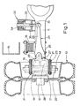
- a live driving axle 11 has a hub 12 to which are attached for rotation twin road wheels 13 and a brake disc 14.
- the axle 11 supports part of the weight carried by the vehicle chassis 15 through a multi-leaf spring 16 bolted to the axle in a conventional manner. This also helps locate the axle against rotation.
- a disc brake caliper 17 straddles both the disc 14 and a pair of brake pads 18 and 19, the caliper 17 being slidably mounted for movement parallel to the axis of the axle 11 by pins 21 which are a sliding fit in a support bracket 22 fixed to the axle casing.
- the pins 21 are supported in resilient bushes 23 in the caliper.
- a lever 24 is pivotally mounted on the caliper 17 and has one arm 25 extending parallel to the axle and another arm 26 having means (in the form of a rounded tappet face) for applying load to the pad 19 which is on the adjacent side of the disc 14.
- the arm 26 applies its load through a plunger 27 which is connected through an automatic adjuster of known type to a piston inside a cylinder 28 in the .caliper.
- the arm 25 is connected through a pushrod 31 to a spring actuator 32 mounted on the axle 11. Normally the piston 33 of the spring actuator holds a spring 34 compressed by means of air supplied to port 35.. When air is released from port 35, the spring applies a thrust to the pushrod 31 through the piston 33. The lever 24 then pivots so that pad 19 is applied by the plunger 27, pad 18 being applied by the reaction force of the lever 24 on the caliper 17.
- the resilient bushes 23 allow a limited tilting of the caliper 17 about an axis perpendicular to the axis of the axle 11. By this means, a large proportion of the reaction to the twisting moment applied to the caliper by the lever 24 is taken by the pads 18 and 19 and the disc 14, the centres of pressure of the pads being offset. Any drag load of the pads is taken by the support bracket 22 in the usual way.
- the lever 25 By extending parallel to the axle 11, the lever 25 creates no great installation problem, since it can easily avoid the leaf spring 16.
- the actuator 32 can also be installed well away from the spring 16 and its weight is supported by the axle.
- the pushrod 31 has sufficient articulation to allow for pad wear which will cause lateral shifting of the lever 24.
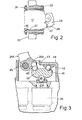
- Fig. 2 there is shown further additional means other than the guide pins for reacting the twisting moment applied to the caliper by the lever.
- the lever 24 is used to apply the brakes for parking or extreme emergency purposes and the caliper 17 deflects on the fixed support bracket 22 under the twisting moment applied by the lever, the clearance between two diagonally opposite adjacent pairs of faces 36 and 37 is closed so that the disc is spared from taking an excessive twisting load.
- the other diagonally opposite adjacent pairs of faces are provided so as to avoid making components peculiar to a particular side of the vehicle.
- Fig. 3 shows an auxiliary lever mechanism which achieves this.
- the plunger 27A has a recess for a ball 38 which sits in a similar recess in an auxiliary lever 39.
- a fulcrum is provided by another ball 41 which bears against a pivot block 42. This is free to slide on a flat surface 43 provided by a pivot housing 44 which also supports a pivot pin 45 for the main lever 24A.
- the load from lever arm 26A is transmitted through a thrust member or dolly 46 having part-spherical ends. The arrangement is such that the pad load is the sum of the lever load and the fulcrum load.
- the auxiliary lever mechanism has a ratio of 2:1.
- the auxiliary lever pivots are arranged such that lines intersecting the pivots form a triangle with angles substantially equal.
- limited tilting of the caliper may be provided for by rubber bushes in the fixed support bracket.
- the fixed support bracket may be combined with an actuator support bracket for mounting on the axle if the installation allows or requires a shorter lever arm.
- the axle mounted spring actuator may be replaced by an actuator mounted on the vehicle chassis, being a spring actuator or other power operated device or a conventional handbrake mechanism.
- Fig. 4 which is a plan view rather than an elevation as seen in Fig. 1. All parts are the same as those in Fig. 1 and carry the same references except the actuator 32A which is now a pull type having an output rod 31A connected to the lever arm 25 by a pull rod 31B.
- the actuator 32A is mounted on a chassis cross-member 15A.
- the caliper 17 and fixed support are rotated 90 0 compared with Fig. 1.
Landscapes
- Engineering & Computer Science (AREA)
- General Engineering & Computer Science (AREA)
- Mechanical Engineering (AREA)
- Transportation (AREA)
- Physics & Mathematics (AREA)
- Electromagnetism (AREA)
- Braking Arrangements (AREA)
Applications Claiming Priority (2)
| Application Number | Priority Date | Filing Date | Title |
|---|---|---|---|
| GB8201182 | 1982-01-12 | ||
| GB8201182 | 1982-01-12 |
Publications (2)
| Publication Number | Publication Date |
|---|---|
| EP0085252A1 true EP0085252A1 (fr) | 1983-08-10 |
| EP0085252B1 EP0085252B1 (fr) | 1986-04-16 |
Family
ID=10527656
Family Applications (1)
| Application Number | Title | Priority Date | Filing Date |
|---|---|---|---|
| EP82306870A Expired EP0085252B1 (fr) | 1982-01-12 | 1982-12-22 | Dispositif d'un frein à disque et d'un essieu de véhicule et arrangement d'un étrier de frein à disque |
Country Status (6)
| Country | Link |
|---|---|
| EP (1) | EP0085252B1 (fr) |
| JP (1) | JPS58134240A (fr) |
| BR (1) | BR8300106A (fr) |
| DE (1) | DE3270692D1 (fr) |
| ES (1) | ES8404651A1 (fr) |
| GB (1) | GB2113326A (fr) |
Families Citing this family (2)
| Publication number | Priority date | Publication date | Assignee | Title |
|---|---|---|---|---|
| DE3505773A1 (de) * | 1985-02-20 | 1986-08-21 | Alfred Teves Gmbh, 6000 Frankfurt | Teilbelag-scheibenbremse, insbesondere fuer kraftfahrzeuge |
| DE10219148C1 (de) * | 2002-04-29 | 2003-09-18 | Wabco Perrot Bremsen Gmbh | Linearzuspannvorrichtung für eine Scheibenbremse |
Citations (6)
| Publication number | Priority date | Publication date | Assignee | Title |
|---|---|---|---|---|
| US3548974A (en) * | 1968-11-06 | 1970-12-22 | Hermann Klaue | Lever actuated disc brake |
| GB1256713A (fr) * | 1968-04-11 | 1971-12-15 | ||
| US3980159A (en) * | 1974-12-19 | 1976-09-14 | Mechanics, Inc. | Cam actuated disc brake assembly |
| DE2522255B2 (de) * | 1974-05-20 | 1979-01-18 | Girling Ltd., Birmingham, West Midlands (Grossbritannien) | Befestigungseinrichtung zum Abstützen eines Satteljoches einer Scheibenbremse an einem fahrzeugfesten Bauteil, insbesondere an einem Schienenfahrzeug- oder Drehgestellrahmen |
| DE2934608A1 (de) * | 1978-08-28 | 1980-03-20 | Bendix Corp | Scheibenbremse |
| EP0041450A1 (fr) * | 1980-06-02 | 1981-12-09 | The Bendix Corporation | Frein à disque |
Family Cites Families (1)
| Publication number | Priority date | Publication date | Assignee | Title |
|---|---|---|---|---|
| GB1355960A (en) * | 1971-03-08 | 1974-06-12 | Automotive Prod Co Ltd | Disc brakes |
-
1982
- 1982-12-22 GB GB08236494A patent/GB2113326A/en not_active Withdrawn
- 1982-12-22 EP EP82306870A patent/EP0085252B1/fr not_active Expired
- 1982-12-22 DE DE8282306870T patent/DE3270692D1/de not_active Expired
-
1983
- 1983-01-11 BR BR8300106A patent/BR8300106A/pt unknown
- 1983-01-11 JP JP58001806A patent/JPS58134240A/ja active Pending
- 1983-01-12 ES ES518937A patent/ES8404651A1/es not_active Expired
Patent Citations (6)
| Publication number | Priority date | Publication date | Assignee | Title |
|---|---|---|---|---|
| GB1256713A (fr) * | 1968-04-11 | 1971-12-15 | ||
| US3548974A (en) * | 1968-11-06 | 1970-12-22 | Hermann Klaue | Lever actuated disc brake |
| DE2522255B2 (de) * | 1974-05-20 | 1979-01-18 | Girling Ltd., Birmingham, West Midlands (Grossbritannien) | Befestigungseinrichtung zum Abstützen eines Satteljoches einer Scheibenbremse an einem fahrzeugfesten Bauteil, insbesondere an einem Schienenfahrzeug- oder Drehgestellrahmen |
| US3980159A (en) * | 1974-12-19 | 1976-09-14 | Mechanics, Inc. | Cam actuated disc brake assembly |
| DE2934608A1 (de) * | 1978-08-28 | 1980-03-20 | Bendix Corp | Scheibenbremse |
| EP0041450A1 (fr) * | 1980-06-02 | 1981-12-09 | The Bendix Corporation | Frein à disque |
Also Published As
| Publication number | Publication date |
|---|---|
| ES518937A0 (es) | 1984-05-01 |
| GB2113326A (en) | 1983-08-03 |
| ES8404651A1 (es) | 1984-05-01 |
| BR8300106A (pt) | 1983-10-04 |
| JPS58134240A (ja) | 1983-08-10 |
| EP0085252B1 (fr) | 1986-04-16 |
| DE3270692D1 (en) | 1986-05-22 |
Similar Documents
| Publication | Publication Date | Title |
|---|---|---|
| US5069312A (en) | Handbrake for single-cylinder truck-mounted railway car brake | |
| US3134459A (en) | Caliper type spot brake | |
| CN113167344B (zh) | 提供对活塞施加到至少一个制动片上的推力的平衡分布的盘式制动器 | |
| EP0046619B1 (fr) | Installation de frein à disque pour véhicules ferroviaires | |
| US3780837A (en) | Single cylinder truck-mounted brake | |
| US4312428A (en) | Truck mounted brake apparatus | |
| US5785159A (en) | Braking mechanism for railroad cars having both pneumatic and mechanical actuators | |
| CA2442787C (fr) | Dispositif ameliore de jonction de levier de frein a main pour frein de vehicule ferroviaire monte sur bogie monocylindre | |
| JPS63140131A (ja) | ディスクブレーキ | |
| EP0085252B1 (fr) | Dispositif d'un frein à disque et d'un essieu de véhicule et arrangement d'un étrier de frein à disque | |
| CA2337200A1 (fr) | Frein de bogie | |
| US3604538A (en) | Railway vehicle brakes | |
| US4039051A (en) | Disc brake construction, especially for rail vehicles | |
| US3062328A (en) | Railway wheel, brake and suspension assemblies | |
| US4420065A (en) | Railway brakes | |
| USRE25817E (en) | Spot type disc brakes for vehicles | |
| CN101103209A (zh) | 机械盘式制动组件 | |
| US3624765A (en) | Disc brake | |
| US2820529A (en) | Hand brake linkage | |
| US3092211A (en) | Railway disk brakes | |
| US3327816A (en) | Braking systems for vehicles | |
| RU1838168C (ru) | Комбинированный тормозной узел сменной ходовой тележки железнодорожного транспортного средства | |
| JP6660216B2 (ja) | ブレーキ支持部材及びこれを備えるブレーキ装置 | |
| EP1535817B1 (fr) | Interface de levier de frein à main perfectionné pour un système de freinage ferroviaire monocylindrique monté sur wagon | |
| EP0879751A1 (fr) | Bogie amelioré pour véhicules ferroviaires |
Legal Events
| Date | Code | Title | Description |
|---|---|---|---|
| PUAI | Public reference made under article 153(3) epc to a published international application that has entered the european phase |
Free format text: ORIGINAL CODE: 0009012 |
|
| AK | Designated contracting states |
Designated state(s): BE DE FR GB IT SE |
|
| 17P | Request for examination filed |
Effective date: 19831017 |
|
| RBV | Designated contracting states (corrected) |
Designated state(s): DE FR GB IT |
|
| GRAA | (expected) grant |
Free format text: ORIGINAL CODE: 0009210 |
|
| AK | Designated contracting states |
Kind code of ref document: B1 Designated state(s): DE FR GB IT |
|
| ITF | It: translation for a ep patent filed | ||
| REF | Corresponds to: |
Ref document number: 3270692 Country of ref document: DE Date of ref document: 19860522 |
|
| ET | Fr: translation filed | ||
| PLBE | No opposition filed within time limit |
Free format text: ORIGINAL CODE: 0009261 |
|
| STAA | Information on the status of an ep patent application or granted ep patent |
Free format text: STATUS: NO OPPOSITION FILED WITHIN TIME LIMIT |
|
| 26N | No opposition filed | ||
| GBPC | Gb: european patent ceased through non-payment of renewal fee | ||
| PG25 | Lapsed in a contracting state [announced via postgrant information from national office to epo] |
Ref country code: DE Effective date: 19880901 |
|
| PG25 | Lapsed in a contracting state [announced via postgrant information from national office to epo] |
Ref country code: GB Free format text: LAPSE BECAUSE OF NON-PAYMENT OF DUE FEES Effective date: 19881122 |
|
| PGFP | Annual fee paid to national office [announced via postgrant information from national office to epo] |
Ref country code: FR Payment date: 19891108 Year of fee payment: 8 |
|
| PG25 | Lapsed in a contracting state [announced via postgrant information from national office to epo] |
Ref country code: FR Effective date: 19910830 |
|
| REG | Reference to a national code |
Ref country code: FR Ref legal event code: ST |