EP0085285B1 - Kompressor-Antriebssystem - Google Patents
Kompressor-Antriebssystem Download PDFInfo
- Publication number
- EP0085285B1 EP0085285B1 EP19820850247 EP82850247A EP0085285B1 EP 0085285 B1 EP0085285 B1 EP 0085285B1 EP 19820850247 EP19820850247 EP 19820850247 EP 82850247 A EP82850247 A EP 82850247A EP 0085285 B1 EP0085285 B1 EP 0085285B1
- Authority
- EP
- European Patent Office
- Prior art keywords
- motor
- pressure
- compressor
- frequency
- gas
- Prior art date
- Legal status (The legal status is an assumption and is not a legal conclusion. Google has not performed a legal analysis and makes no representation as to the accuracy of the status listed.)
- Expired
Links
Images


Classifications
-
- H—ELECTRICITY
- H02—GENERATION; CONVERSION OR DISTRIBUTION OF ELECTRIC POWER
- H02P—CONTROL OR REGULATION OF ELECTRIC MOTORS, ELECTRIC GENERATORS OR DYNAMO-ELECTRIC CONVERTERS; CONTROLLING TRANSFORMERS, REACTORS OR CHOKE COILS
- H02P27/00—Arrangements or methods for the control of AC motors characterised by the kind of supply voltage
- H02P27/04—Arrangements or methods for the control of AC motors characterised by the kind of supply voltage using variable-frequency supply voltage, e.g. inverter or converter supply voltage
- H02P27/06—Arrangements or methods for the control of AC motors characterised by the kind of supply voltage using variable-frequency supply voltage, e.g. inverter or converter supply voltage using DC to AC converters or inverters
- H02P27/08—Arrangements or methods for the control of AC motors characterised by the kind of supply voltage using variable-frequency supply voltage, e.g. inverter or converter supply voltage using DC to AC converters or inverters with pulse width modulation
-
- F—MECHANICAL ENGINEERING; LIGHTING; HEATING; WEAPONS; BLASTING
- F04—POSITIVE - DISPLACEMENT MACHINES FOR LIQUIDS; PUMPS FOR LIQUIDS OR ELASTIC FLUIDS
- F04C—ROTARY-PISTON, OR OSCILLATING-PISTON, POSITIVE-DISPLACEMENT MACHINES FOR LIQUIDS; ROTARY-PISTON, OR OSCILLATING-PISTON, POSITIVE-DISPLACEMENT PUMPS
- F04C28/00—Control of, monitoring of, or safety arrangements for, pumps or pumping installations specially adapted for elastic fluids
- F04C28/08—Control of, monitoring of, or safety arrangements for, pumps or pumping installations specially adapted for elastic fluids characterised by varying the rotational speed
-
- F—MECHANICAL ENGINEERING; LIGHTING; HEATING; WEAPONS; BLASTING
- F04—POSITIVE - DISPLACEMENT MACHINES FOR LIQUIDS; PUMPS FOR LIQUIDS OR ELASTIC FLUIDS
- F04C—ROTARY-PISTON, OR OSCILLATING-PISTON, POSITIVE-DISPLACEMENT MACHINES FOR LIQUIDS; ROTARY-PISTON, OR OSCILLATING-PISTON, POSITIVE-DISPLACEMENT PUMPS
- F04C28/00—Control of, monitoring of, or safety arrangements for, pumps or pumping installations specially adapted for elastic fluids
- F04C28/28—Safety arrangements; Monitoring
-
- G—PHYSICS
- G05—CONTROLLING; REGULATING
- G05D—SYSTEMS FOR CONTROLLING OR REGULATING NON-ELECTRIC VARIABLES
- G05D16/00—Control of fluid pressure
- G05D16/20—Control of fluid pressure characterised by the use of electric means
- G05D16/2006—Control of fluid pressure characterised by the use of electric means with direct action of electric energy on controlling means
- G05D16/2066—Control of fluid pressure characterised by the use of electric means with direct action of electric energy on controlling means using controlling means acting on the pressure source
-
- G—PHYSICS
- G05—CONTROLLING; REGULATING
- G05D—SYSTEMS FOR CONTROLLING OR REGULATING NON-ELECTRIC VARIABLES
- G05D16/00—Control of fluid pressure
- G05D16/20—Control of fluid pressure characterised by the use of electric means
- G05D16/2006—Control of fluid pressure characterised by the use of electric means with direct action of electric energy on controlling means
- G05D16/208—Control of fluid pressure characterised by the use of electric means with direct action of electric energy on controlling means using a combination of controlling means as defined in G05D16/2013 and G05D16/2066
-
- F—MECHANICAL ENGINEERING; LIGHTING; HEATING; WEAPONS; BLASTING
- F04—POSITIVE - DISPLACEMENT MACHINES FOR LIQUIDS; PUMPS FOR LIQUIDS OR ELASTIC FLUIDS
- F04C—ROTARY-PISTON, OR OSCILLATING-PISTON, POSITIVE-DISPLACEMENT MACHINES FOR LIQUIDS; ROTARY-PISTON, OR OSCILLATING-PISTON, POSITIVE-DISPLACEMENT PUMPS
- F04C18/00—Rotary-piston pumps specially adapted for elastic fluids
- F04C18/08—Rotary-piston pumps specially adapted for elastic fluids of intermeshing-engagement type, i.e. with engagement of co-operating members similar to that of toothed gearing
- F04C18/12—Rotary-piston pumps specially adapted for elastic fluids of intermeshing-engagement type, i.e. with engagement of co-operating members similar to that of toothed gearing of other than internal-axis type
- F04C18/14—Rotary-piston pumps specially adapted for elastic fluids of intermeshing-engagement type, i.e. with engagement of co-operating members similar to that of toothed gearing of other than internal-axis type with toothed rotary pistons
- F04C18/16—Rotary-piston pumps specially adapted for elastic fluids of intermeshing-engagement type, i.e. with engagement of co-operating members similar to that of toothed gearing of other than internal-axis type with toothed rotary pistons with helical teeth, e.g. chevron-shaped, screw type
-
- H—ELECTRICITY
- H02—GENERATION; CONVERSION OR DISTRIBUTION OF ELECTRIC POWER
- H02P—CONTROL OR REGULATION OF ELECTRIC MOTORS, ELECTRIC GENERATORS OR DYNAMO-ELECTRIC CONVERTERS; CONTROLLING TRANSFORMERS, REACTORS OR CHOKE COILS
- H02P27/00—Arrangements or methods for the control of AC motors characterised by the kind of supply voltage
- H02P27/04—Arrangements or methods for the control of AC motors characterised by the kind of supply voltage using variable-frequency supply voltage, e.g. inverter or converter supply voltage
- H02P27/047—V/F converter, wherein the voltage is controlled proportionally with the frequency
Definitions
- the present invention relates to a compressor drive system for controlling the gas pressure in a volume of pressurised gas connected to the compressor in which the compressor is driven by a brushless alternating current motor, in the following also called ac-motor.
- the present invention aims at creating a compressor direct drive system including a brushless alternating current motor in which the pressure in a volume of pressurised gas connected to the compressor is controlled by controlling the speed of the ac-motor, whereby the motor current is controlled such that the normal speed maximum load current never is exceeded during the motor starts, thus allowing frequent motor starts without overheating the motor.
- the drive system is provided with means for sensing a preset maximum value of the delivered gas pressure and for decreasing the amplitude and frequency of the voltage supplied to the ac-motor to zero, when the preset maximum pressure is exceeded, in order to stop the motor.
- a container with relief valve on the downstream side of the compressor in order to depressurize the container when the motor is stopped. This makes it possible to restart the motor without any back pressure on the compressor.
- the compressor can be driven directly by the ac-motor at optimum speed without the use of a gearbox or other device normally required to change the motor speed into the optimum compressor speed. Since such devices are costly, introduce power losses, are subject to wear and may generate noise, it is possible to make a compressor plant cheaper, save energy and improve the reliability of the system by the present invention.
- the possibility to operate the ac-motor at higher speeds than those obtainable at network frequency makes it possible to reduce the motor size for a given power.
- the reason is that the size of ac-motors is proportional to the driving torque, which is inversely proportional to the motor speed at a given output power.
- a frequency converter can supply a voltage of virtually any frequency it is possible to choose the number of poles of the ac-motor in order to decrease the costs for the motor. It is known that a four-pole motor has a better relation between active and inactive material than a two-pole motor. The four-pole motor is, therefore, cheaper for a given rated torque.
- the motor can be accelerated with a current which is not greater than the normal speed full load current.
- compressor capacity is regulated by speed control normal capacity regulating devices, such as inlet throttles on rotary compressors or inlet valve lifters on piston compressors, may be omitted.
- fig. 1 shows a compressor plant with drive system according to the invention.
- Fig. 2 shows the power circuits for the driving of the brushless alternating current motor.
- Fig. 3 shows the controller of fig. 2.
- Fig. 4 shows a regulator of the fig. 3 controller.
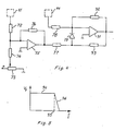
- Fig. 5 shows a transfer function of the regulator of fig. 4.
- the compressor plant shown in fig. 1 comprises a compressor 101 which by means of a shaft 102 is directly coupled to a brushless alternating current motor 23, whereby the compressor is driven with the same speed as the motor.
- the compressor shown in the drawing is of the oil- injected type, preferably a screw compressor, but could be of any type, e.g. a piston compressor.
- shaft 102 is, or is coupled to, the shaft of one of the screws.
- the shaft is the crank shaft.
- Gas to be compressed enters compressor 101 via intake filter 113.
- the compressed gas delivered by compressor 101 is conducted via check valve 103 to oil separator 104 where the oil is separated from the gas and collected on the bottom.
- the oil is then returned via oil cooler 110, oil filter 111 and oil stop valve 112 to the injection gallery of compressor 101.
- the compressed gas is conducted via check valve 105 to a pressure gas volume 106, which normally is the conduit system leading to the consumers.
- the plant is further provided with a safety valve 107 and a relief valve 108.
- the relief valve is controlled by the pressure at the outlet of compressor 101 such that it takes the position shown in the drawing when that pressure falls below a certain level upon stopping of motor 23.
- Container 104 is then depressurized so that a subsequent motor start can be performed without any counter pressure at the outlet of compressor 101.
- the shown motor 23 is a three-phase brushless alternating current motor, e.g. an asynchronous motor.
- the motor is supplied with power from a converter 114 connected to a three-phase network.
- the converter comprises a three-phase rectifier, a direct current link, an inverter with six switching elements 31-36 and a controller 10 as shown in fig. 2.
- the controller is provided with an input 19 for a continuously variable speed controlling signal and an input 20 for a start/stop signal.
- the shown compressor plant comprises pressure sensing means 109 which delivers a voltage being proportional to the pressure in pressure gas volume 106. This voltage, which is negative, is applied via resistor 120 to one of the inputs of operational amplifier 118.
- a reference voltage corresponding to the desired maximum pressure in volume 106 is set on potentiometer 116 and applied via resistor 117 to the input of amplifier 118.
- the closed loop amplification of amplifier fisis set on the variable resistor 119 and corresponds to the desired difference between maximum pressure and minimum pressure in volume 106. If the inverting input of amplifier 118 is used the voltage supplied to input 19 will change from zero volt, corresponding to minimum motor speed, to a predetermined negative value, corresponding to maximum motor speed, when the pressure in volume 106 changes from maximum pressure to minimum pressure.
- the output voltage of amplifier 118 is also applied to a means for sensing a preset maximum pressure in form of a comparator 115.
- the drive system shown in fig. 2 comprises a threephase rectifier 22 which is connected to a standard fixed frequency mains supply.
- the rectifier delivers direct current of substantially constant voltage to conduits 24, 25, which constitute a positive 24 and a negative 25 terminal of a direct current supply for an inverter.
- the inverter comprises six switching elements 31-36 for successively connecting motor terminals 28, 29, 30 on a brushless alternating current motor 23 to. the positive terminal 24 and the negative terminal 25 of the direct current supply.
- the switching elements are in the drawing shown as transistors but could, of course, be combinations of thyristors or other elements.
- a diode 27 is placed in anti-parallel over each transistor to take care of reactive currents at the switching off of the transistor.
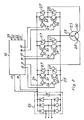
- control signals are supplied from outputs 11-16 on a controller 10 as shown in fig. 3. These control signals are supplied via amplifiers 26 to the base of respective transistor. Controller 10 is provided with inputs 17, 18 through which the direct current in conduit 24 is sensed. Controller 10 is further provided with an output 39 and inputs 19, 20, 21. Output 39 is only used if it during operation is desired to change the direction of rotation of the motor. The direction of rotation is selected by applying a logical signal to input 21. If rotation in only one direction is desired input 21 is connected either to a positive voltage or common. The speed of. motor 23 may be changed by variation of a voltage applied to input 19. If, as for instance in a grinding machine, it is desired to drive the motor at a certain speed, input 19 is connected to a suitable voltage corresponding to the desired speed. Input 20 is intended for receiving a start/stop signal by which rotation or no rotation is chosen.
- Controller 10 which is shown more in detail in fig. 3, comprises a sensing means 40 for sensing the direct current in conduit 24. This current is presented as a voltage between inputs 17 and 18.
- the output signal of sensing means 40 is applied to a first peak detector 41, a low-pass filter 42, a second peak detector 43 and a comparator 49.
- Peak detectors 41 and 43 comprise diodes to react on positive and negative signals respectively.
- the peak detectors also comprise low-pass filters.
- First peak detector 41 preferably has a time constant of about 4/f where f is the maximum fundamental frequency of the current supplied to motor 23.
- the cut-off frequency, -3dB, of peak detector 41 is preferably about 0.1 f.
- Lowpass filter 42 preferably has about the same cut-off frequency.
- Second peak detector 43 preferably has a time constant of about 1/f and a cut-off frequency of about 0.5 f.
- the peak value signal from peak detector 41 is supplied to a first regulator 45, which is shown more in detail in fig. 4.
- Input signals from inputs 19 and 20 are supplied to a means 44 in form of a ramp generator.
- Ramp generator 44 comprises one or two operational amplifiers connected as integrators to supply regulator 45 with an increasing ramp voltage at motor start acceleration and a decreasing ramp voltage at motor stop deceleration. In this way it is possible to avoid that the normal speed maximum load current is exceeded when the motor is started or stopped.
- a change in the speed demand signal at input 19 is also integrated by ramp generator 44. Thus it takes some time before the output of ramp generator 44 becomes fully adapted to the input signals.
- the peak value signal from first peak detector 41 is applied to one of the inputs of operational amplifier 75 via resistor 72. This signal is compared with a reference signal preset on variable resistor 73 and fed to the amplifier via resistor 74.
- the amplifier is provided with a feed-back resistor 76.
- the output signal of amplifier 75 is via a resistor 77 applied to diode 79.
- the output signal from ramp generator 44 is via resistor 78 supplied to one of the inputs of operational amplifier 91.
- Amplifier 91 is provided with a first feed-back resistor 92 and a second feed-back resistor 93 in series with diode 79. Resistor 93 has a much lower resistance than resistor 92. Preferably the ratio is about 1/20.
- the frequency controlling signal from the output of amplifier 91 is delivered to a voltage-controlled oscillator 47, output 39 and an analog divider 46, e.g. Analog Devices AD 534.
- the voltage-controlled oscillator produces an output signal whose frequency is proportional to the input voltage.
- the rectified mean value signal obtained from low-pass filter 42 corresponds to the power supplied to motor 23 because the voltage of the direct current supply 24, 25 is substantially constant.
- This signal is supplied to divider 46 where it is divided with the frequency controlling signal, which is the demand signal for rotational speed of motor 23.
- the output signal of divider 46 will thus correspond to the torque demand from motor 23.
- This output signal, first voltage controlling signal is supplied to a second regulator 48.
- the negative peak value signal, second voltage controlling signal, obtained from second peak detector 43 is also supplied to regulator 48 so that the output signal of regulator 48 becomes proportional to the difference between the first and the second voltage controlling signals.
- the negative peak value signal from peak detector 43 corresponds to the degree of magnetization of motor 23.
- This signal is obtained from negative pulses which are fed back to the direct current source when the transistors 31-36 are switched off.
- By controlling the level of these negative pulses it is possible to obtain a predetermined level of magnetization of the motor allowing both a high power to weight ratio and the avoiding of oversaturation, which would give unacceptable losses.
- the output signal from voltage-controlled oscillator 47 is supplied to a timer 51, preferably an industrial timer of standard type 555, and to a divider 50.
- Divider 50 is preferably a programmable counter which delivers a pulse train having a frequency which is equal to the frequency of the input signal divided by a chosen constant.
- Timer 51 delivers a pulse train whose frequency is equal to the frequency of the output signal from voltage-controlled oscillator 47.
- the pulse width is controlled by the output signal from second regulator 48.
- This pulse train is supplied to AND gates 81, 83 and 85.
- the pulse train from divider 50 is supplied as clock signal to ring counter 52. In the ring counter a 1 and five 0's are stored.
- the 1 is shifted around by the pulse train from output 53 through 58 and back to 53. This makes one period of the fundamental frequency of the current supplied to motor 23.
- Outputs 53-58 of ring counter 52 are decoded by OR gates 59, 60 and 61. The output of each of these gates is high half the time and low half the time.
- a logic signal inverter 62 and NAND gates 63-68 are provided for selecting direction of rotation of motor 23.
- the output signals of gates 59,60 and 61 are supplied to AND gates 81-86 for controlling the actuation of switching transistors 31-36 in the inverter.
- the inputs of gates 82, 84 and 86 are provided with logic signal inverters 71, 70 and 69 respectively.
- the mean value over half a period of the fundamental frequency of the voltage applied to any of the motor terminals will change simultaneously with the frequency as required by basic electromagnetic laws. Additional control of the mean value voltage is obtained by variation of the pulse width, which is controlled by regulator 48.
Landscapes
- Engineering & Computer Science (AREA)
- Physics & Mathematics (AREA)
- Automation & Control Theory (AREA)
- General Engineering & Computer Science (AREA)
- Fluid Mechanics (AREA)
- General Physics & Mathematics (AREA)
- Mechanical Engineering (AREA)
- Power Engineering (AREA)
- Control Of Motors That Do Not Use Commutators (AREA)
- Medicines Containing Material From Animals Or Micro-Organisms (AREA)
- Jellies, Jams, And Syrups (AREA)
- Control Of Linear Motors (AREA)
- Control Of Positive-Displacement Pumps (AREA)
- Transition And Organic Metals Composition Catalysts For Addition Polymerization (AREA)
Claims (3)
Priority Applications (1)
| Application Number | Priority Date | Filing Date | Title |
|---|---|---|---|
| AT82850247T ATE21600T1 (de) | 1981-12-18 | 1982-12-01 | Kompressor-antriebssystem. |
Applications Claiming Priority (2)
| Application Number | Priority Date | Filing Date | Title |
|---|---|---|---|
| CH8098/81A CH660100A5 (fr) | 1981-12-18 | 1981-12-18 | Dispositif d'entrainement d'un compresseur. |
| CH8098/81 | 1981-12-18 |
Publications (2)
| Publication Number | Publication Date |
|---|---|
| EP0085285A1 EP0085285A1 (de) | 1983-08-10 |
| EP0085285B1 true EP0085285B1 (de) | 1986-08-20 |
Family
ID=4335128
Family Applications (1)
| Application Number | Title | Priority Date | Filing Date |
|---|---|---|---|
| EP19820850247 Expired EP0085285B1 (de) | 1981-12-18 | 1982-12-01 | Kompressor-Antriebssystem |
Country Status (10)
| Country | Link |
|---|---|
| US (1) | US4492526A (de) |
| EP (1) | EP0085285B1 (de) |
| JP (1) | JPS58112490A (de) |
| AT (1) | ATE21600T1 (de) |
| BR (1) | BR8207210A (de) |
| CA (1) | CA1196074A (de) |
| CH (1) | CH660100A5 (de) |
| DE (1) | DE3272771D1 (de) |
| FI (1) | FI80171C (de) |
| MX (1) | MX158240A (de) |
Cited By (1)
| Publication number | Priority date | Publication date | Assignee | Title |
|---|---|---|---|---|
| DE10047940A1 (de) * | 2000-06-02 | 2001-12-13 | Hitachi Ltd | Schraubenkompressionsvorrichtung und Verfahren zu deren Betriebssteuerung |
Families Citing this family (27)
| Publication number | Priority date | Publication date | Assignee | Title |
|---|---|---|---|---|
| CH648507A5 (fr) * | 1982-09-22 | 1985-03-29 | Cerac Inst Sa | Machine frappeuse electrique. |
| JPH0631627B2 (ja) * | 1984-07-25 | 1994-04-27 | 株式会社日立製作所 | 回転容積形真空ポンプ装置 |
| EP0209499A3 (de) * | 1985-06-10 | 1987-08-12 | Institut Cerac S.A. | Kompressoranlage |
| US4627243A (en) * | 1985-09-26 | 1986-12-09 | Union Carbide Corporation | Gas supply system for variable demand application |
| JPS6338693A (ja) * | 1986-07-31 | 1988-02-19 | Nippon Air Brake Co Ltd | 鉄道車両用調圧方法 |
| FR2633072B1 (fr) * | 1988-06-21 | 1990-11-02 | Renault | Circuit de commande, de regulation et de controle d'un debit de fluide |
| US5253982A (en) * | 1992-11-23 | 1993-10-19 | Vickers, Incorporated | Electrohydraulic pump load control system |
| DE19517748A1 (de) * | 1994-05-16 | 1995-11-23 | Toyoda Automatic Loom Works | Verfahren und Vorrichtung zur Zuführung von Druckluft |
| EP0704784A1 (de) * | 1994-09-30 | 1996-04-03 | F.I.A.C. S.r.l. | Verfahren und Vorrichtung zur Erzeugung und zur Zuführ komprimierter Luft |
| DE9419651U1 (de) * | 1994-12-08 | 1995-02-02 | Hatlapa Uetersener Maschinenfabrik GmbH & Co, 25436 Uetersen | Kompressoranlage |
| JP5222900B2 (ja) * | 1996-02-19 | 2013-06-26 | 株式会社日立産機システム | スクリュー圧縮機の運転方法 |
| KR0176909B1 (ko) * | 1996-05-08 | 1999-10-01 | 구자홍 | 선형 압축기 구동장치 |
| DE19628585C2 (de) * | 1996-07-16 | 2001-12-20 | Danfoss As | Verfahren zum Kommutieren eines bürstenlosen Motors und Speiseschaltung für einen bürstenlosen Motor |
| BE1012655A3 (nl) * | 1998-12-22 | 2001-02-06 | Atlas Copco Airpower Nv | Werkwijze voor het besturen van een compressorinstallatie en aldus bestuurde compressorinstallatie. |
| US6484522B2 (en) * | 2000-06-23 | 2002-11-26 | Kobe Steel, Ltd. | Screw compressor for refrigerating apparatus |
| BE1013828A3 (nl) * | 2000-11-08 | 2002-09-03 | Atlas Copco Airpower Nv | Werkwijze voor het regelen van een compressorinstallatie met een droger en daarbij gebruikte compressorinstallatie. |
| SG161736A1 (en) * | 2002-02-25 | 2010-06-29 | Daikin Ind Ltd | Motor control method and its apparatus |
| DE102004007882B4 (de) * | 2003-03-31 | 2009-12-10 | Hitachi Koki Co., Ltd. | Luftkompressor und Verfahren zu seinem Steuern |
| JP4069450B2 (ja) * | 2003-06-24 | 2008-04-02 | 日立工機株式会社 | 空気圧縮機及びその制御方法 |
| SE524343C2 (sv) * | 2003-10-17 | 2004-07-27 | Svenska Rotor Maskiner Ab | Varvtalsreglerad skruvrotorkompressor |
| US7096681B2 (en) * | 2004-02-27 | 2006-08-29 | York International Corporation | System and method for variable speed operation of a screw compressor |
| TWI257761B (en) * | 2005-01-27 | 2006-07-01 | Delta Electronics Inc | Driving apparatus for brushless DC motor without hall sensor |
| JP2012525899A (ja) * | 2009-05-08 | 2012-10-25 | コーニンクレッカ フィリップス エレクトロニクス エヌ ヴィ | モータで補助され手動で制御される運動アセンブリ、それを有するx線装置、方法および使用 |
| US10941770B2 (en) | 2010-07-20 | 2021-03-09 | Trane International Inc. | Variable capacity screw compressor and method |
| DE102016011437A1 (de) * | 2016-09-21 | 2018-03-22 | Knorr-Bremse Systeme für Nutzfahrzeuge GmbH | Schraubenkompressorsystem für ein Nutzfahrzeug |
| TW201826689A (zh) | 2016-10-05 | 2018-07-16 | 美商江森自控科技公司 | 用於暖氣、通風、空調及冷凍系統之變速驅動器 |
| DE102022207777A1 (de) | 2022-07-28 | 2024-02-08 | Siemens Energy Global GmbH & Co. KG | Verfahren zum Betreiben einer Elektrolyseanlage sowie Elektrolyseanlage |
Family Cites Families (15)
| Publication number | Priority date | Publication date | Assignee | Title |
|---|---|---|---|---|
| US2687841A (en) * | 1947-12-29 | 1954-08-31 | Nellie Churchman | Valve used as a control |
| US2629537A (en) * | 1950-08-19 | 1953-02-24 | Westinghouse Electric Corp | Compressor motor control system |
| DE1588283A1 (de) * | 1967-05-06 | 1970-05-14 | Hanning Elektro Werke | Durch einen Elektromotor angetriebene Pumpe,insbesondere fuer Geschirrspuelmaschinen |
| US3499297A (en) * | 1969-02-20 | 1970-03-10 | John D Ruff | Variable capacity refrigeration system |
| JPS5724632B2 (de) * | 1973-07-28 | 1982-05-25 | ||
| US3860858A (en) * | 1973-12-19 | 1975-01-14 | Nasa | Variable frequency inverter for ac induction motors with torque, speed and braking control |
| DE2618440A1 (de) * | 1976-04-27 | 1977-11-10 | Sullair Europ Corp | Verfahren und vorrichtung zur steuerung des betriebs eines verdichters |
| HU179165B (en) * | 1976-12-06 | 1982-08-28 | Epitoegepgyarto Vallalat | Method and circuit array of controlling current convrters,preferably for continuous speed-control of a.c. motors |
| US4145161A (en) * | 1977-08-10 | 1979-03-20 | Standard Oil Company (Indiana) | Speed control |
| US4177649A (en) * | 1977-11-01 | 1979-12-11 | Borg-Warner Corporation | Surge suppression apparatus for compressor-driven system |
| ZA792500B (en) * | 1978-06-01 | 1980-09-24 | Lnc Ind Ltd | Control system for polyphase loads |
| US4259620A (en) * | 1978-10-18 | 1981-03-31 | Westinghouse Electric Corp. | Low cost, variable speed, constant torque induction motor drive |
| US4220440A (en) * | 1979-04-06 | 1980-09-02 | Superior Electric Supply Co. | Automatic load seeking control for a pumpjack motor |
| JPS55164792A (en) * | 1979-06-11 | 1980-12-22 | Mayekawa Mfg Co Ltd | Driving mechanism for screw compressor |
| JPS56107991A (en) * | 1980-01-31 | 1981-08-27 | Nec Corp | Pneumatic pressure control system |
-
1981
- 1981-12-18 CH CH8098/81A patent/CH660100A5/fr not_active IP Right Cessation
-
1982
- 1982-11-26 US US06/444,827 patent/US4492526A/en not_active Expired - Lifetime
- 1982-12-01 AT AT82850247T patent/ATE21600T1/de not_active IP Right Cessation
- 1982-12-01 DE DE8282850247T patent/DE3272771D1/de not_active Expired
- 1982-12-01 EP EP19820850247 patent/EP0085285B1/de not_active Expired
- 1982-12-13 BR BR8207210A patent/BR8207210A/pt not_active IP Right Cessation
- 1982-12-14 CA CA000417666A patent/CA1196074A/en not_active Expired
- 1982-12-14 MX MX195613A patent/MX158240A/es unknown
- 1982-12-17 JP JP57220379A patent/JPS58112490A/ja active Pending
- 1982-12-17 FI FI824356A patent/FI80171C/fi not_active IP Right Cessation
Cited By (2)
| Publication number | Priority date | Publication date | Assignee | Title |
|---|---|---|---|---|
| DE10047940A1 (de) * | 2000-06-02 | 2001-12-13 | Hitachi Ltd | Schraubenkompressionsvorrichtung und Verfahren zu deren Betriebssteuerung |
| DE10047940B4 (de) * | 2000-06-02 | 2005-06-23 | Hitachi, Ltd. | Verfahren zur Regelung des Betriebs einer ölfreien Schraubenkompressionsvorrichtung |
Also Published As
| Publication number | Publication date |
|---|---|
| FI824356L (fi) | 1983-06-19 |
| JPS58112490A (ja) | 1983-07-04 |
| CH660100A5 (fr) | 1987-03-13 |
| US4492526A (en) | 1985-01-08 |
| BR8207210A (pt) | 1983-10-11 |
| FI824356A0 (fi) | 1982-12-17 |
| ATE21600T1 (de) | 1986-09-15 |
| DE3272771D1 (en) | 1986-09-25 |
| FI80171C (fi) | 1990-04-10 |
| FI80171B (fi) | 1989-12-29 |
| CA1196074A (en) | 1985-10-29 |
| MX158240A (es) | 1989-01-17 |
| EP0085285A1 (de) | 1983-08-10 |
Similar Documents
| Publication | Publication Date | Title |
|---|---|---|
| EP0085285B1 (de) | Kompressor-Antriebssystem | |
| US4489261A (en) | Method and means for feeding electric energy to a portable power tool | |
| EP0171094B1 (de) | Verfahren zum Antrieb des Laufrades einer Flüssigkeitspumpe | |
| EP0083326B1 (de) | Verfahren und Gerät zur Regelung eines bürstenlosen Wechselstrommotors | |
| US5969957A (en) | Single phase to three phase converter | |
| US4514991A (en) | Variable speed drive motor system with inverter control | |
| US4655688A (en) | Control for liquid ring vacuum pumps | |
| EP0833436A2 (de) | Wechselstrommotorregelung für Hochgeschwindigkeits-Tiefbrunnenpumpen | |
| US4601351A (en) | Electrically driven hammer machine | |
| US4689543A (en) | Frequency and voltage control for inverter powered AC motor | |
| EP0280876B1 (de) | System und Methode zur Optimierung der Erzeugung elektrischer Leistung | |
| JP3585728B2 (ja) | コンプレッサ制御装置 | |
| US6135720A (en) | Air compressors of sliding vane eccentric rotor type | |
| US4550282A (en) | Method and device for controlling a brushless alternating current motor | |
| US6053703A (en) | Control method for displacement-type fluid machine, and apparatus thereof | |
| EP0750116A1 (de) | Verfahren für die Regelung von Verdrängungstyp-Fluidmaschinen und Einrichtung hierfür | |
| Odegard et al. | Industrial application of variable speed drive system for high speed in megawatt power range | |
| SE445759B (sv) | Anordning for reglering av gastrycket i en for leverering av tryckgas avsedd tryckgasvolym ansluten till en kompressor | |
| JPS63170567A (ja) | ガバナレス可変速水車発電装置の水車回転速度制限方法 | |
| SU1746493A1 (ru) | Способ управлени преобразовательной вставкой | |
| JPS6118398A (ja) | モ−タ用発電制御方式 | |
| NO884240L (no) | Fremgangsmaate og innretning for drift av pumpehjulet i envaeskepumpe. |
Legal Events
| Date | Code | Title | Description |
|---|---|---|---|
| PUAI | Public reference made under article 153(3) epc to a published international application that has entered the european phase |
Free format text: ORIGINAL CODE: 0009012 |
|
| AK | Designated contracting states |
Designated state(s): AT BE CH DE FR GB IT LI LU NL SE |
|
| 17P | Request for examination filed |
Effective date: 19840128 |
|
| ITF | It: translation for a ep patent filed | ||
| GRAA | (expected) grant |
Free format text: ORIGINAL CODE: 0009210 |
|
| AK | Designated contracting states |
Kind code of ref document: B1 Designated state(s): AT BE CH DE FR GB IT LI LU NL SE |
|
| REF | Corresponds to: |
Ref document number: 21600 Country of ref document: AT Date of ref document: 19860915 Kind code of ref document: T |
|
| PG25 | Lapsed in a contracting state [announced via postgrant information from national office to epo] |
Ref country code: SE Effective date: 19860831 |
|
| REF | Corresponds to: |
Ref document number: 3272771 Country of ref document: DE Date of ref document: 19860925 |
|
| ET | Fr: translation filed | ||
| PG25 | Lapsed in a contracting state [announced via postgrant information from national office to epo] |
Ref country code: LU Free format text: LAPSE BECAUSE OF NON-PAYMENT OF DUE FEES Effective date: 19861231 |
|
| PLBE | No opposition filed within time limit |
Free format text: ORIGINAL CODE: 0009261 |
|
| STAA | Information on the status of an ep patent application or granted ep patent |
Free format text: STATUS: NO OPPOSITION FILED WITHIN TIME LIMIT |
|
| 26N | No opposition filed | ||
| PGFP | Annual fee paid to national office [announced via postgrant information from national office to epo] |
Ref country code: LU Payment date: 19900108 Year of fee payment: 8 |
|
| ITTA | It: last paid annual fee | ||
| BECA | Be: change of holder's address |
Free format text: 961023 *ATLAS COPCO AIRPOWER N.V.:BOOMSESTEENWEG 957, 2610 WILRIJK |
|
| BECH | Be: change of holder |
Free format text: 961023 *ATLAS COPCO AIRPOWER N.V. |
|
| PGFP | Annual fee paid to national office [announced via postgrant information from national office to epo] |
Ref country code: FR Payment date: 19991029 Year of fee payment: 18 Ref country code: BE Payment date: 19991029 Year of fee payment: 18 |
|
| PGFP | Annual fee paid to national office [announced via postgrant information from national office to epo] |
Ref country code: DE Payment date: 19991108 Year of fee payment: 18 |
|
| PGFP | Annual fee paid to national office [announced via postgrant information from national office to epo] |
Ref country code: GB Payment date: 19991129 Year of fee payment: 18 |
|
| PGFP | Annual fee paid to national office [announced via postgrant information from national office to epo] |
Ref country code: AT Payment date: 19991207 Year of fee payment: 18 |
|
| PGFP | Annual fee paid to national office [announced via postgrant information from national office to epo] |
Ref country code: NL Payment date: 19991231 Year of fee payment: 18 |
|
| PGFP | Annual fee paid to national office [announced via postgrant information from national office to epo] |
Ref country code: CH Payment date: 20000302 Year of fee payment: 18 |
|
| PG25 | Lapsed in a contracting state [announced via postgrant information from national office to epo] |
Ref country code: GB Free format text: LAPSE BECAUSE OF NON-PAYMENT OF DUE FEES Effective date: 20001201 Ref country code: AT Free format text: LAPSE BECAUSE OF NON-PAYMENT OF DUE FEES Effective date: 20001201 |
|
| PG25 | Lapsed in a contracting state [announced via postgrant information from national office to epo] |
Ref country code: LI Free format text: LAPSE BECAUSE OF NON-PAYMENT OF DUE FEES Effective date: 20001231 Ref country code: CH Free format text: LAPSE BECAUSE OF NON-PAYMENT OF DUE FEES Effective date: 20001231 Ref country code: BE Free format text: LAPSE BECAUSE OF NON-PAYMENT OF DUE FEES Effective date: 20001231 |
|
| BERE | Be: lapsed |
Owner name: ATLAS COPCO AIRPOWER N.V. Effective date: 20001231 |
|
| PG25 | Lapsed in a contracting state [announced via postgrant information from national office to epo] |
Ref country code: NL Free format text: LAPSE BECAUSE OF NON-PAYMENT OF DUE FEES Effective date: 20010701 |
|
| GBPC | Gb: european patent ceased through non-payment of renewal fee |
Effective date: 20001201 |
|
| REG | Reference to a national code |
Ref country code: CH Ref legal event code: PL |
|
| PG25 | Lapsed in a contracting state [announced via postgrant information from national office to epo] |
Ref country code: FR Free format text: LAPSE BECAUSE OF NON-PAYMENT OF DUE FEES Effective date: 20010831 |
|
| NLV4 | Nl: lapsed or anulled due to non-payment of the annual fee |
Effective date: 20010701 |
|
| REG | Reference to a national code |
Ref country code: FR Ref legal event code: ST |
|
| PG25 | Lapsed in a contracting state [announced via postgrant information from national office to epo] |
Ref country code: DE Free format text: LAPSE BECAUSE OF NON-PAYMENT OF DUE FEES Effective date: 20011002 |