EP0085331B1 - Dispositif de chauffage ou de refroidissement, notamment pour le séchage des matières pulvérulentes - Google Patents
Dispositif de chauffage ou de refroidissement, notamment pour le séchage des matières pulvérulentes Download PDFInfo
- Publication number
- EP0085331B1 EP0085331B1 EP83100333A EP83100333A EP0085331B1 EP 0085331 B1 EP0085331 B1 EP 0085331B1 EP 83100333 A EP83100333 A EP 83100333A EP 83100333 A EP83100333 A EP 83100333A EP 0085331 B1 EP0085331 B1 EP 0085331B1
- Authority
- EP
- European Patent Office
- Prior art keywords
- inner body
- flow tube
- guide
- heating
- cooled
- Prior art date
- Legal status (The legal status is an assumption and is not a legal conclusion. Google has not performed a legal analysis and makes no representation as to the accuracy of the status listed.)
- Expired
Links
- 238000001035 drying Methods 0.000 title claims abstract description 15
- 238000010438 heat treatment Methods 0.000 title claims description 19
- 238000001816 cooling Methods 0.000 title claims description 8
- 239000000463 material Substances 0.000 title description 19
- 239000007787 solid Substances 0.000 claims abstract description 12
- 239000012159 carrier gas Substances 0.000 claims abstract description 3
- 229920001187 thermosetting polymer Polymers 0.000 claims description 5
- -1 polytetrafluoroethylene Polymers 0.000 claims description 4
- 229920001343 polytetrafluoroethylene Polymers 0.000 claims description 4
- 239000004810 polytetrafluoroethylene Substances 0.000 claims description 4
- 239000002320 enamel (paints) Substances 0.000 claims description 3
- 239000005011 phenolic resin Substances 0.000 claims description 3
- 229920001169 thermoplastic Polymers 0.000 claims description 3
- 239000004416 thermosoftening plastic Substances 0.000 claims description 3
- 239000007789 gas Substances 0.000 description 18
- 238000010276 construction Methods 0.000 description 12
- 125000006850 spacer group Chemical group 0.000 description 7
- 239000010419 fine particle Substances 0.000 description 4
- 239000002245 particle Substances 0.000 description 3
- KXGFMDJXCMQABM-UHFFFAOYSA-N 2-methoxy-6-methylphenol Chemical compound [CH]OC1=CC=CC([CH])=C1O KXGFMDJXCMQABM-UHFFFAOYSA-N 0.000 description 2
- 239000010425 asbestos Substances 0.000 description 2
- 230000015572 biosynthetic process Effects 0.000 description 2
- 238000000227 grinding Methods 0.000 description 2
- 238000003801 milling Methods 0.000 description 2
- 229920001568 phenolic resin Polymers 0.000 description 2
- 229910052895 riebeckite Inorganic materials 0.000 description 2
- 230000001133 acceleration Effects 0.000 description 1
- 238000004026 adhesive bonding Methods 0.000 description 1
- 239000004035 construction material Substances 0.000 description 1
- 230000007797 corrosion Effects 0.000 description 1
- 238000005260 corrosion Methods 0.000 description 1
- 210000003298 dental enamel Anatomy 0.000 description 1
- 238000005265 energy consumption Methods 0.000 description 1
- 238000003912 environmental pollution Methods 0.000 description 1
- 239000000835 fiber Substances 0.000 description 1
- 239000008187 granular material Substances 0.000 description 1
- 229910000856 hastalloy Inorganic materials 0.000 description 1
- 238000012423 maintenance Methods 0.000 description 1
- 230000007257 malfunction Effects 0.000 description 1
- 230000001681 protective effect Effects 0.000 description 1
- 238000011084 recovery Methods 0.000 description 1
- 238000000926 separation method Methods 0.000 description 1
- 239000002904 solvent Substances 0.000 description 1
- 239000010935 stainless steel Substances 0.000 description 1
- 229910001256 stainless steel alloy Inorganic materials 0.000 description 1
- 239000000126 substance Substances 0.000 description 1
Images
Classifications
-
- F—MECHANICAL ENGINEERING; LIGHTING; HEATING; WEAPONS; BLASTING
- F26—DRYING
- F26B—DRYING SOLID MATERIALS OR OBJECTS BY REMOVING LIQUID THEREFROM
- F26B3/00—Drying solid materials or objects by processes involving the application of heat
- F26B3/18—Drying solid materials or objects by processes involving the application of heat by conduction, i.e. the heat is conveyed from the heat source, e.g. gas flame, to the materials or objects to be dried by direct contact
- F26B3/22—Drying solid materials or objects by processes involving the application of heat by conduction, i.e. the heat is conveyed from the heat source, e.g. gas flame, to the materials or objects to be dried by direct contact the heat source and the materials or objects to be dried being in relative motion, e.g. of vibration
-
- F—MECHANICAL ENGINEERING; LIGHTING; HEATING; WEAPONS; BLASTING
- F26—DRYING
- F26B—DRYING SOLID MATERIALS OR OBJECTS BY REMOVING LIQUID THEREFROM
- F26B17/00—Machines or apparatus for drying materials in loose, plastic, or fluidised form, e.g. granules, staple fibres, with progressive movement
- F26B17/10—Machines or apparatus for drying materials in loose, plastic, or fluidised form, e.g. granules, staple fibres, with progressive movement with movement performed by fluid currents, e.g. issuing from a nozzle, e.g. pneumatic, flash, vortex or entrainment dryers
- F26B17/101—Machines or apparatus for drying materials in loose, plastic, or fluidised form, e.g. granules, staple fibres, with progressive movement with movement performed by fluid currents, e.g. issuing from a nozzle, e.g. pneumatic, flash, vortex or entrainment dryers the drying enclosure having the shape of one or a plurality of shafts or ducts, e.g. with substantially straight and vertical axis
- F26B17/104—Machines or apparatus for drying materials in loose, plastic, or fluidised form, e.g. granules, staple fibres, with progressive movement with movement performed by fluid currents, e.g. issuing from a nozzle, e.g. pneumatic, flash, vortex or entrainment dryers the drying enclosure having the shape of one or a plurality of shafts or ducts, e.g. with substantially straight and vertical axis with fixed or moving internal bodies for defining or changing the course of the entrained material
-
- F—MECHANICAL ENGINEERING; LIGHTING; HEATING; WEAPONS; BLASTING
- F26—DRYING
- F26B—DRYING SOLID MATERIALS OR OBJECTS BY REMOVING LIQUID THEREFROM
- F26B3/00—Drying solid materials or objects by processes involving the application of heat
Definitions
- the invention relates to a device for heating or cooling and in particular for drying fine-particle solids in a conveying gas stream guided in a helical path.
- the device consists of a flow tube which is heated or cooled from the outside and which surrounds an inner body around which guide elements extend helically in the flow direction. These guide elements are arranged in a self-supporting construction around the inner tube and generate a helical path of the conveying gas flow and the material.
- US-A-3 254 425 describes a lifting device for powdery and granular materials.
- the material to be transported is pressed against the inner surface of a rotating cylinder using centrifugal force.
- Guide vanes advance the material adhering to the cylinder wall. They are attached to supports which are connected to an inner axis or an inner body via axial brackets.
- DE-B-10 66 955 describes a device which consists of a flow tube which is heated or cooled from the outside and in the interior of which there are provided guide elements which run in a helical manner and follow one another in the flow direction at intervals. Wing-like, curved or flat plates are used as guide elements, which are fastened to a rod or a tube attached centrally in the flow tube over the entire length of the rod or tube.
- Such devices have proven themselves very well in many cases. Compared to other devices that are used for heating, cooling or drying fine-particle solids, they work with relatively small amounts of carrier gas because the heat or cold is supplied via the heated or cooled wall. Therefore e.g. the drying of solvent-moist products under protective gas is easy to carry out. The recovery of the solvent is also facilitated, and the closed design of the system ensures that environmental pollution is avoided.
- a device for heating or cooling, and in particular for drying fine-particle solids in a conveying gas stream conveyed in a helical path consisting of an externally heated or cooled flow tube which centrally surrounds a likewise heated or cooled inner body, and between the flow tube and inner body extending helically, in the flow direction with successive guide elements, which are designed as wing-like, curved or flat plates and are distributed over the entire length of the inner body, characterized in that the guide elements are designed as a self-supporting, not directly attached to the inner body construction and made of thermoplastic or thermosetting plastics, and the inner body and the inside of the flow tube are provided with an enamel coating that is resistant to aggressive media.
- the device according to the invention for heating or cooling and in particular for drying fine-particle solids enables excellent heat exchange performance with the least construction and energy expenditure.
- the device contains a plurality of guide elements, which are designed as wing-like, curved or flat plates, and extend over the entire length of the centrally arranged inner body. Successive plates are offset from one another in such a way and their inclination is so matched to the flow rate of the conveying gas that the leading edges of the plates repeatedly break up the strands of solid particles formed in the conveying gas streams fed between two previous plates.
- the guide members are not fastened to the inner body, but rather are designed as a self-supporting structure which surrounds the inner body with the formation of a narrow annular gap.
- the separation of the inner body and guide elements allows the inner body as well as the inside of the flow tube to be provided with an enamel coating that is resistant to aggressive media. This significantly increases the usability of the device and extends it to areas in which it was previously not possible or only to a limited extent.
- thermoplastic or are suitable as construction material for the guide elements.
- thermosetting plastics thermosetting plastics.
- Guides made of thermosetting materials phenolic resin reinforced with asbestos fiber
- the device according to the invention has all the advantages shown by corresponding apparatuses in which the inner body and guide members form a unit. Especially in the field of tires.
- matical drying stands out Device according to the invention by high effectiveness. This consists in that the solid particles are driven against the wall at a relatively high speed and with high centrifugal acceleration even at low axial flow velocity and slide along the wall in the form of a uniform veil. In this way, a direct and intensive heat exchange between wall and solid is achieved with almost complete utilization of the heating surface. As a result of the wall friction of the solid, there is also a high relative gas velocity between it and the conveying gas.
- the device of the invention enables optimal drying performance based on the heating surface with optimal utilization of the heating surface by a veil-like distribution of the solid particles of the material to be dried on the pipe wall and at high heat transfer rates.
- a decisive advantage of the device during drying is that, despite the low heating surface temperature, which also prevents damage to temperature-sensitive substances, relatively high temperatures and degrees of saturation of the exhaust gas can be achieved at the outlet from the dryer. This means that you can work with very low specific gas quantities or with a high gas load. As a result, a low specific heat consumption can be achieved, while only small amounts of energy have to be used to circulate the conveying gas through the drying system. The size of the apparatus and the investment costs can accordingly be kept low.
- the plates are expediently designed so that they do not reach all the way to the inner wall of the flow tube. They have a groove on their outer edge into which a flexible lip is inserted. The purpose of this lip is to give the annular gap between the inner surface of the outer body (flow tube) and the guide body a defined distance between 0.5-2 cm.
- the flow tube or the rod, or the tube or both it is also possible to design the flow tube or the rod, or the tube or both, to be rotatable and to set them in slow rotation.
- the rotation should be so slow that no gas or material is conveyed.
- the energy consumption is negligible in contrast to a fast rotary movement required for mechanical conveying, as is the maintenance and susceptibility to malfunction.
- enamelled rods which are arranged concentrically and equidistant from each other around the enamelled inner body, attached.
- These support rods are usually at a distance of a few millimeters to a few centimeters from the inner body and are supported at their lower end in a support ring of the inner body.
- This support ring is formed by a bulge-shaped bulge in the inner body and is also enamelled. It has circular depressions that receive the corresponding (terminal) pins of the enamelled rods.
- a seal made of a durable material e.g.
- the guide vanes formed from the thermosetting material each have a bore at both ends, the opening of which corresponds approximately to the diameter and the distance from one another approximately corresponds to the distance between the holding rods.
- the spacers are pieces of pipe or sleeves, the inside diameter of which corresponds approximately to the diameter of the support rods. They are also attached to the handrails and support the guide vanes placed on them.
- the helical structure of the guide vanes results from the support ring, which serves as the foundation for the further construction of the guide vane construction, in that the spacers have different lengths.
- the difference in length of the spacers (height) determines a corresponding slope of the guide vanes and thus of the material flow, as required.
- Two guide vanes separated by a spacer overlap on each support rod. This results in a helical structure of the guide vanes around the enamelled inner body.
- the edge of the guide vane facing the inner body is optionally carefully adapted to the enamelled surface of the inner body by mechanical reworking (grinding or milling) so that the edge of the guide vane lies as close as possible to the surface of the inner body.
- the edge of the guide vanes facing the enamelled inside of the outer body has a groove into which e.g. a lip made of polytetrafluoroethylene is inserted and glued to the guide vane.
- the task of the lip is to set the free gap between the guide vane and the outer body in a defined manner. In this way, streak formation is prevented.
- the gas flow is below the addition device of the material to be dried on the surfaces of the inner body and Outer body fed in the tangential direction.
- the gas stream hits the material to be dried, which is metered into the swirl tube, for example, via a screw or a slide device, and carries it along with the arrangement of the guide vanes.
- the heat required for drying the material is supplied via the free surface of the heated inner body and the heated outer body.
- the construction of the swirl tube is not limited to a vertical arrangement. An inclined or lying construction is also possible.
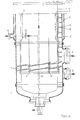
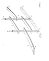
- FIG. 1 A corresponding construction is shown in Figure 1 and Figure 2.
- 1 means an outer body, 2 a heating jacket, 3 an inner body, 4 a holding rod, 5 heating of the inner body, 6 a guide vane, 7 a spacer, 8 a gas inlet, 9 a product inlet, 10 a support ring, 11 a pin of the holding rod, 12 a receiving opening in the support ring, 13 steam outlet from the inner body, 14 steam outlet from the heating jacket of the outer body, 15 a groove in the guide vane, 16 a lip inserted into the groove 15 and 17 a cover to which the holding rods 4 are fastened.
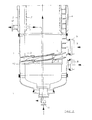
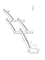
- Another embodiment of the swirl tube according to the invention is to arrange the guide vanes as a self-supporting structure around the enamelled inner body.
- the guide vanes have a foot at each of their two ends, which takes over the task of the holding rod and spacers (as listed in the previous design description).
- the foot has a pin at its end, while a corresponding groove is present in the top of the guide vane. This groove serves to receive the pins of the foot of the guide vane arranged above. Since the feet of the guide vane have different lengths, there is a helical arrangement leading around the inner body.
- Two adjacent guide vanes are connected to each other by a guide vane arranged above.
- One groove at the end of the one guide vane receives the pin of the foot of the guide vane arranged above and the groove of the adjacent guide vane receives the pin at the other end of the guide vane arranged above.
- the connection between the pin and the groove is made by gluing with the same material from which the guide vanes are made.
- the guide vane construction rests on an enamelled support ring at the lower end of the tube.
- This support ring is formed by a bulge-shaped bulge in the inner body.
- each guide vane Since the pin of the foot and the groove on the upper edge of each guide vane lie directly opposite one another, two guide vanes each overlap at the point of the pin or at the point of the groove.
- the edge of the guide blades facing the inner body is optionally carefully adapted to the enamelled surface of the inner body by mechanical reworking (grinding or milling) so that the edge of the guide blade lies as close as possible to the surface of the inner body.
- the edge of the guide vanes facing the enamelled inside of the outer body, as described for FIG. 1 and FIG. 2, has a groove into which e.g. a lip made of polytetrafluoroethylene is inserted and glued to the guide vane.
- a lip made of polytetrafluoroethylene is inserted and glued to the guide vane. The job of this lip is the same as previously explained.
- 1 mean an outer body, 2 a heating jacket, 3 an inner body, 4 a guide vane, 5 a gas inlet, 9 a product inlet, 10 a support ring, 11 steam inlet for heating the inner body, 12 steam outlet from the heating jacket of the outer body, 13 a groove in the outer edge the guide vane, 14 a lip inserted into the groove 13.
Landscapes
- Engineering & Computer Science (AREA)
- Mechanical Engineering (AREA)
- General Engineering & Computer Science (AREA)
- Life Sciences & Earth Sciences (AREA)
- Microbiology (AREA)
- Drying Of Solid Materials (AREA)
- Processing And Handling Of Plastics And Other Materials For Molding In General (AREA)
Claims (3)
Priority Applications (1)
| Application Number | Priority Date | Filing Date | Title |
|---|---|---|---|
| AT83100333T ATE33184T1 (de) | 1982-01-29 | 1983-01-17 | Vorrichtung zum erwaermen oder kuehlen und insbesondere zum trocknen feinteiliger feststoffe. |
Applications Claiming Priority (2)
| Application Number | Priority Date | Filing Date | Title |
|---|---|---|---|
| DE19823202954 DE3202954A1 (de) | 1982-01-29 | 1982-01-29 | Vorrichtung zum erwaermen oder kuehlen und insbesondere zum trocknen feinteiliger feststoffe |
| DE3202954 | 1982-01-29 |
Publications (3)
| Publication Number | Publication Date |
|---|---|
| EP0085331A2 EP0085331A2 (fr) | 1983-08-10 |
| EP0085331A3 EP0085331A3 (en) | 1984-11-07 |
| EP0085331B1 true EP0085331B1 (fr) | 1988-03-23 |
Family
ID=6154270
Family Applications (1)
| Application Number | Title | Priority Date | Filing Date |
|---|---|---|---|
| EP83100333A Expired EP0085331B1 (fr) | 1982-01-29 | 1983-01-17 | Dispositif de chauffage ou de refroidissement, notamment pour le séchage des matières pulvérulentes |
Country Status (4)
| Country | Link |
|---|---|
| US (1) | US4502230A (fr) |
| EP (1) | EP0085331B1 (fr) |
| AT (1) | ATE33184T1 (fr) |
| DE (2) | DE3202954A1 (fr) |
Families Citing this family (3)
| Publication number | Priority date | Publication date | Assignee | Title |
|---|---|---|---|---|
| US4594793A (en) * | 1984-08-16 | 1986-06-17 | The United States Of America As Represented By The United States Department Of Energy | Drying of pulverized material with heated condensible vapor |
| US7451663B2 (en) * | 2006-08-30 | 2008-11-18 | Kennametal Inc. | Wear-resistant flow meter tube |
| FR2976192B1 (fr) * | 2011-06-07 | 2016-07-29 | Commissariat Energie Atomique | Reacteur solide / gaz caloporteur et reactif comprenant un conduit helicoidal dans lequel le solide et le gaz circulent a contre-courant |
Family Cites Families (8)
| Publication number | Priority date | Publication date | Assignee | Title |
|---|---|---|---|---|
| DE1066955B (de) * | 1959-10-08 | Ruhrchemie Aktiengesellschaft, Oberhausen (Rhld.)-Holten | Verfahren und Vorrichtung zum Erwärmen oder Kühlen, insbesondere Trocknen, feinteiliger Stoffe | |
| FR528407A (fr) * | 1920-12-10 | 1921-11-12 | Charles Calloud | Séchoir automatique pour matière divisée |
| US2911730A (en) * | 1955-03-19 | 1959-11-10 | Ruhrchemie Ag | Drying of divided solid materials |
| US3068584A (en) * | 1957-07-12 | 1962-12-18 | Ruhrchemie Ag | Process for the treatment of divided materials |
| US2983051A (en) * | 1957-10-28 | 1961-05-09 | Dravo Corp | Apparatus for cooling particulate materials |
| US3254425A (en) * | 1962-08-20 | 1966-06-07 | Carrier Mfg Co | Elevator drier |
| DE2432627C3 (de) * | 1974-07-06 | 1979-03-22 | Hoechst Ag, 6000 Frankfurt | Verfahren und Vorrichtung zur Temperaturbehandlung eines Gemisches von !einteiligen festen Stoffen und Gasen |
| US4381819A (en) * | 1979-09-14 | 1983-05-03 | Paolino Ralph J | Flue heat reclaimer |
-
1982
- 1982-01-29 DE DE19823202954 patent/DE3202954A1/de not_active Withdrawn
- 1982-09-30 US US06/431,974 patent/US4502230A/en not_active Expired - Fee Related
-
1983
- 1983-01-17 EP EP83100333A patent/EP0085331B1/fr not_active Expired
- 1983-01-17 DE DE8383100333T patent/DE3376088D1/de not_active Expired
- 1983-01-17 AT AT83100333T patent/ATE33184T1/de active
Also Published As
| Publication number | Publication date |
|---|---|
| US4502230A (en) | 1985-03-05 |
| EP0085331A3 (en) | 1984-11-07 |
| DE3376088D1 (en) | 1988-04-28 |
| ATE33184T1 (de) | 1988-04-15 |
| DE3202954A1 (de) | 1983-08-11 |
| EP0085331A2 (fr) | 1983-08-10 |
Similar Documents
| Publication | Publication Date | Title |
|---|---|---|
| DE3630536C2 (fr) | ||
| EP2554932B1 (fr) | Réacteur tubulaire pour le traitement thermique de biomasse | |
| DE2939828A1 (de) | Verfahren und einrichtung zum flaechenverteilten streubeschichten von unterlagenoberflaechen mit partikeln | |
| DE102004045770B3 (de) | Trockeneisstrahlvorrichtung | |
| DE2707809C3 (de) | Vorrichtung zum Überziehen von Granulat | |
| DE2160962C3 (de) | Trommeltrockner zum Trocknen von Schlamm | |
| DE2430145C3 (fr) | ||
| EP0537311B1 (fr) | Evaporateur a couche mince en materiau resistant a la corrosion | |
| WO1992021436A1 (fr) | Dispositif de dispersion, suspension ou emulsion de gaz, liquides et/ou matieres solides coulantes | |
| EP0085331B1 (fr) | Dispositif de chauffage ou de refroidissement, notamment pour le séchage des matières pulvérulentes | |
| EP0170996B1 (fr) | Procédé et dispositif pour enrober des déchets, en particulier radioactifs, dans un liant | |
| CH667221A5 (de) | Desintegratoranlage. | |
| DE4000571C1 (fr) | ||
| DE3424841C2 (de) | Wirbelschichtapparat mit einer Vorrichtung zur Erzeugung einer gerichteten Feststoffströmung in der Wirbelschicht | |
| EP0124505A1 (fr) | Dispositif pour fabriquer des granulés à partir de fusions plastiques | |
| DE19629824C2 (de) | Vorrichtung zur Befeuchtung von Feststoffen in einer Fördereinrichtung | |
| DE1956241C3 (de) | Kühlmischer zum Aufbereiten von Kunststoffen | |
| DE1941831A1 (de) | Mischmaschine | |
| DE3424836C2 (fr) | ||
| DE2903323C2 (de) | Beheizte Vorrichtung zum Fördern und/oder Dosieren körniger, feuchter Stoffe | |
| DE3887946T2 (de) | Drehbarer Arbeitsapparat und Verfahren für extensives und dispersives Mischen. | |
| DE2634513C3 (de) | Vorrichtung zum Trocknen disperser Stoffe in einer zylinderförmigen Kammer | |
| AT201505B (de) | Einrichtung zum Fördern von pulverförmigem Gut | |
| DE3731595A1 (de) | Verfahren zur thermischen behandlung von schuettguetern und einrichtungen zur ausuebung des verfahrens | |
| DD262329A3 (de) | Waschstrecke fuer eine kontinuierliche benetzung und saeuberung von plastmuell |
Legal Events
| Date | Code | Title | Description |
|---|---|---|---|
| PUAI | Public reference made under article 153(3) epc to a published international application that has entered the european phase |
Free format text: ORIGINAL CODE: 0009012 |
|
| AK | Designated contracting states |
Designated state(s): AT BE DE FR GB IT NL SE |
|
| PUAL | Search report despatched |
Free format text: ORIGINAL CODE: 0009013 |
|
| AK | Designated contracting states |
Designated state(s): AT BE DE FR GB IT NL SE |
|
| 17P | Request for examination filed |
Effective date: 19841129 |
|
| ITF | It: translation for a ep patent filed | ||
| GRAA | (expected) grant |
Free format text: ORIGINAL CODE: 0009210 |
|
| AK | Designated contracting states |
Kind code of ref document: B1 Designated state(s): AT BE DE FR GB IT NL SE |
|
| REF | Corresponds to: |
Ref document number: 33184 Country of ref document: AT Date of ref document: 19880415 Kind code of ref document: T |
|
| REF | Corresponds to: |
Ref document number: 3376088 Country of ref document: DE Date of ref document: 19880428 |
|
| ET | Fr: translation filed | ||
| GBT | Gb: translation of ep patent filed (gb section 77(6)(a)/1977) | ||
| BECA | Be: change of holder's address |
Free format text: 880323 *HOECHST A.G.:POSTFACH 80 03 20, 6230 FRANKFURT |
|
| BECH | Be: change of holder |
Free format text: 880323 *HOECHST A.G. |
|
| PLBE | No opposition filed within time limit |
Free format text: ORIGINAL CODE: 0009261 |
|
| STAA | Information on the status of an ep patent application or granted ep patent |
Free format text: STATUS: NO OPPOSITION FILED WITHIN TIME LIMIT |
|
| PGFP | Annual fee paid to national office [announced via postgrant information from national office to epo] |
Ref country code: NL Payment date: 19890131 Year of fee payment: 11 |
|
| 26N | No opposition filed | ||
| PGFP | Annual fee paid to national office [announced via postgrant information from national office to epo] |
Ref country code: SE Payment date: 19911219 Year of fee payment: 10 |
|
| PGFP | Annual fee paid to national office [announced via postgrant information from national office to epo] |
Ref country code: FR Payment date: 19911224 Year of fee payment: 10 |
|
| PGFP | Annual fee paid to national office [announced via postgrant information from national office to epo] |
Ref country code: GB Payment date: 19920107 Year of fee payment: 10 |
|
| PGFP | Annual fee paid to national office [announced via postgrant information from national office to epo] |
Ref country code: BE Payment date: 19920114 Year of fee payment: 10 |
|
| PGFP | Annual fee paid to national office [announced via postgrant information from national office to epo] |
Ref country code: AT Payment date: 19920120 Year of fee payment: 10 |
|
| PGFP | Annual fee paid to national office [announced via postgrant information from national office to epo] |
Ref country code: DE Payment date: 19920213 Year of fee payment: 10 |
|
| PG25 | Lapsed in a contracting state [announced via postgrant information from national office to epo] |
Ref country code: AT Effective date: 19930117 Ref country code: GB Effective date: 19930117 |
|
| PG25 | Lapsed in a contracting state [announced via postgrant information from national office to epo] |
Ref country code: SE Effective date: 19930118 |
|
| PG25 | Lapsed in a contracting state [announced via postgrant information from national office to epo] |
Ref country code: BE Effective date: 19930131 |
|
| BERE | Be: lapsed |
Owner name: HOECHST A.G. Effective date: 19930131 |
|
| PG25 | Lapsed in a contracting state [announced via postgrant information from national office to epo] |
Ref country code: NL Effective date: 19930801 |
|
| GBPC | Gb: european patent ceased through non-payment of renewal fee |
Effective date: 19930117 |
|
| NLV4 | Nl: lapsed or anulled due to non-payment of the annual fee | ||
| PG25 | Lapsed in a contracting state [announced via postgrant information from national office to epo] |
Ref country code: FR Effective date: 19930930 |
|
| PG25 | Lapsed in a contracting state [announced via postgrant information from national office to epo] |
Ref country code: DE Effective date: 19931001 |
|
| REG | Reference to a national code |
Ref country code: FR Ref legal event code: ST |
|
| EUG | Se: european patent has lapsed |
Ref document number: 83100333.0 Effective date: 19930810 |