EP0085366A1 - Procédé et dispositif pour fabriquer des cellules tridimensionnelles en matériau de construction solidifiable - Google Patents
Procédé et dispositif pour fabriquer des cellules tridimensionnelles en matériau de construction solidifiable Download PDFInfo
- Publication number
- EP0085366A1 EP0085366A1 EP83100514A EP83100514A EP0085366A1 EP 0085366 A1 EP0085366 A1 EP 0085366A1 EP 83100514 A EP83100514 A EP 83100514A EP 83100514 A EP83100514 A EP 83100514A EP 0085366 A1 EP0085366 A1 EP 0085366A1
- Authority
- EP
- European Patent Office
- Prior art keywords
- formwork
- cell
- building material
- room cell
- room
- Prior art date
- Legal status (The legal status is an assumption and is not a legal conclusion. Google has not performed a legal analysis and makes no representation as to the accuracy of the status listed.)
- Granted
Links
- 239000004566 building material Substances 0.000 title claims abstract description 31
- 238000004519 manufacturing process Methods 0.000 title claims abstract description 10
- 238000000034 method Methods 0.000 title claims description 25
- 238000005086 pumping Methods 0.000 claims abstract description 6
- 238000009415 formwork Methods 0.000 claims description 83
- 239000007788 liquid Substances 0.000 claims description 18
- 239000011150 reinforced concrete Substances 0.000 claims description 4
- 230000002787 reinforcement Effects 0.000 claims description 4
- 230000000284 resting effect Effects 0.000 claims 1
- 238000000465 moulding Methods 0.000 abstract description 5
- 239000012530 fluid Substances 0.000 abstract 3
- 230000003014 reinforcing effect Effects 0.000 abstract 1
- 210000004027 cell Anatomy 0.000 description 70
- 239000004567 concrete Substances 0.000 description 10
- 238000010276 construction Methods 0.000 description 3
- 229910000831 Steel Inorganic materials 0.000 description 2
- 238000005266 casting Methods 0.000 description 2
- 230000002706 hydrostatic effect Effects 0.000 description 2
- 239000000463 material Substances 0.000 description 2
- 238000005096 rolling process Methods 0.000 description 2
- 239000010959 steel Substances 0.000 description 2
- XLYOFNOQVPJJNP-UHFFFAOYSA-N water Substances O XLYOFNOQVPJJNP-UHFFFAOYSA-N 0.000 description 2
- 241001503987 Clematis vitalba Species 0.000 description 1
- 230000015572 biosynthetic process Effects 0.000 description 1
- 210000002421 cell wall Anatomy 0.000 description 1
- 230000008878 coupling Effects 0.000 description 1
- 238000010168 coupling process Methods 0.000 description 1
- 238000005859 coupling reaction Methods 0.000 description 1
- 230000000694 effects Effects 0.000 description 1
- 239000003365 glass fiber Substances 0.000 description 1
- 230000005484 gravity Effects 0.000 description 1
- 238000009499 grossing Methods 0.000 description 1
- 238000009417 prefabrication Methods 0.000 description 1
- 238000002360 preparation method Methods 0.000 description 1
- 238000009416 shuttering Methods 0.000 description 1
- 238000009423 ventilation Methods 0.000 description 1
Images


Classifications
-
- B—PERFORMING OPERATIONS; TRANSPORTING
- B28—WORKING CEMENT, CLAY, OR STONE
- B28B—SHAPING CLAY OR OTHER CERAMIC COMPOSITIONS; SHAPING SLAG; SHAPING MIXTURES CONTAINING CEMENTITIOUS MATERIAL, e.g. PLASTER
- B28B7/00—Moulds; Cores; Mandrels
- B28B7/22—Moulds for making units for prefabricated buildings, i.e. units each comprising an important section of at least two limiting planes of a room or space, e.g. cells; Moulds for making prefabricated stair units
-
- B—PERFORMING OPERATIONS; TRANSPORTING
- B28—WORKING CEMENT, CLAY, OR STONE
- B28B—SHAPING CLAY OR OTHER CERAMIC COMPOSITIONS; SHAPING SLAG; SHAPING MIXTURES CONTAINING CEMENTITIOUS MATERIAL, e.g. PLASTER
- B28B7/00—Moulds; Cores; Mandrels
- B28B7/08—Moulds provided with means for tilting or inverting
Definitions
- the invention relates to a method for manufacturing room cells according to the preamble of claim 1.
- the method according to the invention can be applied to solidifying materials which, for example glass fiber or reinforced steel reinforced concrete, already contain their reinforcement when poured into the form space of a formwork, or are introduced and vibrated after inserting a reinforcement cage.
- solidifying materials for example glass fiber or reinforced steel reinforced concrete
- room-sized structures are produced which either form larger buildings with several further room cells according to the room cell construction or are set up individually, for example as prefabricated garages can be used.
- This prefabricated construction enables the production of the room cells according to the invention in large quantities with a high degree of mechanization and rationalization in mostly room cell formworks that can be heated for the rapid hardening of the solidifying building material and which are then often part of a production line. After completion, the room cells are generally five-sided buildings.
- the method according to the invention enables the production of such room cells with all five wall or ceiling and floor panes in a monolithic design, but can also be applied to room cells in which one or more panes are missing or, for example, the floor pan is prefabricated and then often kept on roll pallets will.
- the production of such room cells has to make do with as little manual work as possible in order to take advantage of the prefabricated construction.
- the room cell production must also do this ate reduce subsequent completion operations by a formwork as smooth as possible and, therefore, planar form of the visible surfaces in the formwork for the inevitable M.
- the first step of this process has the advantage that when the building material is poured into the mold spaces which are closed on all sides, the mold floors and walls are inclined only vertically or only inclined against the horizontal. As a result, the formation of air pockets and water pockets in the hardened building material can be largely avoided in a simple manner, so that the space cell panes produced in the closed mold rooms only have visible formwork surfaces that are smooth.
- the disadvantage is that the liquid building material after filling the formwork in the second process step in the open-topped open space of the longitudinal wall of the room cell must be carefully removed in order to achieve a smooth visible surface there too. That means a lot of work.
- the level of rationalization that can be achieved is already unusually low due to the multi-stage filling and hardening process.
- Method (P 28 45 109.1) from which the invention is based is based; it is based on the known method and aims to fill the room cell in one operation with a liquid building material and to remove it from the formwork with a roller pallet without using a lifting device before it hardens in the horizontal position.
- This method has the advantage that it leaves all visible surfaces of the room cell smooth. But since the filling of the liquid building material takes place through an open mold space, the filling must also be balanced in this mold space before the formwork lid can be closed. The process is therefore more rational than its model, but as a result does not allow any labor savings and is therefore still too low in terms of rationalization. It is also disadvantageous that the tilting must take place through a large arc angle. Since the weights to be mastered here are made up of the weight of the formwork and the building material filling, they are difficult to master in terms of design.
- the invention has for its object to achieve a higher degree of rationalization in the latter method, without having to give up its main advantages, namely in particular that the hardened room cell only has smooth formwork visible surfaces.
- the liquid building material is poured into the formwork, which is closed on all sides, using a special system which can have one or more pouring or pumping channels and one or more risers depending on the arrangement of the shape and design of the room cell.
- a special system which can have one or more pouring or pumping channels and one or more risers depending on the arrangement of the shape and design of the room cell.
- the last-mentioned advantage of the invention is preferably ensured in that the mold is inclined in preparation for filling by about 20-25 ° relative to the horizontal, so that the mold spaces for incident space cell panes are limited by walls with this slope.
- Such an inclination is not only due to the effect of avoiding air pockets and water pockets in the material of the room cell that has been attributed to it; at the same time, it reflects the inclination of an inclined plane on which the room cell cannot slip off its base with the friction coefficients customary for concrete.
- the advantage is that the usual pallets can be used and special measures for locking the room cell on the pallet need not be taken.
- This inclination is used in a further embodiment of the method according to the invention to support demoulding with forces which result from the weight component of the space cell falling in the inclination.
- the hardened room cell is transported out of the formwork in the direction of incidence over the room cell edge arranged downward in the form of the formwork.
- the utilization of the weight component of the room cell falling in the direction of removal from the formwork then facilitates the removal of the finished room cell from the inner formwork, in particular when the formwork can be removed over a transverse edge of the room cell.
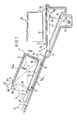
- a track 3 is laid on an inclined plane 1 with an inclination angle of approximately 20 ° relative to the horizontal 2. It leads to a scaffold 6 erected on the inclined plane and enables the transport of rolling pallets 16 along the inclined plane 1.
- the scaffold 6 carries a merely schematically represented internal formwork 7, which is rigid according to the exemplary embodiment shown, but also for shuttering in and out movable formwork parts' can have.
- Short-stroke cylinders 8 are connected to a frame 9, which closes the mold space 12, which is delimited on the inside by the formwork 7 and on the outside by an outer formwork 14, on its end face 11.
- the outer formwork of the mold space 12 for the room cell floor 15 is a roller pallet 16 of conventional design, which has a support frame and trolleys 17, 18 which run on the track 3.
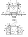
- the molding space for the end wall 19 of the space cell, generally designated 20, is delimited by an external control panel 21.
- This formwork panel is articulated via a joint 22 with a vertical joint axis to an outer formwork panel 23 and can be demolded via a lever 24 with a hydraulic thrust piston gear 25 from the shift position shown in solid lines.
- the double arrow 26 indicates the pivoting direction, a position of the formwork panel 21 being indicated in dash-dotted lines at 27, which position is assumed after the formwork has been removed.
- the formwork panel 23 corresponds to the formwork panel 28 which is parallel to it.
- the formwork panels 23 and 28 are mounted in steel frames 29, 30, which in turn have trolleys 31, 32, 33, 34 on rails 35, 36 in the direction of the double arrows 37; 38 are movable.
- the double tracks 35, 36 run perpendicular to the direction of track 3, the rails of which in 2 at 39 and 40 are shown.
- the formwork walls 23, 28 delimit the mold spaces for the longitudinal walls 41, 42 of the spatial cell, which is thus a five-sided closed space body except for the front end opening.
- the fifth side is formed by the ceiling 43, which is shut off to the outside with a two-part ceiling formwork 44, 45.
- Each slab formwork part 44, 45 can be moved via a lever gear 46, 47 in accordance with the double arrows 48, 49 with the aid of thrust piston gears 50, 51 into the broken-line formwork position and the switch position shown in solid lines.
- the roller pallet 16 On the front side 53, the roller pallet 16 carries a coupling 54 for the connecting cable 56 of a winch 57, which is fastened behind the frame 6 at the head of the inclined plane 1.
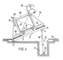
- a swivel platform 71 below the inner formwork 7, which has a swivel joint 72 with a swivel axis oriented transversely to the track 3.
- the underside 73 of the stage 71 opposite the joint 72 carries a bracket 74 for connecting a triple cylinder 75 which can be actuated hydraulically.
- the cylinder end is housed at 76 in a lined recess 77 in the hall floor.
- the cylinder, including its piston rod 78, can therefore be drawn in below the floor height indicated at 79.
- the lower transverse edge 60 assigned to the end wall 19 is oriented downward, resulting in only a flat inclination of the longitudinal walls of the room cells, the ceiling and the floor corresponding to the inclination of the inclined plane 1, while the transverse wall 19 is inclined slightly at the same angle to the vertical . All mold floors and walls are thus inclined, i.e. none of these parts are horizontal.
- the liquid building material is introduced into the mold via a pouring or pumping system, generally designated 62.
- a nozzle 64 for connecting a concrete line 65 is provided on the upper cross member 10a of the frame 10.
- a flexible hose 66 is connected to a corresponding opening in the cross member of the frame 10 for ventilation. Parts of the concrete remain in the socket 64 and in the hose 66, namely a sprue in the socket 64 and a riser in the hose 66.
- the liquid concrete is poured into the mold, which fills from the edge 60 and on which further risers can be provided as required to prevent air from being trapped.
- the frame 10 By actuating the thrust piston gear 8, the frame 10 is actuated in relation to the inner formwork 7 in the direction of the inclination of the inclined plane 1. At the same time the winch 57 is lowered so that the room cell 20 is stripped from the inner formwork 7. The weight component of the room cell 20 falling into level 1 helps here.
- the disconnected room cell 20 is moved onto the track section of the tilting tilting platform, which then swivels upwards, so that the parts assume their position shown in FIG.
- self-locking occurs between the room cell 20 and the pallet 16, so that the room cell need not be fastened to the pallet 16.
- the formwork shown in FIGS. 1 to 3 can be part of a production line which enables the finished spatial cells 20 to be transported transversely to the level 1 slide.
- the slab formwork 80 of the embodiment according to FIGS. 4 and 5 is formed in one piece and is therefore only operated with thrust piston drives 81 via angle levers 82 which are arranged on one side of the room cell formwork.
- the risers 66 and the inlets 65 are arranged on the opposite side of the room cell on the room cell longitudinal edge 83 located on the Höcl 1 .
- the formwork can be pivoted with the help of the thrust piston mechanism 75 about the joint 72 running parallel to the track 3 in this embodiment in such a way that the longitudinal edge 84 of the room cell is oriented downward between the room cell floor 15 and the longitudinal cell wall 42.
- the floor, ceiling and longitudinal wall disks of the room cell assume a slightly inclined position, which can correspond to that according to FIG. 1, while the room cell end wall is perpendicular. 4, the liquid building material is also introduced in a falling manner.
- the parts are first brought into the switch position shown in FIG. 4. Since the entire formwork, in this embodiment on the stage 'is housed 71, it is by extending the piston rod 78 and the cylinder of the thrust piston gear 75 in' .the g of Fi. 4 apparent Schwenkstellun g lverbracht.
- the thrust piston mechanism 75 is retracted, the ceiling formwork is removed, as is the end wall formwork not shown in the exemplary embodiment according to FIGS. 4 and 5, and the side wall formwork 23, 28 are moved down. Then the room cell 20 can be pulled off the inner formwork and is in its horizontal position.
- the stage 90 rests on a supporting frame, which in turn is clamped in guides 91 of a rocker 112 which are curved in circles.
- the guides 91 are made with the help of T) Tirsen 92, 93, 94, 95 and 96 and 97 in Kept clear.
- the guides are supported in rollers 101, 102, 103, 104, which are arranged distributed over the lower part of the circumference of the guides 91 and are mounted in a pit 105 under a hallway 106 on a common frame 107 and brackets 108, 109, 110, 111.
- the rails 40, 39 of the track 3 are laid on the stage 90.
- the roller pallet 16 also carries the rails 35, 36 for the scaffolding 29, 30 of the outer formwork 23, 28, which close off the formwork spaces for the longitudinal walls 41, 42 of the room cells.
- the ceiling formwork 80 is designed as in the exemplary embodiment according to FIG. 4.
- either the room cell is hardened to the extent that it can be disconnected, or the parts are prepared for casting the room cell.
- the space cell is tilted by means of the geared motor 100 by pivoting the guides 91 into a position which corresponds to the position of the stage 71 according to FIG. 4.
- the liquid concrete is introduced via the pouring system, which is not shown in FIG. 6, but possibly corresponds to FIG. 4.
- the room cell can then be moved into the position shown in FIG. 6 visible position can be pivoted back in this position to bring about the hardening of the concrete to the formwork strength.
- the building material can also be pumped in, preferably at the bottom edge of the room cell.
- the pumping system required for this differs essentially only from the gate system 62 in that the riser and gate are further apart.
- the method according to the invention therefore also has the advantage that the already existing and tried and tested formwork systems can be used according to the invention in a modified form by adding a swivel platform according to the type of FIG. 4 and a ceiling formwork, insofar as this is not already available . It is only necessary to bring the formwork into a slight inclination to the horizontal by rotating it around the longitudinal or transverse axis of the room cells.
Landscapes
- Engineering & Computer Science (AREA)
- Manufacturing & Machinery (AREA)
- Chemical & Material Sciences (AREA)
- Ceramic Engineering (AREA)
- Mechanical Engineering (AREA)
- Forms Removed On Construction Sites Or Auxiliary Members Thereof (AREA)
Applications Claiming Priority (2)
| Application Number | Priority Date | Filing Date | Title |
|---|---|---|---|
| DE19823202336 DE3202336A1 (de) | 1982-01-26 | 1982-01-26 | Verfahren und vorrichtung zum fertigen von raumzellen aus erstarrendem baustoff |
| DE3202336 | 1982-01-26 |
Publications (2)
| Publication Number | Publication Date |
|---|---|
| EP0085366A1 true EP0085366A1 (fr) | 1983-08-10 |
| EP0085366B1 EP0085366B1 (fr) | 1986-07-23 |
Family
ID=6153894
Family Applications (1)
| Application Number | Title | Priority Date | Filing Date |
|---|---|---|---|
| EP83100514A Expired EP0085366B1 (fr) | 1982-01-26 | 1983-01-21 | Procédé et dispositif pour fabriquer des cellules tridimensionnelles en matériau de construction solidifiable |
Country Status (3)
| Country | Link |
|---|---|
| EP (1) | EP0085366B1 (fr) |
| DE (1) | DE3202336A1 (fr) |
| ZA (1) | ZA83494B (fr) |
Cited By (1)
| Publication number | Priority date | Publication date | Assignee | Title |
|---|---|---|---|---|
| EP3910129A1 (fr) * | 2020-05-15 | 2021-11-17 | PBM Groupe | Procédé pour la réalisation d'une structure ou d'une partie de structure monobloc tridimensionnelle en béton et structure ou partie de structure tridimensionnelle en béton ainsi obtenue |
Families Citing this family (3)
| Publication number | Priority date | Publication date | Assignee | Title |
|---|---|---|---|---|
| DE3709315C2 (de) * | 1987-03-21 | 1996-04-25 | Nuklear Service Gmbh Gns | Verfahren zum Einlagern von radioaktiven Abfallstoffen |
| DE9107967U1 (de) * | 1991-06-28 | 1991-09-26 | Bau-Idee GmbH, 7036 Schönaich | Vorrichtung zur Herstellung von Stahlbeton-Raumzellen |
| DE202007007262U1 (de) | 2007-05-20 | 2008-10-02 | Schuchardt, Karl-Heinz | Schalungsvorrichtungen zur Herstellung monolithischer Betongussbauten |
Citations (3)
| Publication number | Priority date | Publication date | Assignee | Title |
|---|---|---|---|---|
| DE2363441A1 (de) * | 1972-12-22 | 1974-06-27 | Lely Nv C Van Der | Vorrichtung zur herstellung von raumkaesten fuer fertighaeuser |
| DE2462352B2 (de) * | 1974-01-05 | 1977-07-21 | Ausscheidung aus: 24 00 390 Betonbau GmbH, 6833 Waghäusel | Verfahren zur herstellung einer raumzelle aus stahlbeton und vorrichtung zur durchfuehrung des verfahrens |
| DE3037580A1 (de) * | 1980-10-04 | 1982-05-06 | J. Gärtner Stahlbau GmbH u. Co KG, 7502 Malsch | Vorrichtung zum herstellen von einseitig offenen raumzellen aus stahlbeton oder einem sonstigen aushaertbaren schuettgut |
Family Cites Families (4)
| Publication number | Priority date | Publication date | Assignee | Title |
|---|---|---|---|---|
| DE1434748A1 (de) * | 1964-09-25 | 1968-11-28 | Mueller Dipl Ing Gebhard | Gebaeude in Fertigbauweise |
| DE2400390B2 (de) * | 1974-01-05 | 1977-02-24 | B28B "7-08 | Verfahren zur herstellung einer raumzelle aus stahlbeton und vorrichtung zur durchfuehrung des verfahrens |
| DE2845106C2 (de) * | 1978-10-17 | 1984-07-12 | Lorenz 4600 Dortmund Kesting | Verfahren und Vorrichtung zum Herstellen von monolithischen Stahlbetonraumzellen, z.B. Fertiggaragen |
| DE3107793A1 (de) * | 1981-02-28 | 1982-09-16 | Hochtief Ag Vorm. Gebr. Helfmann, 4300 Essen | Schalungsvorrichtung zur herstellung von quaderfoermigen, stirnseitig offenen fertiggaragen aus stahlbeton |
-
1982
- 1982-01-26 DE DE19823202336 patent/DE3202336A1/de active Granted
-
1983
- 1983-01-21 EP EP83100514A patent/EP0085366B1/fr not_active Expired
- 1983-01-26 ZA ZA83494A patent/ZA83494B/xx unknown
Patent Citations (3)
| Publication number | Priority date | Publication date | Assignee | Title |
|---|---|---|---|---|
| DE2363441A1 (de) * | 1972-12-22 | 1974-06-27 | Lely Nv C Van Der | Vorrichtung zur herstellung von raumkaesten fuer fertighaeuser |
| DE2462352B2 (de) * | 1974-01-05 | 1977-07-21 | Ausscheidung aus: 24 00 390 Betonbau GmbH, 6833 Waghäusel | Verfahren zur herstellung einer raumzelle aus stahlbeton und vorrichtung zur durchfuehrung des verfahrens |
| DE3037580A1 (de) * | 1980-10-04 | 1982-05-06 | J. Gärtner Stahlbau GmbH u. Co KG, 7502 Malsch | Vorrichtung zum herstellen von einseitig offenen raumzellen aus stahlbeton oder einem sonstigen aushaertbaren schuettgut |
Cited By (2)
| Publication number | Priority date | Publication date | Assignee | Title |
|---|---|---|---|---|
| EP3910129A1 (fr) * | 2020-05-15 | 2021-11-17 | PBM Groupe | Procédé pour la réalisation d'une structure ou d'une partie de structure monobloc tridimensionnelle en béton et structure ou partie de structure tridimensionnelle en béton ainsi obtenue |
| FR3110188A1 (fr) * | 2020-05-15 | 2021-11-19 | Pbm Groupe | Procede pour la realisation d’une structure ou d’une partie de structure monobloc tridimensionnelle en beton et structure ou partie de structure tridimensionnelle en beton ainsi obtenue |
Also Published As
| Publication number | Publication date |
|---|---|
| DE3202336C2 (fr) | 1991-09-12 |
| EP0085366B1 (fr) | 1986-07-23 |
| DE3202336A1 (de) | 1983-07-28 |
| ZA83494B (en) | 1983-10-26 |
Similar Documents
| Publication | Publication Date | Title |
|---|---|---|
| DE2639812A1 (de) | Fertigbauelement sowie verfahren und einrichtung zu dessen herstellung | |
| EP2083977B1 (fr) | Système de coffrage pour le bétonnage d'éléments préfabriqués, comprenant un coffrage extérieur et un coffrage central | |
| DE2326069A1 (de) | Giessvorrichtung | |
| DE1948985A1 (de) | Vorgefertigter Gebaeudeteil und Verfahren zu dessen Herstellung | |
| EP3662116A1 (fr) | Procédé de fabrication d'un élément de plafond et coffrage de plafond | |
| DE2845106C2 (de) | Verfahren und Vorrichtung zum Herstellen von monolithischen Stahlbetonraumzellen, z.B. Fertiggaragen | |
| DE1684182A1 (de) | Verfahren zur Konstruktion von Gebaeuden aus dreidimensionalen Einzelteilen,Verfahren zur Herstellung dieser Teile und Drehform zum Giessen derselben | |
| EP0085366B1 (fr) | Procédé et dispositif pour fabriquer des cellules tridimensionnelles en matériau de construction solidifiable | |
| DE19525082A1 (de) | Wandelement für Hochbauten und Verfahren zu seiner Herstellung | |
| DE2400790C2 (de) | Verfahren und Vorrichtung zur Herstellung von Raumzellen aus Stahlbeton, z.B. Fertiggaragen | |
| DE1584637C3 (de) | Vorrichtung zum Herstellen einer großformatigen Bauplatte und Verwendung der Vorrichtung | |
| DE4424526A1 (de) | Fertigteil-Deckenplatte für Gebäude | |
| EP3832052A1 (fr) | Coffrage pour generer une porte ou fenetre dans un mur ou dalle en beton | |
| DE2252087C3 (de) | Schalung zur horizontalen Fertigung von Stahlbetonraumzellen, insbesondere von Fertiggaragen, welche einen Boden und eine offene Stirnseite aufweisen, und Verfahren zum Einbringen von Beton in die Schalung | |
| DE102017129383A1 (de) | Verfahren zur Herstellung eines mehrschichtigen Fertigbauelements | |
| CH655045A5 (de) | Schalungsvorrichtung zur herstellung von quaderfoermigen, stirnseitig offenen fertiggaragen aus stahlbeton. | |
| DE2805016C3 (de) | Verfahren und Batterieschalung zur Herstellung von Stahlbetonfertigteilen auf der Baustelle | |
| DE10326777A1 (de) | Stahlbetonraumzelle mit einer Bodenplatte und einem Hohlkörper | |
| DE3343808C2 (fr) | ||
| DE19514299A1 (de) | Verfahren und Vorrichtung zum selbsttätigen Herstellen von plattenförmigen Betonbauteilen | |
| DE3935076A1 (de) | Gleit- oder kletterschalung | |
| DE2101093C3 (de) | Vorrichtung zum Herstellen von insbesondere bewehrten, plattenförmigen Wand- und Deckenelementen aus Beton für den Fertigbau | |
| DE3212500C2 (fr) | ||
| CH615616A5 (en) | Shuttering for producing concrete floor beams | |
| DE2101093B2 (de) | Vorrichtung zum Herstellen von insbesondere bewehrten, plattenförmigen Wand- und Deckenelementen aus Beton für den Fertigbau |
Legal Events
| Date | Code | Title | Description |
|---|---|---|---|
| PUAI | Public reference made under article 153(3) epc to a published international application that has entered the european phase |
Free format text: ORIGINAL CODE: 0009012 |
|
| AK | Designated contracting states |
Designated state(s): BE CH FR IT LI NL |
|
| 17P | Request for examination filed |
Effective date: 19830712 |
|
| GRAA | (expected) grant |
Free format text: ORIGINAL CODE: 0009210 |
|
| AK | Designated contracting states |
Kind code of ref document: B1 Designated state(s): BE CH FR IT LI NL |
|
| PG25 | Lapsed in a contracting state [announced via postgrant information from national office to epo] |
Ref country code: IT Free format text: LAPSE BECAUSE OF FAILURE TO SUBMIT A TRANSLATION OF THE DESCRIPTION OR TO PAY THE FEE WITHIN THE PRESCRIBED TIME-LIMIT;WARNING: LAPSES OF ITALIAN PATENTS WITH EFFECTIVE DATE BEFORE 2007 MAY HAVE OCCURRED AT ANY TIME BEFORE 2007. THE CORRECT EFFECTIVE DATE MAY BE DIFFERENT FROM THE ONE RECORDED. Effective date: 19860723 |
|
| ET | Fr: translation filed | ||
| PLBE | No opposition filed within time limit |
Free format text: ORIGINAL CODE: 0009261 |
|
| STAA | Information on the status of an ep patent application or granted ep patent |
Free format text: STATUS: NO OPPOSITION FILED WITHIN TIME LIMIT |
|
| 26N | No opposition filed | ||
| BERE | Be: lapsed |
Owner name: KESTING LORENZ Effective date: 19870131 |
|
| PG25 | Lapsed in a contracting state [announced via postgrant information from national office to epo] |
Ref country code: NL Effective date: 19870801 |
|
| NLV4 | Nl: lapsed or anulled due to non-payment of the annual fee | ||
| PG25 | Lapsed in a contracting state [announced via postgrant information from national office to epo] |
Ref country code: FR Free format text: LAPSE BECAUSE OF NON-PAYMENT OF DUE FEES Effective date: 19870930 |
|
| REG | Reference to a national code |
Ref country code: FR Ref legal event code: ST |
|
| PG25 | Lapsed in a contracting state [announced via postgrant information from national office to epo] |
Ref country code: BE Effective date: 19890131 |
|
| PGFP | Annual fee paid to national office [announced via postgrant information from national office to epo] |
Ref country code: CH Payment date: 19900222 Year of fee payment: 8 |
|
| PG25 | Lapsed in a contracting state [announced via postgrant information from national office to epo] |
Ref country code: LI Effective date: 19910131 Ref country code: CH Effective date: 19910131 |
|
| REG | Reference to a national code |
Ref country code: CH Ref legal event code: PL |