EP3832052A1 - Coffrage pour generer une porte ou fenetre dans un mur ou dalle en beton - Google Patents
Coffrage pour generer une porte ou fenetre dans un mur ou dalle en beton Download PDFInfo
- Publication number
- EP3832052A1 EP3832052A1 EP19213624.0A EP19213624A EP3832052A1 EP 3832052 A1 EP3832052 A1 EP 3832052A1 EP 19213624 A EP19213624 A EP 19213624A EP 3832052 A1 EP3832052 A1 EP 3832052A1
- Authority
- EP
- European Patent Office
- Prior art keywords
- formwork
- recess
- bearing
- panel
- support bracket
- Prior art date
- Legal status (The legal status is an assumption and is not a legal conclusion. Google has not performed a legal analysis and makes no representation as to the accuracy of the status listed.)
- Withdrawn
Links
- 239000004567 concrete Substances 0.000 title claims abstract description 61
- 238000009416 shuttering Methods 0.000 title abstract description 9
- 238000009415 formwork Methods 0.000 claims abstract description 235
- 238000006073 displacement reaction Methods 0.000 claims abstract description 11
- 238000004519 manufacturing process Methods 0.000 claims description 7
- 230000000284 resting effect Effects 0.000 claims description 3
- 239000011178 precast concrete Substances 0.000 description 3
- 230000015572 biosynthetic process Effects 0.000 description 2
- 230000002349 favourable effect Effects 0.000 description 2
- 238000000034 method Methods 0.000 description 2
- 238000010276 construction Methods 0.000 description 1
- 230000001419 dependent effect Effects 0.000 description 1
- 230000005484 gravity Effects 0.000 description 1
- 238000010438 heat treatment Methods 0.000 description 1
- 230000007257 malfunction Effects 0.000 description 1
- 230000006641 stabilisation Effects 0.000 description 1
- 238000011105 stabilization Methods 0.000 description 1
- 230000007704 transition Effects 0.000 description 1
Images


Classifications
-
- E—FIXED CONSTRUCTIONS
- E04—BUILDING
- E04G—SCAFFOLDING; FORMS; SHUTTERING; BUILDING IMPLEMENTS OR AIDS, OR THEIR USE; HANDLING BUILDING MATERIALS ON THE SITE; REPAIRING, BREAKING-UP OR OTHER WORK ON EXISTING BUILDINGS
- E04G15/00—Forms or shutterings for making openings, cavities, slits, or channels
- E04G15/02—Forms or shutterings for making openings, cavities, slits, or channels for windows, doors, or the like
-
- B—PERFORMING OPERATIONS; TRANSPORTING
- B28—WORKING CEMENT, CLAY, OR STONE
- B28B—SHAPING CLAY OR OTHER CERAMIC COMPOSITIONS; SHAPING SLAG; SHAPING MIXTURES CONTAINING CEMENTITIOUS MATERIAL, e.g. PLASTER
- B28B7/00—Moulds; Cores; Mandrels
- B28B7/16—Moulds for making shaped articles with cavities or holes open to the surface, e.g. with blind holes
- B28B7/18—Moulds for making shaped articles with cavities or holes open to the surface, e.g. with blind holes the holes passing completely through the article
- B28B7/186—Moulds for making shaped articles with cavities or holes open to the surface, e.g. with blind holes the holes passing completely through the article for plates, panels or similar sheet- or disc-shaped objects, also flat oblong moulded articles with lateral openings, e.g. panels with openings for doors or windows, grated girders
-
- B—PERFORMING OPERATIONS; TRANSPORTING
- B28—WORKING CEMENT, CLAY, OR STONE
- B28B—SHAPING CLAY OR OTHER CERAMIC COMPOSITIONS; SHAPING SLAG; SHAPING MIXTURES CONTAINING CEMENTITIOUS MATERIAL, e.g. PLASTER
- B28B7/00—Moulds; Cores; Mandrels
- B28B7/0002—Auxiliary parts or elements of the mould
- B28B7/0014—Fastening means for mould parts, e.g. for attaching mould walls on mould tables; Mould clamps
- B28B7/0017—Fastening means for mould parts, e.g. for attaching mould walls on mould tables; Mould clamps for attaching mould walls on mould tables
-
- B—PERFORMING OPERATIONS; TRANSPORTING
- B28—WORKING CEMENT, CLAY, OR STONE
- B28B—SHAPING CLAY OR OTHER CERAMIC COMPOSITIONS; SHAPING SLAG; SHAPING MIXTURES CONTAINING CEMENTITIOUS MATERIAL, e.g. PLASTER
- B28B7/00—Moulds; Cores; Mandrels
- B28B7/0029—Moulds or moulding surfaces not covered by B28B7/0058 - B28B7/36 and B28B7/40 - B28B7/465, e.g. moulds assembled from several parts
- B28B7/0035—Moulds characterised by the way in which the sidewalls of the mould and the moulded article move with respect to each other during demoulding
- B28B7/0041—Moulds characterised by the way in which the sidewalls of the mould and the moulded article move with respect to each other during demoulding the sidewalls of the mould being moved only parallelly away from the sidewalls of the moulded article
-
- B—PERFORMING OPERATIONS; TRANSPORTING
- B28—WORKING CEMENT, CLAY, OR STONE
- B28B—SHAPING CLAY OR OTHER CERAMIC COMPOSITIONS; SHAPING SLAG; SHAPING MIXTURES CONTAINING CEMENTITIOUS MATERIAL, e.g. PLASTER
- B28B7/00—Moulds; Cores; Mandrels
- B28B7/0029—Moulds or moulding surfaces not covered by B28B7/0058 - B28B7/36 and B28B7/40 - B28B7/465, e.g. moulds assembled from several parts
- B28B7/0035—Moulds characterised by the way in which the sidewalls of the mould and the moulded article move with respect to each other during demoulding
- B28B7/0044—Moulds characterised by the way in which the sidewalls of the mould and the moulded article move with respect to each other during demoulding the sidewalls of the mould being only tilted away from the sidewalls of the moulded article, e.g. moulds with hingedly mounted sidewalls
-
- B—PERFORMING OPERATIONS; TRANSPORTING
- B28—WORKING CEMENT, CLAY, OR STONE
- B28B—SHAPING CLAY OR OTHER CERAMIC COMPOSITIONS; SHAPING SLAG; SHAPING MIXTURES CONTAINING CEMENTITIOUS MATERIAL, e.g. PLASTER
- B28B7/00—Moulds; Cores; Mandrels
- B28B7/24—Unitary mould structures with a plurality of moulding spaces, e.g. moulds divided into multiple moulding spaces by integratable partitions, mould part structures providing a number of moulding spaces in mutual co-operation
- B28B7/241—Detachable assemblies of mould parts providing only in mutual co-operation a number of complete moulding spaces
- B28B7/243—Detachable assemblies of mould parts providing only in mutual co-operation a number of complete moulding spaces for making plates, panels or similar sheet- or disc-shaped objects
-
- E—FIXED CONSTRUCTIONS
- E04—BUILDING
- E04G—SCAFFOLDING; FORMS; SHUTTERING; BUILDING IMPLEMENTS OR AIDS, OR THEIR USE; HANDLING BUILDING MATERIALS ON THE SITE; REPAIRING, BREAKING-UP OR OTHER WORK ON EXISTING BUILDINGS
- E04G11/00—Forms, shutterings, or falsework for making walls, floors, ceilings, or roofs
- E04G11/06—Forms, shutterings, or falsework for making walls, floors, ceilings, or roofs for walls, e.g. curved end panels for wall shutterings; filler elements for wall shutterings; shutterings for vertical ducts
- E04G11/08—Forms, which are completely dismantled after setting of the concrete and re-built for next pouring
- E04G11/082—Retractable forms for the inside face of at least three walls
Definitions
- the invention further relates to a battery formwork with such a formwork and a further formwork element, a formwork space being provided between the formwork panel of the formwork and the further formwork element.
- a recess formwork can be used to form an opening for a window, a door or the like in a concrete component.
- the recess formwork is arranged on the formwork skins of an inner and an outer formwork.
- the recess formwork has a movable frame which is attached to a rigid inner frame. Links are formed on the outer circumference of the inner frame, which hold the frame sections of the recess formwork in an articulated manner. The links can be pivoted so that the recess formwork is reduced in size and so the outer formwork together with the recess formwork of the created concrete body can be peeled off. Spindles which can be lengthened or shortened are provided for pivoting the handlebars.
- demolding the concrete component is complex.
- the spindles must be adjusted so far that there is a sufficient distance between the frame sections of the recess formwork and the concrete component in order to be able to detach the formwork from the concrete body.
- a particular problem here is that the frame sections can adhere to the concrete component, as a result of which the formwork can be blocked from being pulled off.
- Another disadvantage is that the links and the spindles are exposed to high loads when concreting, which can lead to malfunctions.
- the object of the present invention is to alleviate or remedy at least individual disadvantages of the prior art.
- the aim of the invention is, in particular, to make it easier and more reliable to detach the concrete element from the formwork.
- a further aim of the invention can be to improve the transfer of loads during concreting.
- the stripping device has a displacement and tilting mechanism for moving the frame element in a direction parallel to the formwork panel and for tilting the frame element about a pivot axis running essentially parallel to the formwork panel.
- the sliding and tilting mechanism of the stripping device is actuated.
- the shifting and tilting mechanism is set up to shift the frame element in the direction parallel to the main plane of the formwork panel and at the same time to tilt the frame element about the pivot axis running parallel to the main plane of the formwork panel.
- the frame element cannot can only be moved along the inside of the panel, but also tilted away from the inside of the panel. This makes it much easier to separate the formwork and structural element after hardening. If the frame element adheres to the concrete element, the concrete element can still be separated from the formwork because the frame element is displaced and tilted at the same time. A blockage during demolding is thus reliably avoided. If the frame element does not adhere to the concrete element, it can be moved without tilting the frame element at the same time. However, it is essential that the stripping device is set up to enable both the displacement and the tilting of the frame element.
- the frame element can be tilted away from the formwork when the concrete element is separated from the formwork. As a result, the concrete element can be reliably removed from the formwork (or, conversely, the formwork can be pulled off the concrete element).
- the frame element In the formwork position, the frame element is preferably arranged essentially perpendicular to the inside of the formwork panel. If the frame element is tilted during stripping, the frame element is arranged in the stripping position at an angle to the inside of the formwork panel.
- the frame element can preferably be tilted by at least 2 degrees, in particular at least 4 degrees, particularly preferably at least 6 degrees, while simultaneously being displaced away from the concrete element.
- the displacement and tilting mechanism of the stripping device preferably has a longitudinal guide, in particular an elongated hole, and a guide element, in particular a bolt, mounted in it so as to be displaceable and pivotable, the longitudinal guide on one of Support bracket and bearing element and the guide element is provided on the other of the support bracket and bearing element.
- the longitudinal guide is preferably formed on the support bracket and the guide element on the bearing element.
- the reverse arrangement can also be provided.
- the frame element By shifting the guide element along the longitudinal guide with simultaneous pivoting of the guide element about the pivot axis, the frame element is shifted inward and tilted away from the formwork panel.
- the desired degrees of freedom of movement are thus achieved in a particularly simple manner.
- the transfer to the stripping position can be carried out particularly quickly, since laborious actuation of spindles as in the prior art is not necessary.
- the transition from the shuttering to the shuttering position can be jerky.
- all degrees of freedom of movement of the frame element except for the displacement along the formwork panel and the tilting about the pivot axis parallel to the formwork panel are blocked.
- the support bracket In order to release the tilting movement of the support bracket during the transfer into the stripping position and therefore not to block it, the support bracket according to a preferred embodiment variant has a rounded portion at the end area facing the pivot axis to free the pivoting of the support bracket.
- the recess formwork preferably has a securing element for securing the support bracket in the formwork position.
- the secured state of the securing element the recess formwork is secured against being transferred from the formwork position to the stripping position.
- the unlocked state of the securing element the transfer from the shutter position to the shutter position is released.
- the concrete element can be poured in the receiving space of the formwork adjacent to the formwork panel. After the concrete element has hardened, the securing element is brought into the unlocked state in order to be able to transfer the recess formwork from the formwork to the stripping position.
- the securing element can be connected to the bearing element via a releasable connection, in particular via a screw connection.
- the formwork can be prepared by loosening the detachable connection.
- the detachable connection is established to enable the concrete element to be poured with the recess.
- the releasable connection of the securing element can therefore be made and released reversibly, ie without any loss of function, and preferably without tools.
- the screw connection has a threaded bolt, in particular essentially in the center of the bearing element, the securing element having a holding opening for placing on the threaded bolt.
- the screw connection preferably has a retaining nut which fixes the securing element placed on the threaded bolt on the bearing element.
- the threaded bolt is preferably arranged essentially perpendicular to the main plane of the formwork panel, which on the one hand facilitates the placement of the securing element and on the other hand the attachment of the retaining nut. It is also favorable if the securing element has a holding plate on which the holding opening is formed.
- This embodiment has the particular advantage that the sliding and tilting mechanism in the secured state of the securing element can be covered at least partially, preferably essentially completely, by the retaining plate. This increases the safety during operation.
- the retaining plate is preferably arranged essentially perpendicular to the threaded bolt and essentially parallel to the formwork panel.
- the bearing element preferably has a bearing plate which is attached to the formwork panel.
- the retaining plate of the securing element has essentially the same shape and extension as the bearing plate of the bearing element, the retaining plate and the bearing plate being arranged essentially congruently in plan view, perpendicular to the panel.
- the bearing element in particular a bearing plate of the bearing element, is preferably fastened to the formwork panel via a screw connection, for example with a threaded bolt.
- a magnetic connection can also be provided.
- the securing element in a preferred embodiment has a first holding surface for contact with an outside of the support bracket facing away from the panel and / or a second holding surface for contact with an end face of the support bracket facing away from the frame element.
- the second holding surface of the securing element is preferably designed as a wedge surface. This design causes a reliable securing of the frame element in the shuttering position in order to enable the precise formation of the recess in the concrete element.
- the bearing element has at least one first wedge surface and the securing element has at least one second wedge surface, the second wedge surface of the securing element resting against the first wedge surface of the bearing element in the secured state of the securing element.
- the first and second wedge surfaces are arranged at an angle to the inside of the formwork panel, i.e. at an angle other than 90 degrees, for example at an angle of 70 or 110 degrees.
- the bearing element preferably has at least two, in particular four, first wedge surfaces and the securing element has at least two, in particular four, second wedge surfaces.
- the first and second wedge surfaces preferably diverge in the direction away from the inside of the formwork panel.
- the first wedge surfaces preferably delimit a receiving opening into which a section of the securing element, in particular a projection on the underside of a retaining plate of the securing element, is inserted with the second wedge surfaces.
- the first wedge surfaces form corresponding contact surfaces for the second wedge surfaces of the securing element in order to facilitate the attachment of the securing element to the bearing element. It is also advantageous that the first and second wedge surfaces bring about effective bracing of the securing element on the bearing element.
- the bearing element has at least two, preferably four, bearing points for mounting two, preferably four, support brackets. At least one pair of bearing points is preferably provided for two support brackets, which protrude in opposite directions from the bearing element. Thus, two opposite boundaries of the recess of the concrete element can be formed. Depending on the design, however, three support brackets can also lead away from three bearing points at right angles to one another in order to form three boundaries of a rectangular recess in the concrete element. Furthermore, four bearing points can be arranged in pairs at right angles to one another. If support brackets are arranged at all four bearing points, all four boundaries of a rectangular recess can be formed. Thus, two, three or four support brackets can be arranged at the bearing points of the bearing element, to which a corresponding number of frame elements are attached in order to form two, three or four boundaries of a rectangular recess in the concrete element.
- the bearing points each have at least one holding flange with a bearing opening.
- the retaining flange is preferably arranged essentially perpendicular to the formwork panel.
- the guide element, in particular the bolt, of the shifting and tilting mechanism is preferably mounted on the bearing opening. It is also favorable if the bolt is detachably attached to the bearing opening, in particular detachable without tools. The bolt can be secured to the bearing opening with a cotter pin.
- the associated bracket can be detached from the bearing element in a simple manner if the corresponding bearing point is not to be occupied by a bracket for the current application.
- the formwork has a further formwork panel, the formwork panel and the further formwork panel being pivotably connected to one another at their first end regions, so that the formwork panel and the further formwork panel can be converted from a standing state to a lying state.
- a "butterfly formwork" with two pivotable formwork elements is for example from the WO 2016/184947 A1 known.
- the two preferably rectangular formwork panels are each pivotably connected at a first end region, in particular on one of their longitudinal sides. For this purpose, an articulated connection can be provided between the first end regions of the formwork panels.
- Formwork panels can be transferred from a standing state, in which the formwork elements are preferably aligned essentially vertically, into a lying state, in which the formwork elements are preferably aligned essentially horizontally.
- the first end areas form the upper ends of the formwork elements and the second end areas form the lower ends of the formwork elements.
- the recess formwork can be mounted on the panel.
- the formwork is preferably used in a battery formwork which has a further formwork element, with a formwork space being provided between the formwork panel of the formwork and the further formwork element.
- the further formwork element can be a single formwork panel.
- two further formwork elements can be pivotably connected to one another at their first end regions, as was explained above in connection with a preferred embodiment of the formwork.
- the formwork space is formed between the formwork and one of the further formwork elements.
- a battery formwork can be expanded as required with formwork and further formwork elements in order to form several formwork spaces for the production of several concrete elements.
- the formwork can be arranged between two bulkheads of the battery formwork in the standing state of the formwork panels.
- the formwork panels are in the collapsed (i.e. essentially parallel side by side) state.
- a further formwork element is preferably arranged opposite the formwork panel, the recess formwork being located between the formwork panel and the further formwork element.
- the concrete element is preferably poured in a battery formwork which has the formwork and the further formwork element.
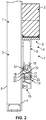
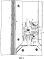
- Fig. 1 shows a formwork device, in the following for short formwork 1, for the production of a (in Fig. 2 apparent) concrete element 2, which is in particular a rectangular wall or ceiling element.
- the formwork 1 has a formwork panel, ie a formwork panel 3, which has an inside 4 to delimit a receiving space for concrete and an outside 5 facing away from the receiving space (cf. Fig. 2 ) having.
- the inside 4 and the outside 5 of the formwork panel 3 are essentially flat.
- On the inside 4 of the formwork panel 3 there is a recess formwork 6 with which a window or door recess 7 is formed on the concrete element 2.
- the recess formwork 6 has at least one frame element 8 which delimits a straight section of the recess 7.
- each frame element 8 is arranged at right angles to one another in order to define a rectangular recess 7.
- the frame elements 8 are each connected via at least one support bracket 9 to at least one bearing element 10, which is fastened to the inside 4 of the formwork panel 3.
- each frame element 8 is connected to two bearing elements 10 via two support brackets 9.
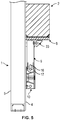
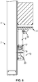
- a stripping device 11 is provided with which the recess formwork 6 from one in Fig. 1 and Fig. 2 Shutter position shown for concreting the concrete element in one in the Fig. 3, 4 Stripping position shown for releasing the concrete element 2 from the formwork 1 can be moved.
- the stripping device 11 has a shifting and tilting mechanism 12 which is set up to shift the frame element 8 in a direction 13 parallel to the formwork panel 3 (see double arrow 13 in FIG Fig. 3 ) and to tilt a pivot axis running essentially parallel to the formwork panel 3 (see double arrow 14 in Fig. 3 ).
- the pivot axis of the sliding and tilting mechanism 12 runs parallel to the longitudinal axis 15 of the frame element 8 (cf. Fig. 1 ).
- the displacement and tilting mechanism 12 of the stripping device 11 has a longitudinal guide 16, here an elongated hole, in which a guide element 17, here a bolt, is displaceable and pivotable.
- a guide element 17, here a bolt is displaceable and pivotable.
- the longitudinal guide 16 is provided on the support bracket 9 and the guide element 17 is provided on the bearing element 10.
- the support bracket 9 has a rounded portion 18 (i.e. a rounded outer contour) at the end area facing the pivot axis, adjacent to the inside 4 of the formwork panel 3, with which the pivoting of the support bracket 9 is released.
- the formwork 1 also has a (in Fig. 1 not shown) securing element 19 for securing the support bracket 9 in the switching position.
- the securing element 19 is connected to the bearing element 10 via a releasable connection, in the embodiment shown via a screw connection.
- the screw connection has a threaded bolt 20 which is fixed in the center of the bearing element 10.
- the securing element 19 has a holding opening 21 (cf. Fig. 8 ) to be placed on the threaded bolt 20.
- the securing element 19 also has a first holding surface 22 for contact with an outer side 9a of the support bracket 9 facing away from the formwork panel and a second holding surface 23 for contact with an end face 9b of the support bracket 9 facing away from the frame element 8.
- the bearing element 10 has a first wedge surface 24, on which a second wedge surface 25 of the securing element 19 rests in the locked state.
- the bearing element 10 has four bearing points 26 at which at least one support bracket 9 and up to four support brackets 9 (including a corresponding number of frame elements 8) are arranged.
- the bearing points 26 each have two retaining flanges 27 with bearing openings 28, to which a bolt 29 for the support bracket 9 can be detachably attached.
- the bolt 29 can be secured with a cotter pin 30.
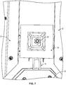
- the recess formwork also has corner formwork parts 31 which are arranged at the corners between two adjacent frame elements 8 of the recess formwork.
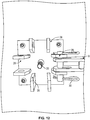
- FIG. 5 and Fig. 6 an embodiment variant is shown in which an additional mounting bracket 33 is provided between the frame element 8 and the support bracket 9.
- the corner formwork parts 31 of the recess formwork are first dismantled (cf. Fig. 7 ). Then a retaining nut 32 is loosened, which is screwed onto the end of the threaded bolt 20 in order to hold the securing element 19 on the bearing element 10 (cf. Fig. 8 ). The securing element 19 is then removed from the bearing element 10 (cf. Fig. 9 ). As a result, the displaceability and pivotability of the frame elements 8 is enabled. The concrete element 2 can thus be lifted away from the formwork 1. Already through the contact With the concrete element 2, the frame element 8 can be displaced and tilted in such a way that the lifting of the concrete element 2 is not blocked.
- Fig. 1 shows a schematic representation of an example from FIG WO 2017/174432 known battery formwork 34 with formwork devices 35 which have the formwork 1 described above.
- the battery mold 34 is used to manufacture (in Fig. 1 not shown) construction elements and in particular of precast concrete parts used for buildings.
- the battery mold 34 has a support frame 36 with support sections 37 spaced apart from one another.
- the number of support sections 37 in Fig. 1 is only to be regarded as an example and can be adapted to the circumstances.
- the battery formwork 34 comprises two support devices 38 in which the bulkheads 39 and the formwork devices 35 are accommodated in a hanging and movable manner, ie in the present embodiment they can be displaced.
- the shuttering devices 35 are located between the bulkheads 39.
- a cavity to be filled with concrete is formed between at least one bulkhead 39 and a shuttering device 35, the shuttering device 35 preferably carrying shuttering elements (not shown) which determine the contour of the precast concrete part.
- the formwork elements can, for example, delimit door or window cutouts and also seal the cavity filled with concrete during concreting.
- the formwork elements can be attached to the formwork device 35 with magnetic holders, for example.
- a heating device (not shown) and / or a vibrator (not shown) can also be mounted on the formwork device 35.
- the formwork device 35 is inserted between two bulkheads 39 and braced with them during concreting.
- the number of support devices 38 of the bulkheads 6 and the formwork devices 2 is to be regarded as only exemplary and can be varied depending on the circumstances.
- formwork devices 35 can be provided for concreting the outer walls, inner walls, the floor and the roof of a house, so that the components for an entire building can be produced simultaneously with the battery formwork 34.
- the bulkheads 39 and the formwork devices 35 are clamped between two support devices 40.
- the number of support devices 40 is also to be regarded as only exemplary and can be varied as required. At least one support device 40 is movably, ie displaceably in the present embodiment, received in the support devices 38.
- the formwork devices 35 and the support devices 40 can be connected to one another and braced in the concreting position by one or more rod-shaped connecting devices 41.
- the number of connecting devices 41 can be adapted to the circumstances. Instead of rod-shaped connecting devices 41, hydraulic connecting devices are also possible.
- the rod-shaped connecting devices 41 are, however, particularly robust and easy to handle.
- the battery formwork 34 has a lifting device 42 with which at least one of the formwork devices 35 can be transferred from the lowered concreting position to a raised transport position, in which the formwork device 35 can be conveyed in a direction essentially perpendicular to the lifting direction via a formwork device 35 in the concreting position is.
- the formwork devices 35 are hooked into the support devices 38 from above, so that in the hooked-in state in the concreting position they are spaced from the ground between the support sections 37.
- the design of the lifting device 42 can be adapted to requirements. If necessary, several lifting devices 9 can also be used.
- the lifting device 42 can be moved in a tensioning direction of the formwork devices 2 on two spaced-apart guide devices 43, which are designed here as running rails. Furthermore, the guide devices 43 are arranged above the support devices 38 and parallel to them. In order to make the battery molds 34 more compact, the formwork devices 35 are attached to the support devices 38 at their upper end.
- the formworks 1 according to the invention can be received in the battery formwork 34.
Landscapes
- Engineering & Computer Science (AREA)
- Mechanical Engineering (AREA)
- Manufacturing & Machinery (AREA)
- Chemical & Material Sciences (AREA)
- Ceramic Engineering (AREA)
- Architecture (AREA)
- Civil Engineering (AREA)
- Structural Engineering (AREA)
- Forms Removed On Construction Sites Or Auxiliary Members Thereof (AREA)
- Moulds, Cores, Or Mandrels (AREA)
Priority Applications (6)
| Application Number | Priority Date | Filing Date | Title |
|---|---|---|---|
| EP19213624.0A EP3832052A1 (fr) | 2019-12-04 | 2019-12-04 | Coffrage pour generer une porte ou fenetre dans un mur ou dalle en beton |
| PCT/EP2020/084573 WO2021110888A1 (fr) | 2019-12-04 | 2020-12-04 | Coffrage |
| US17/756,793 US12365112B2 (en) | 2019-12-04 | 2020-12-04 | Formwork |
| AU2020395900A AU2020395900A1 (en) | 2019-12-04 | 2020-12-04 | Formwork |
| CN202080081243.6A CN114729543B (zh) | 2019-12-04 | 2020-12-04 | 模板 |
| EP20816232.1A EP4069919B1 (fr) | 2019-12-04 | 2020-12-04 | Coffrage pour generer une porte ou fenetre dans un mur ou dalle en beton |
Applications Claiming Priority (1)
| Application Number | Priority Date | Filing Date | Title |
|---|---|---|---|
| EP19213624.0A EP3832052A1 (fr) | 2019-12-04 | 2019-12-04 | Coffrage pour generer une porte ou fenetre dans un mur ou dalle en beton |
Publications (1)
| Publication Number | Publication Date |
|---|---|
| EP3832052A1 true EP3832052A1 (fr) | 2021-06-09 |
Family
ID=68771562
Family Applications (2)
| Application Number | Title | Priority Date | Filing Date |
|---|---|---|---|
| EP19213624.0A Withdrawn EP3832052A1 (fr) | 2019-12-04 | 2019-12-04 | Coffrage pour generer une porte ou fenetre dans un mur ou dalle en beton |
| EP20816232.1A Active EP4069919B1 (fr) | 2019-12-04 | 2020-12-04 | Coffrage pour generer une porte ou fenetre dans un mur ou dalle en beton |
Family Applications After (1)
| Application Number | Title | Priority Date | Filing Date |
|---|---|---|---|
| EP20816232.1A Active EP4069919B1 (fr) | 2019-12-04 | 2020-12-04 | Coffrage pour generer une porte ou fenetre dans un mur ou dalle en beton |
Country Status (5)
| Country | Link |
|---|---|
| US (1) | US12365112B2 (fr) |
| EP (2) | EP3832052A1 (fr) |
| CN (1) | CN114729543B (fr) |
| AU (1) | AU2020395900A1 (fr) |
| WO (1) | WO2021110888A1 (fr) |
Families Citing this family (1)
| Publication number | Priority date | Publication date | Assignee | Title |
|---|---|---|---|---|
| CN117344967A (zh) * | 2023-10-12 | 2024-01-05 | 河南省第二建设集团有限公司 | 一种洞口内模模块化模具快速组拆装置及使用方法 |
Citations (7)
| Publication number | Priority date | Publication date | Assignee | Title |
|---|---|---|---|---|
| SU1780352A1 (ru) * | 1990-05-03 | 1996-05-20 | ОргстройНИИпроект | Опалубка для проемов |
| DE10219896C1 (de) | 2002-05-03 | 2003-08-21 | Peri Gmbh | Schalungssystem für Betonkörper |
| DE10320003A1 (de) * | 2003-05-06 | 2004-11-25 | Friedrich Ischebeck Gmbh | Positioniervorrichtung, Schalungseinheit und Wandschalung |
| DE102006021892A1 (de) * | 2006-05-11 | 2007-11-15 | Leonhard Weiss Gmbh & Co. Kg | System zum Herstellen einer Aussparung in einer Ortbetonschalung |
| DE102009055690A1 (de) * | 2009-11-25 | 2011-05-26 | Peri Gmbh | Ausschalvorrichtung |
| WO2016184947A1 (fr) | 2015-05-19 | 2016-11-24 | B.T. Innovation Gmbh | Dispositif de coffrage |
| WO2017174432A1 (fr) | 2016-04-08 | 2017-10-12 | B.T. Innovation Gmbh | Dispositif de coffrage |
Family Cites Families (17)
| Publication number | Priority date | Publication date | Assignee | Title |
|---|---|---|---|---|
| US2557631A (en) * | 1948-06-12 | 1951-06-19 | Patrick J Callan | Collapsible form for forming window or door openings in concrete walls |
| US4055321A (en) * | 1976-12-06 | 1977-10-25 | Symons Corporation | Inside concrete corewall form with particular three-way hinge assemblies therefor |
| CH632044A5 (en) * | 1978-07-11 | 1982-09-15 | Hans Schmid | Shuttering for window or door reveal |
| US4465257A (en) * | 1982-01-15 | 1984-08-14 | Symons Corporation | Concrete forming structure having a double hinge filler |
| US4520989A (en) * | 1984-04-23 | 1985-06-04 | Harsco Corporation | Concrete core-wall form and stripping assembly therefor |
| US4520988A (en) * | 1984-04-23 | 1985-06-04 | Harsco Corporation | Concrete core-wall form and stripping assembly therefor |
| US4650150A (en) * | 1985-04-19 | 1987-03-17 | Opako, S.A. | Mold apparatus for vertical elements of concrete |
| DE3536816A1 (de) * | 1985-10-16 | 1987-04-16 | Josef Maier | Schalung fuer rund- oder vieleckbauten |
| US5709808A (en) * | 1996-07-02 | 1998-01-20 | Lee; Kuo-An | Formwork to be used with a wall form assembly for forming a door opening in a concrete wall |
| DE19639038C1 (de) * | 1996-09-23 | 1998-06-04 | Doka Ind Gmbh | Kletterschalungssystem und Verfahren zum sukzessiven Betonieren von hohen vertikalen Wänden |
| US6712598B2 (en) * | 2000-11-20 | 2004-03-30 | Superior Concrete Fence Of Texas, Inc. | Mold battery with improved member separation |
| DE10212747B4 (de) * | 2002-03-22 | 2013-05-29 | Peri Gmbh | Ein- und Ausschalvorrichtung |
| US20070084984A1 (en) * | 2005-09-30 | 2007-04-19 | Randy Pauley | Collapsible inside corner form |
| US8182260B2 (en) * | 2007-06-25 | 2012-05-22 | Rampf Molds Industries, Inc. | Apparatus and method for forming tapered products |
| CN103774842A (zh) * | 2012-10-17 | 2014-05-07 | 中国葛洲坝集团股份有限公司 | 提升式方形竖井模板 |
| DE102016002435A1 (de) * | 2016-03-01 | 2017-09-07 | Rampf Formen Gmbh | Formrahmen mit verlagerbarer Formwand, Verwendung des Formrahmens sowie ein Formwandsystem mit verlagerbarer Formwand |
| CN108412193B (zh) * | 2018-04-24 | 2023-12-22 | 重庆科技学院 | 电梯井施工内模板伸缩装置 |
-
2019
- 2019-12-04 EP EP19213624.0A patent/EP3832052A1/fr not_active Withdrawn
-
2020
- 2020-12-04 EP EP20816232.1A patent/EP4069919B1/fr active Active
- 2020-12-04 US US17/756,793 patent/US12365112B2/en active Active
- 2020-12-04 CN CN202080081243.6A patent/CN114729543B/zh active Active
- 2020-12-04 AU AU2020395900A patent/AU2020395900A1/en not_active Abandoned
- 2020-12-04 WO PCT/EP2020/084573 patent/WO2021110888A1/fr not_active Ceased
Patent Citations (7)
| Publication number | Priority date | Publication date | Assignee | Title |
|---|---|---|---|---|
| SU1780352A1 (ru) * | 1990-05-03 | 1996-05-20 | ОргстройНИИпроект | Опалубка для проемов |
| DE10219896C1 (de) | 2002-05-03 | 2003-08-21 | Peri Gmbh | Schalungssystem für Betonkörper |
| DE10320003A1 (de) * | 2003-05-06 | 2004-11-25 | Friedrich Ischebeck Gmbh | Positioniervorrichtung, Schalungseinheit und Wandschalung |
| DE102006021892A1 (de) * | 2006-05-11 | 2007-11-15 | Leonhard Weiss Gmbh & Co. Kg | System zum Herstellen einer Aussparung in einer Ortbetonschalung |
| DE102009055690A1 (de) * | 2009-11-25 | 2011-05-26 | Peri Gmbh | Ausschalvorrichtung |
| WO2016184947A1 (fr) | 2015-05-19 | 2016-11-24 | B.T. Innovation Gmbh | Dispositif de coffrage |
| WO2017174432A1 (fr) | 2016-04-08 | 2017-10-12 | B.T. Innovation Gmbh | Dispositif de coffrage |
Also Published As
| Publication number | Publication date |
|---|---|
| CN114729543A (zh) | 2022-07-08 |
| US12365112B2 (en) | 2025-07-22 |
| WO2021110888A1 (fr) | 2021-06-10 |
| EP4069919A1 (fr) | 2022-10-12 |
| US20230009236A1 (en) | 2023-01-12 |
| AU2020395900A1 (en) | 2022-06-16 |
| EP4069919C0 (fr) | 2025-07-16 |
| CN114729543B (zh) | 2023-08-11 |
| EP4069919B1 (fr) | 2025-07-16 |
Similar Documents
| Publication | Publication Date | Title |
|---|---|---|
| EP3147094B1 (fr) | Moule pour mur vertical | |
| DE102015209157B4 (de) | Schalungseinrichtung und Batterieschalung mit dieser Schalungseinrichtung | |
| EP2083977B1 (fr) | Système de coffrage pour le bétonnage d'éléments préfabriqués, comprenant un coffrage extérieur et un coffrage central | |
| EP3572198B1 (fr) | Coffrage central pour un système de coffrage destiné à bétonner un corps de cloche | |
| EP3862510B1 (fr) | Support de compensation | |
| EP3439840B1 (fr) | Dispositif de coffrage | |
| EP3662116A1 (fr) | Procédé de fabrication d'un élément de plafond et coffrage de plafond | |
| DE2354696A1 (de) | Tragteil fuer bauformen | |
| EP3642428A1 (fr) | Tête d'appui à hauteur de support abaissable pour un appui de coffrage | |
| EP4069919B1 (fr) | Coffrage pour generer une porte ou fenetre dans un mur ou dalle en beton | |
| DE102021120441A1 (de) | System zur Schalung eines Wandelementes mit einem Verbund aus einer Schalung und einem Gerüstabschnitt | |
| DE2832295A1 (de) | Formtisch fuer betonfertigplatten | |
| EP4051473A1 (fr) | Dispositif de coffrage | |
| EP4051472B1 (fr) | Dispositif de coffrage | |
| EP3330448B1 (fr) | Dispositif et procédé de raccordement de deux composants dans une orientation déterminée relative ainsi que construction en béton | |
| DE69207966T2 (de) | Raumschalung | |
| DE2711116C2 (de) | Schalung zur Herstellung von Raumzellen, wie Fertiggaragen o.dgl. | |
| DE2808644C3 (de) | Vorrichtung zum Gießen von Betonbauelementen | |
| EP4636197A1 (fr) | Poutre horizontale, dispositif et procédé de coffrage d'un plancher en béton | |
| DE573853C (de) | Formeinrichtung mit einem auf einem Grundrahmen hergerichteten Formboden zur Herstellung kuenstlicher Bausteine, Bauplatten und sonstiger Formlinge | |
| EP4636196A1 (fr) | Poutre horizontale, dispositif et procédé de coffrage d'un plancher en béton | |
| DE10326777A1 (de) | Stahlbetonraumzelle mit einer Bodenplatte und einem Hohlkörper | |
| DE102021120438A1 (de) | System zur Schalung eines Wandelementes mit einem frei stehenden Gerüstabschnitt | |
| DE2805016A1 (de) | Verfahren und vorrichtung zur herstellung von stahlbetonbauteilen | |
| DE8318465U1 (de) | Haltevorrichtung zum halten eines als verschalung und/oder als wandverkleidung dienenden elementes aus kunststoff |
Legal Events
| Date | Code | Title | Description |
|---|---|---|---|
| PUAI | Public reference made under article 153(3) epc to a published international application that has entered the european phase |
Free format text: ORIGINAL CODE: 0009012 |
|
| STAA | Information on the status of an ep patent application or granted ep patent |
Free format text: STATUS: THE APPLICATION HAS BEEN PUBLISHED |
|
| AK | Designated contracting states |
Kind code of ref document: A1 Designated state(s): AL AT BE BG CH CY CZ DE DK EE ES FI FR GB GR HR HU IE IS IT LI LT LU LV MC MK MT NL NO PL PT RO RS SE SI SK SM TR |
|
| STAA | Information on the status of an ep patent application or granted ep patent |
Free format text: STATUS: THE APPLICATION IS DEEMED TO BE WITHDRAWN |
|
| 18D | Application deemed to be withdrawn |
Effective date: 20211210 |