EP0085485A2 - Drehende Vorrichtung zum Schneiden von Zuschnitten mit Greifer für den Abfall - Google Patents
Drehende Vorrichtung zum Schneiden von Zuschnitten mit Greifer für den Abfall Download PDFInfo
- Publication number
- EP0085485A2 EP0085485A2 EP83300133A EP83300133A EP0085485A2 EP 0085485 A2 EP0085485 A2 EP 0085485A2 EP 83300133 A EP83300133 A EP 83300133A EP 83300133 A EP83300133 A EP 83300133A EP 0085485 A2 EP0085485 A2 EP 0085485A2
- Authority
- EP
- European Patent Office
- Prior art keywords
- scrap
- blank
- roll
- plate
- rotary die
- Prior art date
- Legal status (The legal status is an assumption and is not a legal conclusion. Google has not performed a legal analysis and makes no representation as to the accuracy of the status listed.)
- Withdrawn
Links
Images


Classifications
-
- B—PERFORMING OPERATIONS; TRANSPORTING
- B26—HAND CUTTING TOOLS; CUTTING; SEVERING
- B26D—CUTTING; DETAILS COMMON TO MACHINES FOR PERFORATING, PUNCHING, CUTTING-OUT, STAMPING-OUT OR SEVERING
- B26D7/00—Details of apparatus for cutting, cutting-out, stamping-out, punching, perforating, or severing by means other than cutting
- B26D7/18—Means for removing cut-out material or waste
- B26D7/1836—Means for removing cut-out material or waste by pulling out
Definitions
- This invention relates to rotary die-cutting of card and like material from blanks or web.
- This die-cutting is used for example to produce blanks of complex shape which can be erected into cartons or boxes.
- a carton may have a base, sides and a lid, with flaps to interconnect the parts, and all the rest of the blank (or web portion) is scrap.
- the object of the invention is to provide means for dealing with edge scrap.
- a rotary die-cutter comprises a roll pair having cutting tools for effecting complete separation of edge scrap from each blank or web portion, and has means for clamping said scrap to one roll and taking the same arcuately about that one roll of the pair.
- the invention solves the problem of front-edge scrap, but is useful for rear-edge scrap also.
- said means are provided on the impression roll, rather than on the roll which carries the cutting rule or the like.
- said means comprise a spacer plate extending over the full width of the impression roll and having a thickness measured radially of the same which exceeds the thickness of the blank or web, and a second plate carrying a plurality of spring fingers which are angularly movable with the second plate relative to the first plate so as to be extended rearwardly of the first plate and trap at least a margin of said front edge scrap (or forwardly of said plate to trap the rear-edge scrap).
- the said second and movable plate may be urged in one direction angularly of the roll by spring means and be cam displaced in the opposite direction and if so it is preferred to have spring drive in the direction which takes the fingers over tne blank and cam displacement in the opposite direction.
- spring drive in the direction which takes the fingers over tne blank and cam displacement in the opposite direction.
- cam-drive in both directions.
- the cam may be mounted on the roll axis or parallel thereto and driven at the same rotational speed and hence in timed synchronous relation to the roll, and a cam follower for example in the form of a bell crank can be pivoted to the roll for plate movement. If both front and rear edge scrap are to be treaded, two separate cams may be used.
- the spring fingers are in the scrap-trapping position at least from a position near the nip of the roll, so that as the leading edge of the blank or web enters the nip it is trapped and held to the surface of the roll by the spring clips.
- the cutting tool which forms the front edge of the blank passes through the nip and severs the scrap from the blank.
- the required part of the blank or web continues to feed on in substantially the same plane until it is picked up by feed rolls or the like leading to the next treatment stage of the apparatus.
- the severed portion of the blank i.e. the scrap portion moves out of that plane because it is captive to the roll surface.
- the movable plate At a position well spaced from the nip, for example by 90° interval, the movable plate is cam displaced so that the spring fingers are moved clear of the scrap piece. The scrap piece is then free to fall or be drawn from the roll for example by a suction device. At convenient point near the nip, the fingers are returned for the next cycle.
- front edge scrap portion can be integral with the side edge scrap portion which can he withdrawn fron. the plane of feed of the blank at the same time and in the same way, providing that the total length of such side edge scrap portion is less than the distance between the nip and the position at which the movable plate is retracted.
- the spring fingers are adjustable on the said second plate so as to project for different distances from the same, and preferably also said second plate is provided with a plurality of attachment points so that the spring fingers can be located in a selection of possible locations along the length of said plate.
- the blank or portion of web shown in Figure 1 has a leading end 10 and the shaded portion 12 is the front edge scrap which is to be moved leaving the finished blank proper 14.
- the front edge scrap is unitary with side edge scrap 16 18.
- the possible positions of six separate spring fingers for engagement with that front edge scrap are shown by the chain dot lines 20.
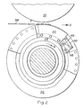
- the apparatus shown in Figure 2 comprises a cutting cylinder 30 and an impression cylinder 32 and the blank or web 34 is fed through the nip therebetween generally in the direction of the arrow A in the figures.
- the means for trapping the front edge scrap is more particularly described with reference to Figures 4 to 9, but in general it comprises a series of spring fingers 36 as in Figure 3 attached to a plate 38 in any of a plurality of positions across the plate and also in selected positions of adjustement by means of slots in the fingers through which anchor pins project.
- Spring clips 40 fix the fingers to the pins.
- Attachment holes 42 are provided in a regular series along the length of said plates.
- the plate 38 is arranged to be moved generally in the direction of the arrow B in Figure 2, and in the reverse direction, by a cam 44 provided on the impression cylinder with a cam follower 46 driving a bell crank 48 connected by a link 50 to displace the flank plate 52 carrying said plate 38.
- the impression cylinder 32 is provided with a first plate 54 of which the trailing edge (in the direction of movement of the impression cylinder B) forms an abutment for the most advanced part of the leading edge of the blank. It will be appreciated that the impression cylinder is in timed relation to the cutting cylinder.
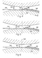
- the cam commences displacement of the plate 38 and this continues in the Figure 6 position so that the spring fingers engage on the front edge scrap.
- the cutting rule 60 which is to sever the front edge scrap from the blank, engages the blank, the cut actually being completed when the cutting rule passes through the vertical plane represented by the chain dot line 62.
- Figure 7 shows the position when the cutting rule has passed through that vertical plane and the front edge scrap separated from the blank, so that the blank continues being fed onwardly in the arrow A direction whilst the scrap is trapped between the spring fingers and the treatment roll and continues being angularly displaced about the rotational axis of the treatment roll, and hence begins to be displaced out of the plane of feed of the blank or web.
- Figures 8 and 9 show positions about 90° removed from Figure 7, when the front edge scrap is now in a plane generally at right angles to that of feed of the web or blank, this position being dictated by the configuration of the cam track.
- the spring fingers are forwardly displaced from the Figure 8 position to the Figure 9 position, thus being disengaged from the scrap piece as they pass from the scrap piece to the first plate 54, thus releasing the scrap piece so that it can fall or be drawn for example by a current of air, to a scrap conveyor for removal.
Landscapes
- Life Sciences & Earth Sciences (AREA)
- Forests & Forestry (AREA)
- Engineering & Computer Science (AREA)
- Mechanical Engineering (AREA)
- Details Of Cutting Devices (AREA)
- Perforating, Stamping-Out Or Severing By Means Other Than Cutting (AREA)
Applications Claiming Priority (2)
| Application Number | Priority Date | Filing Date | Title |
|---|---|---|---|
| GB8202402 | 1982-01-28 | ||
| GB8202402 | 1982-01-28 |
Publications (2)
| Publication Number | Publication Date |
|---|---|
| EP0085485A2 true EP0085485A2 (de) | 1983-08-10 |
| EP0085485A3 EP0085485A3 (de) | 1986-07-02 |
Family
ID=10527932
Family Applications (1)
| Application Number | Title | Priority Date | Filing Date |
|---|---|---|---|
| EP83300133A Withdrawn EP0085485A3 (de) | 1982-01-28 | 1983-01-14 | Drehende Vorrichtung zum Schneiden von Zuschnitten mit Greifer für den Abfall |
Country Status (1)
| Country | Link |
|---|---|
| EP (1) | EP0085485A3 (de) |
Family Cites Families (8)
| Publication number | Priority date | Publication date | Assignee | Title |
|---|---|---|---|---|
| US2318953A (en) * | 1942-08-05 | 1943-05-11 | Cottrell C B & Sons Co | Sheet and signature handling mechanism |
| FR1066047A (fr) * | 1950-09-04 | 1954-06-01 | Dispositif d'évacuation de feuillets séparés de poinçonnage dans les machines à poinçonner | |
| US2800078A (en) * | 1955-01-31 | 1957-07-23 | Lightbourn Salvador | Feed guide for printing equipment |
| US3008364A (en) * | 1956-05-25 | 1961-11-14 | Western Publishing Company Inc | Rotary type sheet cutter |
| US3270602A (en) * | 1964-01-28 | 1966-09-06 | Kirby S Engincers Ltd | Apparatus for cutting cardboard and analogous flexible material |
| US3410183A (en) * | 1965-11-26 | 1968-11-12 | Harris Intertype Corp | Material processing method and apparatus |
| US3643553A (en) * | 1969-10-16 | 1972-02-22 | Hideo Morimoto | Strip machine |
| US3999454A (en) * | 1975-10-20 | 1976-12-28 | George Hantscho Company, Inc. | Pinless feeder |
-
1983
- 1983-01-14 EP EP83300133A patent/EP0085485A3/de not_active Withdrawn
Also Published As
| Publication number | Publication date |
|---|---|
| EP0085485A3 (de) | 1986-07-02 |
Similar Documents
| Publication | Publication Date | Title |
|---|---|---|
| EP0146158A1 (de) | Trenneinrichtung für eine automatische Stanzmaschine | |
| US3758102A (en) | Signature cutting and trimming apparatus | |
| US6273411B1 (en) | Booklet forming method and apparatus | |
| US3811350A (en) | Sheet material trimming method and apparatus | |
| RU2243885C2 (ru) | Способ резки ценных бумаг | |
| SE441424B (sv) | Anordning for avlegsnande av avsnitt ur plana material | |
| JPH081589A (ja) | 板状加工物を打ち抜く機械の廃棄物剥取りステーション | |
| EP0390862A1 (de) | Vorrichtung zum erniedrigen der geschwindigkeit von kartongbögen | |
| US4381107A (en) | Cutting and collating method and apparatus for tickets | |
| US5921538A (en) | Apparatus and method for combined gathering and binding of sheet like articles | |
| US4466603A (en) | Methods and apparatus for producing stacks of sheets | |
| WO2013117983A2 (en) | Device for forming book blocks with two by two glued internal pages and method for formation thereof | |
| CA1088704A (en) | Combination web tucker and knife with web grippers and anvil | |
| US3524364A (en) | Apparatus for stripping waste from cardboard and like blanks | |
| US4026199A (en) | Sheet end cutter and stripper | |
| EP0036701B1 (de) | Vorrichtung zum Entfernen des Stanzabfalls | |
| JPS5911440B2 (ja) | ロ−タリダイカツタ− | |
| US4501180A (en) | Rotary die-cutting | |
| US4467948A (en) | Waste stripper | |
| US20050206066A1 (en) | Feeder for a punching of embossing apparatus and method of operating the apparatus | |
| CN108750775B (zh) | 纸张自动分叠机的分纸装置 | |
| EP0132938A1 (de) | Vorrichtung zum Rotationsformschneiden und zum Abstreifen der Abfallstücke | |
| US3370843A (en) | Method and apparatus for producing printed publications | |
| SE442967B (sv) | Sett att tillverka dubbelwell | |
| JP4068836B2 (ja) | 折り畳み前剣状部材挿入装置および方法 |
Legal Events
| Date | Code | Title | Description |
|---|---|---|---|
| PUAI | Public reference made under article 153(3) epc to a published international application that has entered the european phase |
Free format text: ORIGINAL CODE: 0009012 |
|
| AK | Designated contracting states |
Designated state(s): CH DE FR GB IT LI |
|
| RAP1 | Party data changed (applicant data changed or rights of an application transferred) |
Owner name: DEC (REALISATIONS) LIMITED |
|
| PUAL | Search report despatched |
Free format text: ORIGINAL CODE: 0009013 |
|
| AK | Designated contracting states |
Kind code of ref document: A3 Designated state(s): CH DE FR GB IT LI |
|
| STAA | Information on the status of an ep patent application or granted ep patent |
Free format text: STATUS: THE APPLICATION IS DEEMED TO BE WITHDRAWN |
|
| 18D | Application deemed to be withdrawn |
Effective date: 19870303 |
|
| RIN1 | Information on inventor provided before grant (corrected) |
Inventor name: BISHOP, DAVID JOHN GARFIELD Inventor name: BISHOP, THOMAS DESMOND |