EP0146158A1 - Trenneinrichtung für eine automatische Stanzmaschine - Google Patents
Trenneinrichtung für eine automatische Stanzmaschine Download PDFInfo
- Publication number
- EP0146158A1 EP0146158A1 EP19840201617 EP84201617A EP0146158A1 EP 0146158 A1 EP0146158 A1 EP 0146158A1 EP 19840201617 EP19840201617 EP 19840201617 EP 84201617 A EP84201617 A EP 84201617A EP 0146158 A1 EP0146158 A1 EP 0146158A1
- Authority
- EP
- European Patent Office
- Prior art keywords
- separating device
- waste
- die
- section
- female die
- Prior art date
- Legal status (The legal status is an assumption and is not a legal conclusion. Google has not performed a legal analysis and makes no representation as to the accuracy of the status listed.)
- Granted
Links
- 239000002699 waste material Substances 0.000 claims abstract description 76
- 230000000717 retained effect Effects 0.000 description 3
- 238000004519 manufacturing process Methods 0.000 description 2
- 230000002093 peripheral effect Effects 0.000 description 2
- 101150039167 Bex3 gene Proteins 0.000 description 1
- 239000011230 binding agent Substances 0.000 description 1
- 230000005484 gravity Effects 0.000 description 1
- 239000000463 material Substances 0.000 description 1
- 239000002184 metal Substances 0.000 description 1
Images


Classifications
-
- B—PERFORMING OPERATIONS; TRANSPORTING
- B26—HAND CUTTING TOOLS; CUTTING; SEVERING
- B26D—CUTTING; DETAILS COMMON TO MACHINES FOR PERFORATING, PUNCHING, CUTTING-OUT, STAMPING-OUT OR SEVERING
- B26D7/00—Details of apparatus for cutting, cutting-out, stamping-out, punching, perforating, or severing by means other than cutting
- B26D7/18—Means for removing cut-out material or waste
- B26D7/1818—Means for removing cut-out material or waste by pushing out
-
- B—PERFORMING OPERATIONS; TRANSPORTING
- B26—HAND CUTTING TOOLS; CUTTING; SEVERING
- B26F—PERFORATING; PUNCHING; CUTTING-OUT; STAMPING-OUT; SEVERING BY MEANS OTHER THAN CUTTING
- B26F1/00—Perforating; Punching; Cutting-out; Stamping-out; Apparatus therefor
- B26F1/38—Cutting-out; Stamping-out
- B26F1/40—Cutting-out; Stamping-out using a press, e.g. of the ram type
-
- Y—GENERAL TAGGING OF NEW TECHNOLOGICAL DEVELOPMENTS; GENERAL TAGGING OF CROSS-SECTIONAL TECHNOLOGIES SPANNING OVER SEVERAL SECTIONS OF THE IPC; TECHNICAL SUBJECTS COVERED BY FORMER USPC CROSS-REFERENCE ART COLLECTIONS [XRACs] AND DIGESTS
- Y10—TECHNICAL SUBJECTS COVERED BY FORMER USPC
- Y10T—TECHNICAL SUBJECTS COVERED BY FORMER US CLASSIFICATION
- Y10T225/00—Severing by tearing or breaking
- Y10T225/30—Breaking or tearing apparatus
- Y10T225/329—Plural breakers
-
- Y—GENERAL TAGGING OF NEW TECHNOLOGICAL DEVELOPMENTS; GENERAL TAGGING OF CROSS-SECTIONAL TECHNOLOGIES SPANNING OVER SEVERAL SECTIONS OF THE IPC; TECHNICAL SUBJECTS COVERED BY FORMER USPC CROSS-REFERENCE ART COLLECTIONS [XRACs] AND DIGESTS
- Y10—TECHNICAL SUBJECTS COVERED BY FORMER USPC
- Y10T—TECHNICAL SUBJECTS COVERED BY FORMER US CLASSIFICATION
- Y10T83/00—Cutting
- Y10T83/869—Means to drive or to guide tool
- Y10T83/8821—With simple rectilinear reciprocating motion only
- Y10T83/8828—Plural tools with same drive means
- Y10T83/8831—Plural distinct cutting edges on same support
-
- Y—GENERAL TAGGING OF NEW TECHNOLOGICAL DEVELOPMENTS; GENERAL TAGGING OF CROSS-SECTIONAL TECHNOLOGIES SPANNING OVER SEVERAL SECTIONS OF THE IPC; TECHNICAL SUBJECTS COVERED BY FORMER USPC CROSS-REFERENCE ART COLLECTIONS [XRACs] AND DIGESTS
- Y10—TECHNICAL SUBJECTS COVERED BY FORMER USPC
- Y10T—TECHNICAL SUBJECTS COVERED BY FORMER US CLASSIFICATION
- Y10T83/00—Cutting
- Y10T83/929—Tool or tool with support
- Y10T83/9411—Cutting couple type
- Y10T83/9423—Punching tool
- Y10T83/9428—Shear-type male tool
-
- Y—GENERAL TAGGING OF NEW TECHNOLOGICAL DEVELOPMENTS; GENERAL TAGGING OF CROSS-SECTIONAL TECHNOLOGIES SPANNING OVER SEVERAL SECTIONS OF THE IPC; TECHNICAL SUBJECTS COVERED BY FORMER USPC CROSS-REFERENCE ART COLLECTIONS [XRACs] AND DIGESTS
- Y10—TECHNICAL SUBJECTS COVERED BY FORMER USPC
- Y10T—TECHNICAL SUBJECTS COVERED BY FORMER US CLASSIFICATION
- Y10T83/00—Cutting
- Y10T83/929—Tool or tool with support
- Y10T83/9411—Cutting couple type
- Y10T83/9423—Punching tool
- Y10T83/9437—Shear-type female tool
Definitions
- the present invention relates to a separating device in an automatic stamping machine (commercially known as Cutter-Creaser), and more particularly, to a separating device in an automatic stamping machine for separating stamped paper sheet into a shaped section or sections and a waste section and smoothly removing the waste section remaining on a lower die of the separating device.
- Cutter-Creaser commercially known as Cutter-Creaser
- paper products such as corrugated cardboard boxes are manufactured by stamping a paper sheet into paper pieces of specific shape by means of an automatic stamping machine, and then folding the stamped paper pieces.
- the separating device 6 includes a lower die (not shown) for supporting the waste section 5 and an upper die 9 for pressing the shaped section 4, a stamping hole (not shown) in the lower die and a pressing portion 9a of the upper die 9 consisting of an array of a large number of pins are formed so as to have nearly the same shape and the same size as the shaped section 4, and the paper sheet 1 which has been conveyed along the upper surface of the lower jie up to the position where the shaped section 4 is registered N ith the stamping hole of the lower die, is pressed by the pressing portion 9a of the upper die 9, so that the shaped section 4 is made to fall through the stamping hole and is thus separated from the waste section 5.
- pin registering operations each time the shape of the products is changed, mounting and dismounting operations for the pins on the upper die (hereinafter called “pin registering operations") must be carried out.
- the number of the pins is large and the pins must be disposed precisely along the contour of the shaped products, and so, the operations are troublesome and necessitate a long time. Therefore, the operation of the machine must be interrupted for a long period and nence a working efficiency of the machine is bad. 4oreover, in the case where the number of products having the same shape is small,a number of times of use of each apper die and each lower die is also small and hence the operations are economically unprofitable.
- the shaped section 4 falls nearly in a horizontal attitude while being subjected to a resistance of air and is accumulated in the accumulating device 7 through the stamping hole of the lower die after it has been separated from the waste section 5, the edges 4a of the respective shaped sections 4 become misaligned, and so, the accumulated shaped sections 4 are inconvenient in handling. Especially, in the case of small-sized shaped sections 4, the above-mentioned disadvantage is remarkable.
- the waste section 5 is a portion to be thrown away, from a view point of effective utilization of the paper sheet,the waste section 5 is designed to have a minimum area, and especially a trailing edge portion of the waste section 5 is small in area and hence has a weak rigidity. Accordingly, if the waste section 5 on a lower die 10 of the separating device 6 is moved towards the belt conveyor 8 while holding up the front end poriton of the waste section 5 by means of a nipping device (not shown) as shown in Fig. 9, then the rear end portion of the waste section is bent by its own weight and thus changes from the state 5A in Fig. 9 to the state 58, so that the central part of the rear end portion will be caught by a thick portion 10a of the lower die at its center.
- Another object of the present invention is to provide a separating device in an automatic stamping machine, in which misalignment of edges of shaped sections accumulated within an accumulating device can be eliminated.
- Still another object of the present invention is to provide a separating device in an automatic stamping machine, in which a waste section remaining on a lower die of the separating device can be smoothly removed.
- a separating device in an automatic stamping machine in which a male die of the separating device and a female die adapted to fit around the male die are simultaneously formed of a single flat plate, a paper sheet fed onto the female die after having been stamped by a stamping device into a shaped section and a waste section with connecting portions retained therebetween, has its shaped section separated by pressing the shaped section with the male die, the separated shaped section is nade to fall along guide plates on the lower peripheral surface of the female die, cutting slits are formed in the waste section by waste tail cutting blades provided in a passageway of the waste section, and the waste section is severed along the cutting slits by a waste tail separating device provided at a rear portion of the female die and is thereby removed from the top of the female die.
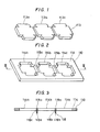
- a single plane plate 110 such as, for example, a veneer is cut by means of a laser beam so as to conform to a shape of a shaped section 112 of a paper sheet 111 to be stamped, and thereby a male die 113 and a female die 114 are simultaneously formed.
- This male die 113 consists of three male die portions 113a, 113b and 113c
- the female die 114 includes three female die portions 114a, 114b and 114c
- the respective female die portions 114a, 114b and 114c are partitioned by boundary portions 115a and 115b therebetween, and on the lower surfaces of these boundary portions 115a and 115b are provided guide plates 116.
- the guide plates 116a and 116b at the boundary portions 115a and 115b, respectively, are formed of metal plates such as, for example, nicking blades which are used for nicking folds simultaneously with a stamping operation, and they are fixedly secured onto the lower surfaces of the boundary portions 115a and 115b by means of a binder 116c.
- These guide plates 116 could be provided on a part on a whole of the peripheral portion of the female die.
- Fig. 4 shown the state where the above-described male die 113 and female die 114 have been mounted to a separating device 126 in an automatic stamping machine.
- reference numeral 117 designates a mounting table for the female die 114
- numeral 118 designates a conveying device associated with a nipping device for the paper sheet 111
- numeral 119 designates an accumulating device for the shaped sections 112
- numeral 120 designates a waste section of the paper sheet 111
- numeral 121 designates a mounting table for the male die 113
- numeral 122 designates a cam mechanism for vertically reciprocating the mounting table 121.
- the mounting table 121 is lowered by the actuation of the cam mechanism 122, so that the male die portions 113a, 113b and 113c fixedly secured to the mounting table 121 strike against the shaped sections 112a, 112b and 112c, respectively, of the paper sheet 111 and these shaped sections 112 are made to fall through the female die portions 114a, 114b and 114c, respectively.
- These guide plates 116a and 116b also serve to reinforce the boundary portions 115a and 115b of the female die 114 which portions are formed thin for the purpose of precluding waste of materials and to thereby prevent rupture of the female die 114.
- the waste section 120 left on the female die 114 is conveyed to a waste receiver (not shown) by means of a conveying device.
- a male die and a female die are simultaneously formed of a single flat plate, a die for pressing a shaped section or sections and a die for supporting a waste section can be manufactured at the same time, and moreover, since a cheap flat plate such a veneer is employed, the manufacture of the male and female dies can be achieved easily and less expensively.
- a replacement work for the dies also can be carried out easily in a short period of time as compared to the case where replacement of the dies is effected including a registering work for a large number of pins, provided that various combinations of a male die and a female die have been preliminarily prepared in the above-described manner.
- the guide plates are provided in at least one part of the lower surface of the periphery of the female die, shaped sections falling through the female die can fall right below along the guide plates. Accordingly, the respective shaped sections accumulated in the accumulating device have their edges always aligned, and hence an operation for aligning the edges of the accumulated shaped sections is unnecessary.
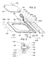
- Fig. 5 shows a separating device 126, in which reference numeral 127 designates a lower die consisting of a female die formed of a single flat plate in the above-described manner, and a workpiece such as, for example, a waste section 128 of a paper sheet is placed on the lower die 127.
- a leading end portion 129 of this waste section 128 is nipped by a paper 'sheet conveying device 149 having nipping devices, and on the opposite side regions 131 and 132 of the rear portion 130 of the waste section 128 are formed cutting slits 131a and 132a, respectively, directed in perpendicular to the traveling direction of the nipping device.
- a waste tail separating device 133 Above the rear portion 130 of the waste section 128, that is, above the rear portion 127a of the lower die 127 is disposed a waste tail separating device 133.
- a shaft 134 In this waste tail separating device 133, as shown in Figs. 5 and 6, three rollers 135 are provided at an equal interval on a shaft 134, one end of which is coupled to an electric motor 137 via a belt 136, and further the shaft 134 is connected to a bracket 139 by the intermediary of a vertically swingable lever 138.
- reference numeral 140 designates a support table for one end of a spring 141 which engages at the other end with the lever 138
- numeral 142 designates a cam
- numeral 143 designates a rod making contact with the cam 142 at one end and engaged with the lever 138 at the other end.
- Fig. 7 shows an essential part of a stamping device 150, in which a blade table 145 that is movable in the directions of arrows A145 is provided above a stamping table 144, cutting blades 146 are provided on the lower surface of the blade table 145, and waste tail cutting blades 147 are provided in the rear portion of the same lower surface.
- a paper sheet 148 fed to the stamping device 150 has cutting slits between a shaped section and a waste section formed by the cutting blades 146, and at the same time, cutting slits 131a and 132a are formed in the opposite side regions 131 and 132 of the rear portion 130 of the waste section by the waste tail cutting blades 147.
- This paper sheet 148 is moved in the direction indicated by arrow A149 as nipped by the nipping devices 149, and when the paper sheet 148 has been fed to a predetermined position in the separating device 126, the upper die 151 is abruptly lowered so as to apply an impact to the paper sheet 148 on the lower die 127 for pushing out the shaped section and making it fall into an accumulating device (not shown), so that only the waste section 128 is left on the lower die 127.
- the roller 135 in the waste tail separating device 133 is continuously rotated in the direction of arrow A135 by the motor 137, but on the other hand, the cam 142 is rotated in the direction of arrow A142, hence when the rod 143 comes into a recess 142a on the contour of the cam 142, the lever 138 is urged downwardly by the spring 141, so that the rollers 135 are transferred from the state 135a shown by phantom lines to the state 135 shown by solid lines, and act to move the waste tail 130 in the direction of arrow A130 while downwardly pressing the tail 130 of the waste section 127.
- the rod 143 which has been held in the recess 142a of the contour of the cam 142 by that time, moves onto the ridge 142b of the contour of the cam 142 as a result of rotation of the cam 142 in the direction of arrow A142, and pushes up the lever 138, so that the rollers 135 are transferred from the state 135 shown by solid lines to the state 135a shown by phantom lines, that is, the rollers 135 are raised above the rear end portion of the lower die 127.
- the present invention should not be limited to the above-described embodiments, but, for instance, the waste tail cutting blades could be provided on the upper die 151 of the separating device 126 as shown by chain lines 152 in Fig. 5 instead of being provided in the stamping device.
- waste tail cutting blades are provided in the passageway of the waste section nipped by a nipping device and a waste tail separating device is provided at the rear portion of the lower die of the separating device, it is possible that cutting slits are formed in the rear portion of the waste section, the waste tail is pulled in the opposite direction to the traveling direction of the nipping device, thus the waste section is severed at the cutting slits by pulling it at its opposite ends in the opposite directions to each other, and the respective severed parts of the waste section are moved in the opposite directions to each other.
- the waste tail is moved to the behind of the lower die, and so, the waste tail can be removed smoothly from the top of the lower die without being caught by a thick portion at the center of the lower die.
Landscapes
- Life Sciences & Earth Sciences (AREA)
- Forests & Forestry (AREA)
- Engineering & Computer Science (AREA)
- Mechanical Engineering (AREA)
- Perforating, Stamping-Out Or Severing By Means Other Than Cutting (AREA)
- Details Of Cutting Devices (AREA)
Applications Claiming Priority (4)
| Application Number | Priority Date | Filing Date | Title |
|---|---|---|---|
| JP21691683A JPS60108299A (ja) | 1983-11-17 | 1983-11-17 | 自動打抜機の分離装置 |
| JP216916/83 | 1983-11-17 | ||
| JP136234/84 | 1984-06-30 | ||
| JP13623484A JPS6114897A (ja) | 1984-06-30 | 1984-06-30 | 自動打抜機のくず分離装置 |
Publications (2)
| Publication Number | Publication Date |
|---|---|
| EP0146158A1 true EP0146158A1 (de) | 1985-06-26 |
| EP0146158B1 EP0146158B1 (de) | 1989-01-25 |
Family
ID=26469862
Family Applications (1)
| Application Number | Title | Priority Date | Filing Date |
|---|---|---|---|
| EP19840201617 Expired EP0146158B1 (de) | 1983-11-17 | 1984-11-08 | Trenneinrichtung für eine automatische Stanzmaschine |
Country Status (3)
| Country | Link |
|---|---|
| US (1) | US4921154A (de) |
| EP (1) | EP0146158B1 (de) |
| DE (1) | DE3476350D1 (de) |
Cited By (7)
| Publication number | Priority date | Publication date | Assignee | Title |
|---|---|---|---|---|
| WO1990006838A1 (fr) * | 1988-12-20 | 1990-06-28 | Bobst S.A. | Dispositif pour le decoupage et la separation de feuilles en papier, carton ou matieres semblables |
| EP0376274A3 (de) * | 1988-12-27 | 1992-01-29 | Hideo Morimoto | Verfahren und Vorrichtung zum Trennen von Abfall und Produkt |
| EP0641632A3 (de) * | 1993-09-03 | 1995-06-28 | Nippon Die Steel Kk | Ausbrechwerkzeug für Stanzmaschinen zur Herstellung von Kartonagezuschnitten. |
| BE1010305A3 (fr) * | 1996-06-27 | 1998-05-05 | Aprisys S A | Outil inferieur d'un separateur de poses dans une machine de travail d'elements en plaques ou en feuilles. |
| CN102941276A (zh) * | 2012-11-19 | 2013-02-27 | 华一精密机械(昆山)有限公司 | 异形冲头式废料防跳模具 |
| CN107030757A (zh) * | 2017-04-28 | 2017-08-11 | 浙江飞达机械有限公司 | 一种纸张冲切机 |
| US20230069199A1 (en) * | 2020-05-18 | 2023-03-02 | Koenig & Bauer Ag | Device and method for separating blanks |
Families Citing this family (33)
| Publication number | Priority date | Publication date | Assignee | Title |
|---|---|---|---|---|
| US5322202A (en) * | 1992-05-29 | 1994-06-21 | J. R. Cole Industries, Inc. | Label pressing apparatus |
| US5337639A (en) * | 1992-06-16 | 1994-08-16 | Die-X Tooling Systems | Outfeed lifter ramp for blanking boxes and other die-cut paper products |
| GB9307211D0 (en) * | 1993-04-06 | 1993-05-26 | Mead Corp | Improvements in carton blanking units |
| US5676032A (en) * | 1995-10-20 | 1997-10-14 | Southwest Die Corporation | Steel rule die with closely nested cavities |
| US5983766A (en) * | 1997-10-14 | 1999-11-16 | Johnson; Michael J. | Steel rule cutting die with removable cutting units and method for using same |
| US6308604B2 (en) | 1998-06-18 | 2001-10-30 | Genentech, Inc. | Apparatus for splitting articles |
| CA2259785C (en) | 1999-01-19 | 2008-07-29 | Peter E. Sandford | Jogger member, system and method for mounting jogger members and female and male blanking dies provided therewith |
| US6517298B1 (en) * | 1999-05-24 | 2003-02-11 | Gerber Scientific Products, Inc. | Method for selectively relieving sharp edges in tools used in die cutting sheet-type work material |
| US6408729B1 (en) | 1999-08-18 | 2002-06-25 | Michael J. Johnson | Steel rule for scrap material ejection die |
| US6658978B1 (en) | 1999-10-15 | 2003-12-09 | Ontario Die International Inc. | Steel rule die with removable cutting units |
| US6467382B2 (en) * | 2000-02-07 | 2002-10-22 | Spartanics | Extractor for extracting cut partially cut parts from a sheet of material |
| US7954407B1 (en) * | 2000-05-30 | 2011-06-07 | Jenkins Henry H | Steel rule die and steel rule |
| EP1184143A3 (de) * | 2000-08-31 | 2003-12-03 | Hallmark Cards, Incorporated | Presse zur Entfernung von Ausbrechteilen |
| DE60115702T2 (de) * | 2000-11-01 | 2006-09-07 | Carton Craft Supply, Inc. | Ausziehführung |
| US6659927B2 (en) | 2001-04-30 | 2003-12-09 | Sdc Innovations, Inc. | Folding presser assembly |
| US6692425B2 (en) * | 2001-04-30 | 2004-02-17 | Sdc Innovations, Inc. | Folding presser assembly |
| GB2377402B (en) * | 2001-07-12 | 2004-05-12 | Agilent Technologies Inc | Improved diebond strip |
| US6966873B2 (en) * | 2001-12-26 | 2005-11-22 | Blanking Systems, Inc. | Flush mounted presser assembly |
| ATE446170T1 (de) * | 2002-06-04 | 2009-11-15 | Bobst Sa | Vorrichtung zur trennung befestigungspunkte, die gestapelte kartonbogen verbinden |
| CA2458309A1 (en) * | 2003-12-01 | 2005-06-01 | Ontario Die International Inc. | Punch for a braced die |
| US20070138699A1 (en) * | 2005-12-21 | 2007-06-21 | Asml Netherlands B.V. | Imprint lithography |
| US20070163413A1 (en) * | 2006-01-18 | 2007-07-19 | John Salusbury | Steel rule die and metal sectional counter |
| DE102007040472A1 (de) * | 2007-08-28 | 2009-03-05 | Bernd Hansen | Trennvorrichtung |
| US9038511B2 (en) | 2008-11-12 | 2015-05-26 | Esko-Graphics Kongsberg As | Automatically removing waste material using a strip die when cutting a sheet of material according to a predetermined pattern |
| US8770103B2 (en) * | 2009-12-08 | 2014-07-08 | Blanking Systems, Inc. | Presser assembly having a presser and an improved mounting arrangement for mounting a pressing member to the presser |
| US8777828B2 (en) * | 2010-05-17 | 2014-07-15 | Highcon Systems Ltd. | Method and system for creating co-layer surface adhesive rule |
| US8337376B2 (en) * | 2010-08-13 | 2012-12-25 | Tian-Sheng Liu | Post-press apparatus and a method to accomplish hot foil stamping, die-cutting and blank separation in a single pass |
| EP3736057A1 (de) * | 2019-05-08 | 2020-11-11 | Koninklijke Philips N.V. | Verfahren zum formen von zähnen eines schneidmessers oder eines schutzes |
| DE102019130862B3 (de) * | 2019-11-15 | 2021-02-18 | Koenig & Bauer Ag | Bogenbearbeitungsmaschine und Verfahren zum Antreiben zumindest eines Werkzeugs einer Bogenbearbeitungsmaschine |
| CN112936983A (zh) * | 2021-02-01 | 2021-06-11 | 陕西昱升印务有限公司 | 一种自动模切系统 |
| CN113894859B (zh) * | 2021-10-15 | 2022-12-02 | 盐城工学院 | 一种汽车吸音棉封边裁切一体化装置 |
| US12257805B2 (en) | 2023-01-18 | 2025-03-25 | Blanking Systems, Inc. | Spot presser assembly |
| US12194706B2 (en) | 2023-02-03 | 2025-01-14 | Blanking Systems, Inc. | Presser assembly with magnetic biasing |
Citations (3)
| Publication number | Priority date | Publication date | Assignee | Title |
|---|---|---|---|---|
| DE1044579B (de) * | 1955-04-06 | 1958-11-20 | Goetz Heidelberg Dipl Phys | Verfahren und Vorrichtung zum Ausbrechen und Trennen von Nutzen und Abfall in gestanzten Boegen aus Karton |
| DE2535452A1 (de) * | 1975-08-08 | 1977-02-10 | Wupa Maschf Gmbh & Co | Verfahren und vorrichtung zum ausbrechen vorgestanzter materialstuecke aus bogenfoermigen materialbahnen |
| DE2542412A1 (de) * | 1975-09-23 | 1977-03-24 | Dainippon Printing Co Ltd | Vorrichtung zum kontinuierlichen ausdruecken blattfoermiger teilbereiche aus flachbaendern |
Family Cites Families (10)
| Publication number | Priority date | Publication date | Assignee | Title |
|---|---|---|---|---|
| CH189918A (de) * | 1936-02-24 | 1937-03-31 | Anton Reiche A G | Verfahren zur Herstellung von Rahmenformen für die Schokoladeherstellung und nach diesem Verfahren hergestellte Rahmenform. |
| US2175130A (en) * | 1936-08-21 | 1939-10-03 | Sabattier Charles Feli Georges | Tube for fluid or semifluid substances |
| US2759402A (en) * | 1953-10-15 | 1956-08-21 | Howard G Hemphill | Machine for removing waste slugs from carton blanks |
| US3357322A (en) * | 1965-01-12 | 1967-12-12 | Lester D Gill | Coated box and method of making |
| US3658220A (en) * | 1970-03-11 | 1972-04-25 | Harris Intertype Corp | Carton handling mechanism |
| US3863550A (en) * | 1973-03-19 | 1975-02-04 | Chem Par Corp | Cutting and scoring die |
| US4109842A (en) * | 1975-02-13 | 1978-08-29 | Aquilla John J | Sheet stripping device |
| US4235583A (en) * | 1978-03-23 | 1980-11-25 | General Motors Corporation | Extrusion die and method for making same |
| US4371369A (en) * | 1980-04-25 | 1983-02-01 | Franklin Corrugated Design, Inc. | Automatic register system for die cutting operations |
| US4665779A (en) * | 1985-03-13 | 1987-05-19 | S.O.S. Dies, Inc. | Method for making stripping dies |
-
1984
- 1984-11-08 DE DE8484201617T patent/DE3476350D1/de not_active Expired
- 1984-11-08 EP EP19840201617 patent/EP0146158B1/de not_active Expired
-
1988
- 1988-03-28 US US07/173,872 patent/US4921154A/en not_active Expired - Fee Related
Patent Citations (3)
| Publication number | Priority date | Publication date | Assignee | Title |
|---|---|---|---|---|
| DE1044579B (de) * | 1955-04-06 | 1958-11-20 | Goetz Heidelberg Dipl Phys | Verfahren und Vorrichtung zum Ausbrechen und Trennen von Nutzen und Abfall in gestanzten Boegen aus Karton |
| DE2535452A1 (de) * | 1975-08-08 | 1977-02-10 | Wupa Maschf Gmbh & Co | Verfahren und vorrichtung zum ausbrechen vorgestanzter materialstuecke aus bogenfoermigen materialbahnen |
| DE2542412A1 (de) * | 1975-09-23 | 1977-03-24 | Dainippon Printing Co Ltd | Vorrichtung zum kontinuierlichen ausdruecken blattfoermiger teilbereiche aus flachbaendern |
Cited By (8)
| Publication number | Priority date | Publication date | Assignee | Title |
|---|---|---|---|---|
| WO1990006838A1 (fr) * | 1988-12-20 | 1990-06-28 | Bobst S.A. | Dispositif pour le decoupage et la separation de feuilles en papier, carton ou matieres semblables |
| EP0376274A3 (de) * | 1988-12-27 | 1992-01-29 | Hideo Morimoto | Verfahren und Vorrichtung zum Trennen von Abfall und Produkt |
| EP0641632A3 (de) * | 1993-09-03 | 1995-06-28 | Nippon Die Steel Kk | Ausbrechwerkzeug für Stanzmaschinen zur Herstellung von Kartonagezuschnitten. |
| BE1010305A3 (fr) * | 1996-06-27 | 1998-05-05 | Aprisys S A | Outil inferieur d'un separateur de poses dans une machine de travail d'elements en plaques ou en feuilles. |
| CN102941276A (zh) * | 2012-11-19 | 2013-02-27 | 华一精密机械(昆山)有限公司 | 异形冲头式废料防跳模具 |
| CN107030757A (zh) * | 2017-04-28 | 2017-08-11 | 浙江飞达机械有限公司 | 一种纸张冲切机 |
| US20230069199A1 (en) * | 2020-05-18 | 2023-03-02 | Koenig & Bauer Ag | Device and method for separating blanks |
| US11745377B2 (en) * | 2020-05-18 | 2023-09-05 | Koenig & Bauer Ag | Device and method for separating blanks |
Also Published As
| Publication number | Publication date |
|---|---|
| EP0146158B1 (de) | 1989-01-25 |
| US4921154A (en) | 1990-05-01 |
| DE3476350D1 (en) | 1989-03-02 |
Similar Documents
| Publication | Publication Date | Title |
|---|---|---|
| EP0146158B1 (de) | Trenneinrichtung für eine automatische Stanzmaschine | |
| US7896329B2 (en) | Waste blower for a paper sheet punching and embossing machine | |
| US4612006A (en) | Die cutting apparatus | |
| US5154689A (en) | Blank forming machine with a front waste removal device | |
| JPS5911440B2 (ja) | ロ−タリダイカツタ− | |
| US4467948A (en) | Waste stripper | |
| EP1205387B1 (de) | Verfahren und Vorrichtung zum Überführen eines Flächengebildes, insbesondere eines Coupons | |
| JPH03500746A (ja) | 紙、厚紙又は同様な材料から成るシートをダイカットしかつ分離する装置 | |
| EP0132938A1 (de) | Vorrichtung zum Rotationsformschneiden und zum Abstreifen der Abfallstücke | |
| CA1232193A (en) | Blank separating device for die-cutting machines | |
| US4501180A (en) | Rotary die-cutting | |
| JP7626857B2 (ja) | シート処理機 | |
| JPH0346280B2 (de) | ||
| US12583143B2 (en) | Sheet processing machine | |
| JP2565532B2 (ja) | カセット用バネの製造方法 | |
| GB2099393A (en) | Attaching strip to a web | |
| CN112123866A (zh) | 一种纸板开槽分切一体机 | |
| US4043233A (en) | Method of preventing multi-sheet feeding | |
| JPH0713998Y2 (ja) | 切断装置 | |
| JP7209407B1 (ja) | 打抜き機 | |
| US20030107167A1 (en) | Gripper bar for die cutting machine | |
| JPS592047Y2 (ja) | 破断部付帯状素板の切断機構 | |
| EP0085485A2 (de) | Drehende Vorrichtung zum Schneiden von Zuschnitten mit Greifer für den Abfall | |
| JPS6085933A (ja) | 打抜き・筋目付け装置 | |
| JPS6150772B2 (de) |
Legal Events
| Date | Code | Title | Description |
|---|---|---|---|
| PUAI | Public reference made under article 153(3) epc to a published international application that has entered the european phase |
Free format text: ORIGINAL CODE: 0009012 |
|
| AK | Designated contracting states |
Designated state(s): CH DE FR GB IT LI SE |
|
| 17P | Request for examination filed |
Effective date: 19851128 |
|
| 17Q | First examination report despatched |
Effective date: 19861202 |
|
| R17C | First examination report despatched (corrected) |
Effective date: 19870611 |
|
| ITF | It: translation for a ep patent filed | ||
| GRAA | (expected) grant |
Free format text: ORIGINAL CODE: 0009210 |
|
| AK | Designated contracting states |
Kind code of ref document: B1 Designated state(s): CH DE FR GB IT LI SE |
|
| REF | Corresponds to: |
Ref document number: 3476350 Country of ref document: DE Date of ref document: 19890302 |
|
| ET | Fr: translation filed | ||
| PLBE | No opposition filed within time limit |
Free format text: ORIGINAL CODE: 0009261 |
|
| STAA | Information on the status of an ep patent application or granted ep patent |
Free format text: STATUS: NO OPPOSITION FILED WITHIN TIME LIMIT |
|
| 26N | No opposition filed | ||
| ITTA | It: last paid annual fee | ||
| EAL | Se: european patent in force in sweden |
Ref document number: 84201617.2 |
|
| PGFP | Annual fee paid to national office [announced via postgrant information from national office to epo] |
Ref country code: SE Payment date: 19950829 Year of fee payment: 12 |
|
| PGFP | Annual fee paid to national office [announced via postgrant information from national office to epo] |
Ref country code: FR Payment date: 19950918 Year of fee payment: 12 |
|
| PGFP | Annual fee paid to national office [announced via postgrant information from national office to epo] |
Ref country code: GB Payment date: 19951030 Year of fee payment: 12 |
|
| PGFP | Annual fee paid to national office [announced via postgrant information from national office to epo] |
Ref country code: CH Payment date: 19951108 Year of fee payment: 12 |
|
| PGFP | Annual fee paid to national office [announced via postgrant information from national office to epo] |
Ref country code: DE Payment date: 19951127 Year of fee payment: 12 |
|
| PG25 | Lapsed in a contracting state [announced via postgrant information from national office to epo] |
Ref country code: GB Effective date: 19961108 |
|
| PG25 | Lapsed in a contracting state [announced via postgrant information from national office to epo] |
Ref country code: SE Effective date: 19961109 |
|
| PG25 | Lapsed in a contracting state [announced via postgrant information from national office to epo] |
Ref country code: LI Effective date: 19961130 Ref country code: CH Effective date: 19961130 |
|
| GBPC | Gb: european patent ceased through non-payment of renewal fee |
Effective date: 19961108 |
|
| REG | Reference to a national code |
Ref country code: CH Ref legal event code: PL |
|
| PG25 | Lapsed in a contracting state [announced via postgrant information from national office to epo] |
Ref country code: FR Effective date: 19970731 |
|
| PG25 | Lapsed in a contracting state [announced via postgrant information from national office to epo] |
Ref country code: DE Effective date: 19970801 |
|
| EUG | Se: european patent has lapsed |
Ref document number: 84201617.2 |
|
| REG | Reference to a national code |
Ref country code: FR Ref legal event code: ST |