EP0085875A2 - Dispositif de mesure des grandeurs physiques à fibres optiques - Google Patents
Dispositif de mesure des grandeurs physiques à fibres optiques Download PDFInfo
- Publication number
- EP0085875A2 EP0085875A2 EP83100560A EP83100560A EP0085875A2 EP 0085875 A2 EP0085875 A2 EP 0085875A2 EP 83100560 A EP83100560 A EP 83100560A EP 83100560 A EP83100560 A EP 83100560A EP 0085875 A2 EP0085875 A2 EP 0085875A2
- Authority
- EP
- European Patent Office
- Prior art keywords
- light
- measuring arrangement
- luminescent
- optical
- fiber optic
- Prior art date
- Legal status (The legal status is an assumption and is not a legal conclusion. Google has not performed a legal analysis and makes no representation as to the accuracy of the status listed.)
- Withdrawn
Links
Images


Classifications
-
- G—PHYSICS
- G01—MEASURING; TESTING
- G01D—MEASURING NOT SPECIALLY ADAPTED FOR A SPECIFIC VARIABLE; ARRANGEMENTS FOR MEASURING TWO OR MORE VARIABLES NOT COVERED IN A SINGLE OTHER SUBCLASS; TARIFF METERING APPARATUS; MEASURING OR TESTING NOT OTHERWISE PROVIDED FOR
- G01D5/00—Mechanical means for transferring the output of a sensing member; Means for converting the output of a sensing member to another variable where the form or nature of the sensing member does not constrain the means for converting; Transducers not specially adapted for a specific variable
- G01D5/26—Mechanical means for transferring the output of a sensing member; Means for converting the output of a sensing member to another variable where the form or nature of the sensing member does not constrain the means for converting; Transducers not specially adapted for a specific variable characterised by optical transfer means, i.e. using infrared, visible, or ultraviolet light
- G01D5/268—Mechanical means for transferring the output of a sensing member; Means for converting the output of a sensing member to another variable where the form or nature of the sensing member does not constrain the means for converting; Transducers not specially adapted for a specific variable characterised by optical transfer means, i.e. using infrared, visible, or ultraviolet light using optical fibres
Definitions
- the invention relates to a fiber-optic measuring arrangement for measuring physical quantities according to the preamble of claim 1.
- a luminescence-based fiber-optic measuring arrangement for measuring mechanical quantities is known from DE-OS 30 47 343.
- the mechanical quantity to be measured in accordance with its changing value, causes a change in the position of a luminescent material relative to the end of an optical fiber entering the sensor.
- This type of sensor has the advantage over mechanical sensors which are based on the change in position of reflecting components that a change in wavelength takes place in the sensor, which makes it possible to use optical filters to reflect light reflected in the fiber-optic system. to be able to excrete at light emitters and / or light detectors.
- the luminescence-absorbing measuring arrangement mentioned cannot be used if high demands are placed on the accuracy and the sensor is simultaneously exposed to large temperature changes.
- the invention has for its object to develop a measuring arrangement of the type mentioned, in which high accuracy can also be achieved when the sensor is exposed to large changes in temperature.
- the invention thus provides a measurement arrangement based on luminescence which is free from the disadvantages of fiber optic measurement arrangements based on other principles on the one hand and on the other hand is practically independent of temperature changes in its measurement accuracy. Instead of measuring the relative light intensities of two luminescent elements arranged next to one another with different luminescence spectra, the invention measures a selectively excited luminescence with identical luminescence spectra, thereby eliminating the temperature dependency.
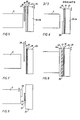
- FIG. 2 An example of the spectral relationships of the system according to FIG. 1 is shown in FIG. 2, in which the emission spectrum 25 of the light-emitting diode 2, the absorption spectra 26a, 26b of the layers 18 and 22 of the elements 15 and 16, the luminescence spectrum 27 of the layer 18, the Luminescence spectrum 28 of layer 22, the transmission spectrum 29 of filter 6 and the transmission spectrum 20 of filter 7 are shown.
- the luminescence spectra 27 and 28 are shifted in wavelength, as a result of which the function of the filter with the spectrum 29 becomes critical with regard to the accuracy of the measuring device.
- FIG. 3a shows a sensor in which the elements 15 and 16 are integrated on one and the same substrate. If, for example, liquid epitaxy is used, the layers 23, 22, 38, 19, 18 and 17 are applied in succession to the substrate 24. Then layers 17, 18 and 19 are scg. selective etchant partially etched away spatially. In an Al 1-x Ga x As structure, the layers are determined by different values for x, which gives the desired optical properties and at the same time creates the conditions for selective etching. 6 shows a somewhat simpler structure, the layers 17, 18 and 19 being common for the two sensor elements.
- the layer 38 is etched away on the upper sensor element in the figure, as a result of which it luminesces both with excitation light from the light-emitting diode 2 and with excitation light from the light-emitting diode 31.
- the lower sensor element on the other hand, only luminesces with excitation light from the light-emitting diode 31.
- the layer 38 serves as a filter which is selective for the light sources 2 and 31 and can, as shown in FIG. 7, be detached from the luminescent element, the filter 38 in vertical direction depending on the measured variable between the fiber 5 and the luminescent layer 18 is shifted.
- the layer 18 can be etched out using lithography that a grid according to FIG. 8 is created.
- a grid 45 must be present on a transparent substrate 44 at the end of the fiber.
- better reproducibility is also obtained by modulating simultaneously over the entire sensor area, so that local defects cannot have any significant disturbing influence.
- part of the luminescent layer 18 can be etched away as shown in FIG. 9. This gives you better options for achieving a linear encoder characteristic.
- the arrangements described above can be varied in many ways within the scope of the general inventive concept disclosed.
Landscapes
- Physics & Mathematics (AREA)
- General Physics & Mathematics (AREA)
- Length Measuring Devices By Optical Means (AREA)
- Investigating, Analyzing Materials By Fluorescence Or Luminescence (AREA)
- Investigating Or Analysing Materials By Optical Means (AREA)
- Optical Transform (AREA)
- Spectrometry And Color Measurement (AREA)
- Light Guides In General And Applications Therefor (AREA)
Applications Claiming Priority (2)
| Application Number | Priority Date | Filing Date | Title |
|---|---|---|---|
| SE8200575 | 1982-02-02 | ||
| SE8200575A SE435966B (sv) | 1982-02-02 | 1982-02-02 | Fiberoptiskt metdon |
Publications (2)
| Publication Number | Publication Date |
|---|---|
| EP0085875A2 true EP0085875A2 (fr) | 1983-08-17 |
| EP0085875A3 EP0085875A3 (fr) | 1986-09-17 |
Family
ID=20345891
Family Applications (1)
| Application Number | Title | Priority Date | Filing Date |
|---|---|---|---|
| EP83100560A Withdrawn EP0085875A3 (fr) | 1982-02-02 | 1983-01-22 | Dispositif de mesure des grandeurs physiques à fibres optiques |
Country Status (5)
| Country | Link |
|---|---|
| US (1) | US4560868A (fr) |
| EP (1) | EP0085875A3 (fr) |
| JP (1) | JPS58137710A (fr) |
| CA (1) | CA1186525A (fr) |
| SE (1) | SE435966B (fr) |
Cited By (4)
| Publication number | Priority date | Publication date | Assignee | Title |
|---|---|---|---|---|
| EP0144630A3 (en) * | 1983-10-12 | 1985-07-10 | Luxtron Corporation | Applications of heat flux modulation of a temperature probe |
| EP0266118A1 (fr) * | 1986-10-24 | 1988-05-04 | The University Of Liverpool | Détection d'un déplacement |
| EP0216163A3 (fr) * | 1985-08-22 | 1989-01-25 | Mitsubishi Denki Kabushiki Kaisha | Appareil de mesure optique |
| EP0266539A3 (fr) * | 1986-11-07 | 1991-08-07 | International Business Machines Corporation | Interféromètre de surface |
Families Citing this family (15)
| Publication number | Priority date | Publication date | Assignee | Title |
|---|---|---|---|---|
| GB8311256D0 (en) * | 1983-04-26 | 1983-06-02 | Central Electr Generat Board | Measuring external parameter |
| JPS60200121A (ja) * | 1984-03-23 | 1985-10-09 | Mitsubishi Electric Corp | 光応用計測装置 |
| US4683374A (en) * | 1985-08-07 | 1987-07-28 | General Signal Corporation | Method and means for multiplexing optical sensors |
| US4701611A (en) * | 1985-09-30 | 1987-10-20 | Mechanical Technology Incorporated | Reflectivity compensated fiber optic sensor |
| US4752141A (en) * | 1985-10-25 | 1988-06-21 | Luxtron Corporation | Fiberoptic sensing of temperature and/or other physical parameters |
| GB8531149D0 (en) * | 1985-12-18 | 1986-01-29 | Smiths Industries Plc | Optical transducers |
| US4947036A (en) * | 1986-10-03 | 1990-08-07 | Conax Buffalo Corporation | Self-monitoring optical sensor having a ratiometric output signal |
| EP0288514A4 (fr) | 1986-10-03 | 1990-01-08 | Conax Buffalo Corp | Appareil de protection a fibre optique. |
| GB8909593D0 (en) * | 1989-04-26 | 1989-06-14 | Unicon Holdings Ltd | Optical fibre sensor system |
| US5177352A (en) * | 1991-06-06 | 1993-01-05 | The United States Of America As Represented By The United States Department Of Energy | Integrated optical tamper sensor with planar waveguide |
| US7043984B2 (en) * | 2004-01-13 | 2006-05-16 | Fling John J | Automatically actuated liquid level sensor |
| US7418861B2 (en) * | 2006-01-10 | 2008-09-02 | Fling John J | Mechanically self actuated liquid level sensor |
| US20070171638A1 (en) * | 2006-01-24 | 2007-07-26 | Sbc Knowledge Ventures, L.P. | Apparatus and methods for transmitting light over optical fibers |
| US7444865B2 (en) * | 2006-05-04 | 2008-11-04 | Fling John J | Parallelogram actuated liquid level sensor |
| US20250389580A1 (en) * | 2024-06-25 | 2025-12-25 | Khalifa University of Science and Technology | 3d printed multi-material optical fiber sensor for simultaneous detection of ultraviolet radiation and temperature |
Family Cites Families (7)
| Publication number | Priority date | Publication date | Assignee | Title |
|---|---|---|---|---|
| SE415397B (sv) * | 1978-06-02 | 1980-09-29 | Asea Ab | Fiberoptiskt metdon |
| SE413555B (sv) * | 1978-09-15 | 1980-06-02 | Asea Ab | Fiberoptiskt metdon |
| SE7903175L (sv) * | 1979-04-10 | 1980-10-11 | Asea Ab | Fiberoptiskt metdon |
| SE417137B (sv) * | 1979-05-31 | 1981-02-23 | Asea Ab | Optiskt metdon for metning av magnetiska och elektriska felt |
| SE431259B (sv) * | 1979-10-10 | 1984-01-23 | Asea Ab | Fiberoptisk temperaturgivare baserad pa fotoluminiscens hos ett fast material |
| SE418904B (sv) * | 1979-12-28 | 1981-06-29 | Asea Ab | Fiberoptiskt metdon for metning av fysikaliska storheter sasom lege, hastighet, acceleration, kraft, tryck, tojning och temperatur |
| US4356396A (en) * | 1980-12-17 | 1982-10-26 | Siemens Corporation | Fiber optical measuring device with compensating properties |
-
1982
- 1982-02-02 SE SE8200575A patent/SE435966B/sv not_active IP Right Cessation
-
1983
- 1983-01-22 EP EP83100560A patent/EP0085875A3/fr not_active Withdrawn
- 1983-01-31 US US06/462,702 patent/US4560868A/en not_active Expired - Fee Related
- 1983-01-31 JP JP58014475A patent/JPS58137710A/ja active Pending
- 1983-02-01 CA CA000420708A patent/CA1186525A/fr not_active Expired
Cited By (5)
| Publication number | Priority date | Publication date | Assignee | Title |
|---|---|---|---|---|
| EP0144630A3 (en) * | 1983-10-12 | 1985-07-10 | Luxtron Corporation | Applications of heat flux modulation of a temperature probe |
| US4621929A (en) * | 1983-10-12 | 1986-11-11 | Luxtron Corporation | Fiber optic thermal anemometer |
| EP0216163A3 (fr) * | 1985-08-22 | 1989-01-25 | Mitsubishi Denki Kabushiki Kaisha | Appareil de mesure optique |
| EP0266118A1 (fr) * | 1986-10-24 | 1988-05-04 | The University Of Liverpool | Détection d'un déplacement |
| EP0266539A3 (fr) * | 1986-11-07 | 1991-08-07 | International Business Machines Corporation | Interféromètre de surface |
Also Published As
| Publication number | Publication date |
|---|---|
| SE435966B (sv) | 1984-10-29 |
| US4560868A (en) | 1985-12-24 |
| CA1186525A (fr) | 1985-05-07 |
| EP0085875A3 (fr) | 1986-09-17 |
| SE8200575L (sv) | 1983-08-03 |
| JPS58137710A (ja) | 1983-08-16 |
Similar Documents
| Publication | Publication Date | Title |
|---|---|---|
| DE3047343C2 (fr) | ||
| DE3409618A1 (de) | Faseroptische messanordnung zur messung physikalischer groessen | |
| DE3689640T2 (de) | Fiberoptischer Sensor. | |
| CH639196A5 (de) | Messgeraet zum messen von physikalischen groessen mittels optischer mittel. | |
| DE3036682C2 (fr) | ||
| EP1405037B1 (fr) | Dispositif de mesure optique de distance sur une plage de mesure etendue | |
| CH638892A5 (de) | Messgeraet zum messen von physikalischen groessen. | |
| DE3019030A1 (de) | Optisches messgeraet zur messung magnetischer und elektrischer felder | |
| EP0095998A1 (fr) | Arrangement de mesure à fibres optiques | |
| DE3101047A1 (de) | "faseroptisches messgeraet zur messung einer kraft oder eines druckes" | |
| DE2934859A1 (de) | Optisches messgeraet | |
| DE2947549A1 (de) | Faseroptisches temperaturmessgeraet | |
| DE3122788A1 (de) | "faseroptische temperaturmessanordnung" | |
| EP0291729A2 (fr) | Procédé et dispositif pour mesurer la position des fils de trame ou des rangées de mailles dans les bandes textiles | |
| DE3141448C2 (fr) | ||
| EP0509979A2 (fr) | Dispositif de mesure de positions photo-électronique | |
| DE3409207A1 (de) | Optischer sensor | |
| EP0083689B1 (fr) | Dispositif photo-électrique incrémentiel pour mesurer des longueurs ou des angles | |
| DE3215959A1 (de) | Faseroptische messanordnung | |
| EP0050306A2 (fr) | Dispositif de mesure à fibres optiques | |
| EP0379097A2 (fr) | Procédé pour déterminer la position d'un bord et capteur photoélectrique pour cette détermination | |
| EP0290789A2 (fr) | Dispositif pour la mesure de la distance entre le dispositif et une surface de mesure | |
| EP0096262B1 (fr) | Sensor à fibre optique pour mesurer des grandeurs dynamiques | |
| DE2140126A1 (de) | Optischer Komparator | |
| EP0116131A2 (fr) | Transducteur à fibres optiques |
Legal Events
| Date | Code | Title | Description |
|---|---|---|---|
| PUAI | Public reference made under article 153(3) epc to a published international application that has entered the european phase |
Free format text: ORIGINAL CODE: 0009012 |
|
| AK | Designated contracting states |
Designated state(s): CH DE FR GB LI |
|
| PUAL | Search report despatched |
Free format text: ORIGINAL CODE: 0009013 |
|
| AK | Designated contracting states |
Kind code of ref document: A3 Designated state(s): CH DE FR GB LI |
|
| 17P | Request for examination filed |
Effective date: 19870228 |
|
| STAA | Information on the status of an ep patent application or granted ep patent |
Free format text: STATUS: THE APPLICATION HAS BEEN WITHDRAWN |
|
| 18W | Application withdrawn |
Withdrawal date: 19880506 |
|
| RIN1 | Information on inventor provided before grant (corrected) |
Inventor name: BROGARDH, TORGNY Inventor name: OVREN, CHRISTER, DR. ING. Inventor name: HOEK, BERTIL, DR. PHIL. |