EP0085964A2 - Galerie - Google Patents
Galerie Download PDFInfo
- Publication number
- EP0085964A2 EP0085964A2 EP83101071A EP83101071A EP0085964A2 EP 0085964 A2 EP0085964 A2 EP 0085964A2 EP 83101071 A EP83101071 A EP 83101071A EP 83101071 A EP83101071 A EP 83101071A EP 0085964 A2 EP0085964 A2 EP 0085964A2
- Authority
- EP
- European Patent Office
- Prior art keywords
- roof rack
- support elements
- rack according
- bracket
- roof
- Prior art date
- Legal status (The legal status is an assumption and is not a legal conclusion. Google has not performed a legal analysis and makes no representation as to the accuracy of the status listed.)
- Withdrawn
Links
- 230000007704 transition Effects 0.000 claims description 3
- 239000011241 protective layer Substances 0.000 claims description 2
- 239000012858 resilient material Substances 0.000 claims description 2
- 238000000034 method Methods 0.000 description 5
- 101100498160 Mus musculus Dach1 gene Proteins 0.000 description 2
- 238000006073 displacement reaction Methods 0.000 description 2
- 230000000694 effects Effects 0.000 description 2
- 230000002349 favourable effect Effects 0.000 description 2
- 239000010410 layer Substances 0.000 description 2
- 239000000463 material Substances 0.000 description 2
- 230000006978 adaptation Effects 0.000 description 1
- 238000013475 authorization Methods 0.000 description 1
- 239000011324 bead Substances 0.000 description 1
- 230000027455 binding Effects 0.000 description 1
- 238000009739 binding Methods 0.000 description 1
- 238000010276 construction Methods 0.000 description 1
- 230000018109 developmental process Effects 0.000 description 1
- 230000012447 hatching Effects 0.000 description 1
- 238000004519 manufacturing process Methods 0.000 description 1
- 238000003825 pressing Methods 0.000 description 1
- 239000007787 solid Substances 0.000 description 1
- 238000003860 storage Methods 0.000 description 1
Images


Classifications
-
- B—PERFORMING OPERATIONS; TRANSPORTING
- B60—VEHICLES IN GENERAL
- B60R—VEHICLES, VEHICLE FITTINGS, OR VEHICLE PARTS, NOT OTHERWISE PROVIDED FOR
- B60R9/00—Supplementary fittings on vehicle exterior for carrying loads, e.g. luggage, sports gear or the like
- B60R9/04—Carriers associated with vehicle roof
- B60R9/042—Carriers characterised by means to facilitate loading or unloading of the load, e.g. rollers, tracks, or the like
-
- B—PERFORMING OPERATIONS; TRANSPORTING
- B60—VEHICLES IN GENERAL
- B60R—VEHICLES, VEHICLE FITTINGS, OR VEHICLE PARTS, NOT OTHERWISE PROVIDED FOR
- B60R9/00—Supplementary fittings on vehicle exterior for carrying loads, e.g. luggage, sports gear or the like
- B60R9/08—Supplementary fittings on vehicle exterior for carrying loads, e.g. luggage, sports gear or the like specially adapted for sports gear
Definitions
- the invention relates to a roof rack for vehicles, in particular for transporting at least one surfboard, with at least two brackets running across the roof and attachable to the gutter or the doors.
- the object of the present invention is therefore to create a roof rack in which a surfboard can be loaded and unloaded by a person even without outside help.
- This object is achieved in that on each of the brackets an element is slidably supported along the same, each carrying an articulated connection or in cooperation with elements of the bracket forms an articulated connection, around which at least one each extends over the associated bracket, in essentially elongated support element is pivotable such that it extends down the side of the vehicle when the element is displaced in the direction of the free end of the support element up to the edge of the associated bracket, and at least one of which can be locked in the outer region of the bracket when the elements are on the brackets are pushed back.
- the support elements are preferably rod-shaped mig formed and expediently have a flat surface facing upwards.
- the support elements are expediently connected to one another by at least one longitudinal strut. The arrangement becomes particularly stable if a longitudinal strut is attached to the outer edge of the support elements and at least one further longitudinal strut in the central region of the support elements.
- the stirrups are tubular, with a continuous slot on their upper area, through which at least the upper edge of the respective support element protrudes.
- Brackets have proven to be particularly favorable which are rectilinear and cylindrical in the area running over the roof and preferably have a rectangular cross section, the longitudinal slot being in each case provided on the upper side and the two edges of the longitudinal slot preferably being bent inwards.
- the support elements are designed as rods with mutually parallel side walls, which are adjacent to one of their ends in their lower region are provided with a widening, which prevents the rods in this area from being pulled upwards out of the longitudinal slots. Together with the edges of the longitudinal slots, these widenings form the articulated connections.
- the widening is expediently formed by a pin fastened to the underside of the rods, the free ends of which protrude laterally beyond the side walls of the rods on both sides.
- a pin is expediently provided which penetrates the brackets transversely.
- the undersides of the rods forming the support elements slide out on this pin when the support elements are pulled out of the brackets.
- releasable locking means are also provided, for example in the form of insertable pins or screws, which, in cooperation with the pins and the pin located on the underside of the rods at their opposite ends, limit the pivoting movement, which is sought when the Support elements should form the roof area of a tent canopy.
- An effective locking of the roof rack for the driving condition can be achieved, on the one hand, by providing a tab adjacent to the free ends of the support elements, which, when the elements are retracted, extend down to below the bracket and each have a through hole.
- the through holes are aligned and serve to receive the mast from the surfboard.
- a pin is expediently fitted in the outer region of the bracket, on which an inwardly facing, essentially horizontal slot in the tabs or an outwardly facing corresponding slot in the elements can be pushed. The assumed end positions of the displacement are thereby additionally secured.
- a simple and also theft-proof mounting of the surfboard on the roof rack is obtained if a hole is provided in at least one of the longitudinal struts, through which a screw can be passed, which can be screwed into a bolt that can be inserted into the sword box of the surfboard.
- the one with a head Bolts prevented from falling through by the sword case expediently have a polygonal cross section which prevents the bolt from being unscrewed from above. Since the distance between the roof of the vehicle and the lower edge of the screw is so small that the screw cannot be unscrewed from the bolt when the roof rack is brought into the position intended for transport, the bolt is formed in the lower area that it is spread out by screwing in the screw.
- the longitudinal strut which connects the free ends of the support elements to one another, is rotatably mounted or provided with a rotatably mounted slide tube, at least one pawl being detachably attached to the ends of these rotatable parts can be brought into engagement with an abutment on the corresponding bracket.
- Accidental displacement of the support elements or lifting at the free ends is particularly effectively prevented here if the pawl is spring-loaded in the direction of the closed position.
- At least one central rod which projects essentially perpendicularly from the longitudinal strut and is preferably detachably fastened to the longitudinal strut, serves to rotate the longitudinal strut.
- the locking device described above proves to be particularly suitable for motorhomes in which the roof rack is very high.
- This configuration further enables an extremely simple design of an awning, the central pole serving as a strut seated on the floor. Additional brackets attached to the free ends of the support elements and / or to the longitudinal strut allow the attachment of additional struts to stabilize the awning.
- the free ends of the brackets are designed so that they can be inserted into a roof gutter of the motor vehicle, hooks engaging around the gutter or edge of the door, which can be determined by a screw on the bracket, and the screw receives a bore passing through it, into which an angled rigid bracket can be inserted at one end, the other end of which is secured by inserting it between the door and door frame of the vehicle and then closing the vehicle door .
- the roof rack can also be used for the transport of skis if elements carrying joint connections are used on the brackets and the distance between the support elements and the brackets is selected so that skis can be clamped between them. It is furthermore expedient if the top of the support elements and / or the inside of the contact areas and / or the underside of the support elements or the top of the brackets are provided with an elastically flexible protective layer so that the objects carried on the roof rack are not loaded during loading or being chafed while driving. The attachment of padding to the lower edge of the straps prevents possible damage to the vehicle side wall if the roof rack is overloaded during loading or if the unloading process is carried out improperly.
- a cover is attached to the support elements and / or the longitudinal struts, which cover can consist rigidly of elastically resilient material such as hard PVC and is preferably releasably attached.
- the cover can also serve as the roof of an awning, which can be completed by attaching wall parts of an awning to the support elements and / or the longitudinal section, for example by means of zippers, push buttons or Velcro fasteners.
- the wall parts can also be designed such that they can be rolled up. The same applies to the cover.
- a roof rack 2 is fastened, on which a surfboard 3 and possibly another surfboard 4 are fastened.
- the roof rack 2 consists of two brackets 5 and 6 with a horizontal area running across the roof and downward bent end areas 7 and 8, with their free ends in the gutters 9 and 10 of the vehicle roof 1.
- Sleeves 11 and 12 are slidably supported on the brackets along the rectilinear region of the brackets 5 and 6.
- the sleeves contain a laterally occupied longitudinal slot 13.
- an upstanding projection 14, 15 is attached, which is at its front, laterally to the end of the Sleeves 11 and 12 occupy the end of a joint 16, 17 in which the ends of tubes 18 and 19, which form the support elements for the surfboard 3, are pivotally mounted.
- the tubes 18 and 19 extend parallel to the brackets 5 and 6 from the sleeves 11 and 12 to the end of the rectilinear region of the brackets, in which they merge into the end regions 7.
- the tubes carry bends 20 and 21 which protrude vertically upwards at right angles, which form vertical contact areas for the surfboard 3.
- a downwardly projecting tab 23 is fastened which, in the position assumed in FIG.
- the tabs 23 contain a through hole 24, the diameter of which corresponds to that of a mast 25 to be transported with the surfboard. If, as strength by the hatching of F. 1 indicated that in addition to the surfboard 3 an overlying surfboard 4 is to be transported, the tab 23 has a further area designated 23a, which has a further bore for receiving a second mast, which of course also, as indicated by reference number 21a, extend the side turns further up.
- the tabs 23 also contain a longitudinal slot 26 which runs parallel to the brackets 5 and 6 and which receives a pin 27 which projects rearwards in the end region of the straight part of the brackets 5 and 6.
- a hole 28 with a small diameter is made in the tabs 23, which, in the position of the roof rack 1 assumed in FIG. 1, lies opposite a longitudinal hole 29 in the bracket 5 or 6. Details of this configuration are best known 7 and 8 can be seen. It can be seen there that a bracket 30 of a lock 31 can be inserted through the bores 28 and 29 when the pin 27 assumes the end position in the longitudinal slot 26 connected pin 33 secured through a hole 34 through the mast 25. As soon as the bracket 30 is passed through the bores 28 and 29 and the end ring 32 and the lock 31 is closed, the mast can no longer be removed without authorization and the roof rack can no longer be moved out of the position shown in FIG. 1.
- the two tubes 18 and 19 serving as support elements are connected to one another approximately in the region of their center by a longitudinal strut 35 which contains a series of bores 36. These bores, together with the fastening mechanism shown in FIGS. 4 to 6, permit theft-proof mounting of the surfboard 3 on the roof rack 1.
- the fastening mechanism consists of a bolt 37 which contains flats 38 in its upper region, which are just designed so that that the bolt can be inserted into a sword case 39 of the surfboard 3, as shown in FIG. 4, with the surfboard 3 lying on the tubes 18 and 19.
- the flats 38 prevent the bolt 37 from rotating in the sword case 39.
- the bolt 37 contains longitudinal grooves 40, 41, 42 and 43 and an end flange 44. It also has an internal thread 45 in its interior.
- a screw 47 is screwed into the internal thread 45 of the bolt 37 screwed in, the E whereby nd- portion of the bolt expands, so that the flange 44 at the lower edges of the bore 36, as shown in FIG. 5 can be seen, is supported.
- the length of the screw 47 is chosen to be greater than the height h, which in FIG. 5 indicates the distance between the upper edge of the roof 1 and the lower edge of the screw in the screwed-in state. In this way it is ensured that the screw 47 can only be completely loosened when the roof rack is in the position shown in FIG. 2. This means that in the position of the roof rack shown in Fig.
- the space between the brackets 5 and 6 and the tubes 18 and 19 can, as indicated in FIGS. 1 and 3, also be used to hold skis 49 which can be clamped in between. It is advisable to provide the top of the brackets 5 and 6 and / or the underside of the tubes 18 and 19 with an elastic surface, which also compensates for certain differences in thickness. However, these elastic layers are not shown in the drawings. It goes without saying that the skis must be inserted and removed before the roof rack is transferred from the position shown in FIG. 1 to the position shown in FIG. 2, since otherwise the sleeves 11 or 12 cannot be moved undisturbed.
- the tubes 18 and 19 can be designed to be telescopically extendable, as indicated by a dot-dash line in FIG. 2.
- the tubes slide on a cylindrical rod 51 fastened in the region of the joints 16 and 17, which carries at its front end a projection 52 reaching as far as the wall of the tubes.
- a ring 53 is inserted, the central bore of which is displaceable along the rod 51.
- a weight compensation spring 54 is clamped, which is compressed during the transition of the roof rack from the position shown in FIG. 1 to the position shown in FIG. 2 and supports the lifting of the load in the reverse process.
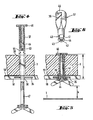
- Fig. 9 an additional security system is shown, which prevents unauthorized removal of the roof rack.
- a threaded bore 55 is provided slightly above the free end, into which a fastening screw 56 can be screwed.
- the fastening screw 56 extends loosely through a bore 57 in the upper end of a hook 58 which is supported with its upper end 59 in a bead 60 provided above the threaded bore 55 in the end region 7.
- the lower end 62 of the hook 58 engages around the gutter 9, wherein it is pressed against the fastening screw 56 by tightening it.
- a wire-shaped stiff angled bracket 63 is inserted with its upper end through a transversely through the fastening screw 56 bore 64 which with its inwardly projecting free En de between a door 65 and a door frame 66 can be inserted and clamped therein.
- the bracket 63 includes a head 67 at its upper end, which prevents the bracket from being pushed downward by force through the bore 64. It is also possible to attach an anchor 68 to the free end clamped in the area between door 65 and door frame 66, which anchor can be rotated or bent about the longitudinal axis of the bracket and additionally counteracts violent removal of the bracket 63.
- the bracket 6 is in this case divided into two tubes 6a and 6b, which are plugged together by a U-profile tube 69 inserted in both free ends.
- the tubes 6a and 6b can be brought closer to or removed from one another.
- a cover 74 is also indicated, which can be solid and serves to protect the skis in the event of transport.
- the cover 74 it is also possible to manufacture the cover 74 from an elastically flexible, possibly stretchable material and to make the cover removable.
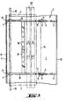
- the brackets 5, 6 here consist at least in the region running straight over the roof 1 from tubes 8 0 , which, as can be seen from the sectional view of FIG. 15, have a rectangular cross section and have continuous longitudinal slots 81 on their top, in the area of the Edge, as indicated by reference numeral 81a, is bent inwards so that it forms a guide surface.
- Straight tubes 82 are guided in the tubes 8o, which have a rectangular cross section and, as can be seen in FIG. 15, can be hollow.
- the bars 82 have two mutually parallel side walls 83 and 84 which run parallel to the longitudinal slot 81, the inwardly bent edges 81a forming a guide for the bars 82.
- the upper ends of the rods 82 protrude above the pipes 8o.
- a pin 85 is attached transversely to the longitudinal direction of the rods 82 in such a way that the free ends of the pin 85 run approximately perpendicular to the longitudinal slot 81 to close reach to the inner wall of the pipes 8o, but with so much play that when the rods 82 are pulled out from the view from FIG.
- the pin 85 prevents the rods 82 from being able to be lifted up out of the longitudinal slots 81 at their right-hand ends as seen in FIG. 16. From the point of view 16 ends of the stirrups 5, 6 through the tubes 8o each penetrate a pin 86, the upper edge of which lies in such a way that the bars 82, as indicated by dashed lines in FIG. 17, rest on their underside and slide along as they are pulled out. Above the pin 86, shifted somewhat inward relative to this, an optionally insertable locking member 87 is provided laterally to the longitudinal slot 81 in the tube 80, which can be formed by a screw or a bolt. As can be seen from FIG.
- the locking member 87 prevents the rods 82 from being able to be pulled out completely, as a result of which the maximum inclination of the rods 82 with respect to the horizontal is limited.
- This state is shown in Fig. 14 with solid lines.
- the bars 82 form the lateral boundaries for the roof of an awning formed from them, as shown in FIG. 13.
- the rods 82 can be pulled further outwards, so that, as indicated by the dash-dotted line in FIG. 14, the rods can be tilted even more so that they assume an end position, as shown in FIG .2 is shown and how you need it to unload the surfboard.
- Reference number 88 indicates a connecting rail which connects the right and left half of the brackets to one another in a manner known per se by means of screws 89 and 90.
- the bars 82 in the brackets 5 and 6 are connected to one another by means of two longitudinal struts 91 and 92 attached to the edge thereof, so that a firm, extendable, flat frame is formed which is guided in the longitudinal slots 81.
- a central strut 35 serves to hold surfboards.
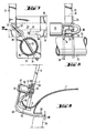
- the longitudinal strut 91 While the longitudinal strut 91 is rigid, the longitudinal strut 92, which connects the free ends of the rods 82, is rotatably supported therein so that a pawl 93 rigidly connected to the longitudinal strut 92, which is attached adjacent to the end of the longitudinal strut 92, with this is rotatable.
- a pawl 93 In Fig.16 such a pawl is shown only in the bracket 5. However, it goes without saying that a corresponding one can also be attached to the bracket 6.
- the pawl 93 engages, as can be seen in FIG. 17, in a lug 94, which can be formed, for example, by the outwardly projecting end of the pin 86.
- a spring 95 carries the pawl 93 in the locked position and thus prevents the rods from slipping out unintentionally.
- a sleeve piece 96 is welded, which is provided with an internal thread, via which a central rod 97 can be screwed in, which serves as a lever arm for rotating the longitudinal strut 92 about its longitudinal axis and thus for unlocking the pawl 93.
- the central rod 97 carries at its end a foot part 98 with which the central rod 97 can be set up on the floor when the position shown in FIG. 13 has been assumed by the roof rack.
- further fastening options for additional struts can be provided, which serve to stabilize the awning.
- the frame formed between the rods 82 and the longitudinal struts 91 and 92 can be covered by means of a firm but resilient hard PVC cover, such as 74 for the partial covering in the embodiment shown in FIG is indicated.
- a tarpaulin cover 99 which can be wound up on a roll 100 when not required.
- the side walls of the awning, which are indicated with 1 0 1, 102, are fastened to the rods 82 or the longitudinal strut 92 in a known manner.
Landscapes
- Engineering & Computer Science (AREA)
- Mechanical Engineering (AREA)
- Fittings On The Vehicle Exterior For Carrying Loads, And Devices For Holding Or Mounting Articles (AREA)
Applications Claiming Priority (4)
| Application Number | Priority Date | Filing Date | Title |
|---|---|---|---|
| DE3203753 | 1982-02-04 | ||
| DE3203753 | 1982-02-04 | ||
| DE19823220417 DE3220417A1 (de) | 1982-02-04 | 1982-05-29 | Dachgepaecktraeger |
| DE3220417 | 1982-05-29 |
Publications (2)
| Publication Number | Publication Date |
|---|---|
| EP0085964A2 true EP0085964A2 (fr) | 1983-08-17 |
| EP0085964A3 EP0085964A3 (fr) | 1984-10-10 |
Family
ID=25799342
Family Applications (1)
| Application Number | Title | Priority Date | Filing Date |
|---|---|---|---|
| EP83101071A Withdrawn EP0085964A3 (fr) | 1982-02-04 | 1983-02-04 | Galerie |
Country Status (2)
| Country | Link |
|---|---|
| EP (1) | EP0085964A3 (fr) |
| DE (1) | DE3220417A1 (fr) |
Cited By (4)
| Publication number | Priority date | Publication date | Assignee | Title |
|---|---|---|---|---|
| FR2596344A1 (fr) * | 1986-03-26 | 1987-10-02 | Boisgerault Michel | Dispositif de galerie mobile pour vehicule automobile |
| DE3626896A1 (de) * | 1986-08-08 | 1988-02-11 | Harald Schmieder | Gepaecktraeger fuer kraftfahrzeuge |
| GB2216474A (en) * | 1988-03-07 | 1989-10-11 | Autopia Terakat Accessories | Adjustable load rack for a vehicle |
| GB2267261A (en) * | 1992-05-26 | 1993-12-01 | David Tonks | Collapsible roof rack |
Families Citing this family (7)
| Publication number | Priority date | Publication date | Assignee | Title |
|---|---|---|---|---|
| US4728244A (en) * | 1985-07-05 | 1988-03-01 | Svend Stokkendal | Combined roof rack for a car and two-wheel cart |
| US5651484A (en) * | 1995-08-11 | 1997-07-29 | Fugman; Lowell S. | Ladder support accessory for truck rack |
| US5690259A (en) * | 1996-05-02 | 1997-11-25 | Montani; John J. | Modular bicycle rack system |
| DE10007078A1 (de) * | 2000-02-16 | 2001-08-23 | Karlheinz Barbulla | Vorrichtung zum Transport von länglichen Gegenständen, Aufnahmeeinheit sowie Verwendung für eine Aufnahmeeinheit |
| USD888648S1 (en) * | 2018-05-30 | 2020-06-30 | Yakima Products, Inc. | Tower for vehicle rack |
| USD888647S1 (en) * | 2018-05-30 | 2020-06-30 | Yakima Products, Inc. | Tower for vehicle rack |
| CN113859129B (zh) * | 2021-09-08 | 2024-01-09 | 德田丰新材料江苏有限公司 | 用于汽车行李架管内螺母柔性对孔设备 |
Family Cites Families (7)
| Publication number | Priority date | Publication date | Assignee | Title |
|---|---|---|---|---|
| US2506421A (en) * | 1946-12-13 | 1950-05-02 | Fred H Hacker | Car top carrier |
| US3169653A (en) * | 1962-11-19 | 1965-02-16 | Emil A Stromberg | Loader-carrier for automobiles |
| US3460694A (en) * | 1967-09-18 | 1969-08-12 | John R Simms | Car top boat handling device |
| US4081095A (en) * | 1977-03-25 | 1978-03-28 | Wilburn Everett R | Vehicle top article carrier |
| DE2836311C2 (de) * | 1978-08-18 | 1983-09-22 | Heinrich Wunder GmbH & Co KG, 8060 Dachau | Dachträger für Kraftfahrzeuge |
| NO143483C (no) * | 1979-01-22 | 1981-02-25 | Stokkendal & Co | Anordning ved takgrind for bil. |
| DE3025746A1 (de) * | 1980-07-08 | 1982-01-28 | Walter Ing.(grad.) 4000 Düsseldorf Westerfrölke | Verladevorrichtung fuer autodachboote |
-
1982
- 1982-05-29 DE DE19823220417 patent/DE3220417A1/de not_active Withdrawn
-
1983
- 1983-02-04 EP EP83101071A patent/EP0085964A3/fr not_active Withdrawn
Cited By (5)
| Publication number | Priority date | Publication date | Assignee | Title |
|---|---|---|---|---|
| FR2596344A1 (fr) * | 1986-03-26 | 1987-10-02 | Boisgerault Michel | Dispositif de galerie mobile pour vehicule automobile |
| DE3626896A1 (de) * | 1986-08-08 | 1988-02-11 | Harald Schmieder | Gepaecktraeger fuer kraftfahrzeuge |
| GB2216474A (en) * | 1988-03-07 | 1989-10-11 | Autopia Terakat Accessories | Adjustable load rack for a vehicle |
| GB2216474B (en) * | 1988-03-07 | 1992-06-17 | Autopia Terakat Accessories | A load carrier for a commercial vehicle |
| GB2267261A (en) * | 1992-05-26 | 1993-12-01 | David Tonks | Collapsible roof rack |
Also Published As
| Publication number | Publication date |
|---|---|
| DE3220417A1 (de) | 1983-08-11 |
| EP0085964A3 (fr) | 1984-10-10 |
Similar Documents
| Publication | Publication Date | Title |
|---|---|---|
| DE3888364T3 (de) | Eine lasttragende vorrichtung. | |
| EP0101054B1 (fr) | Porte-bagages pour véhicules notamment pour caravanes | |
| DE68901714T2 (de) | Radbremsblock. | |
| DE68906203T2 (de) | Koffer. | |
| DE10317960A1 (de) | Fahrzeuggepäckträger zur Lagerung von Gegenständen benachbart zur Hecktür eines Kraftfahrzeuges | |
| EP0019873B1 (fr) | Dispositif porte-bagages à fixer sur un toit de véhicule | |
| DE202022105698U1 (de) | Fahrzeugdachträgerbaugruppe | |
| DE102018117946A1 (de) | Tischvorrichtung für ein Kraftfahrzeug | |
| EP0085964A2 (fr) | Galerie | |
| DE102010011086B4 (de) | Anordnung mindestens eines Funktionsmoduls auf einem Fahrzeugboden eines Fahrzeugs | |
| EP2216204A1 (fr) | Galerie pour véhicules automobiles | |
| DE102018122634B4 (de) | Ladungs-Sicherungs-System sowie Fahrzeug umfassend ein solches System und ein Verfahren zur Ladungs-Sicherung | |
| EP0939005A1 (fr) | Dispositif pour fixer des articles dans le compartiment à bagages d'un véhicule | |
| DE10102662A1 (de) | Windschotteinrichtung | |
| DE3327755A1 (de) | Bewegliche verdeckvorrichtung fuer fahrzeuge, insbesondere lastkraftwagen | |
| DE68907773T2 (de) | Dachtraeger fuer fahrzeuge zum befestigen ohne externe stuetzen. | |
| EP2520451B1 (fr) | Superstructure bâchée pour un véhicule utilitaire | |
| DE102009025034A1 (de) | Fahrzeuggepäckträger mit einseitig lösbaren und verstaubaren Querträgern | |
| DE2908176C2 (fr) | ||
| DE3318891A1 (de) | Zweiteiliger kombi-dachtraeger | |
| EP2607176B1 (fr) | Support de charge avec une pièce porte-charge et un élément d'appui | |
| DE3315335A1 (de) | Dachtraeger fuer kraftfahrzeuge | |
| DE3626896A1 (de) | Gepaecktraeger fuer kraftfahrzeuge | |
| DE3425016A1 (de) | Schiebeverdeck-planengestell | |
| DE4213950C2 (de) | Querstütze an der Ladefläche eines Lastfahrzeugs |
Legal Events
| Date | Code | Title | Description |
|---|---|---|---|
| PUAI | Public reference made under article 153(3) epc to a published international application that has entered the european phase |
Free format text: ORIGINAL CODE: 0009012 |
|
| AK | Designated contracting states |
Designated state(s): AT BE CH DE FR GB LI NL SE |
|
| PUAL | Search report despatched |
Free format text: ORIGINAL CODE: 0009013 |
|
| AK | Designated contracting states |
Designated state(s): AT BE CH DE FR GB LI NL SE |
|
| STAA | Information on the status of an ep patent application or granted ep patent |
Free format text: STATUS: THE APPLICATION IS DEEMED TO BE WITHDRAWN |
|
| 18D | Application deemed to be withdrawn |
Effective date: 19850611 |
|
| RIN1 | Information on inventor provided before grant (corrected) |
Inventor name: SCHNITZLER, ROSEMARIE |