EP0939005A1 - Dispositif pour fixer des articles dans le compartiment à bagages d'un véhicule - Google Patents
Dispositif pour fixer des articles dans le compartiment à bagages d'un véhicule Download PDFInfo
- Publication number
- EP0939005A1 EP0939005A1 EP99101300A EP99101300A EP0939005A1 EP 0939005 A1 EP0939005 A1 EP 0939005A1 EP 99101300 A EP99101300 A EP 99101300A EP 99101300 A EP99101300 A EP 99101300A EP 0939005 A1 EP0939005 A1 EP 0939005A1
- Authority
- EP
- European Patent Office
- Prior art keywords
- carrier
- locking
- vehicle
- attachment element
- telescopic
- Prior art date
- Legal status (The legal status is an assumption and is not a legal conclusion. Google has not performed a legal analysis and makes no representation as to the accuracy of the status listed.)
- Withdrawn
Links
- 125000006850 spacer group Chemical group 0.000 claims description 12
- 239000000969 carrier Substances 0.000 claims description 7
- 230000001154 acute effect Effects 0.000 claims description 5
- 229910052782 aluminium Inorganic materials 0.000 claims description 3
- XAGFODPZIPBFFR-UHFFFAOYSA-N aluminium Chemical compound [Al] XAGFODPZIPBFFR-UHFFFAOYSA-N 0.000 claims description 3
- 229910052751 metal Inorganic materials 0.000 claims description 3
- 239000002184 metal Substances 0.000 claims description 3
- 239000003795 chemical substances by application Substances 0.000 description 2
- 230000000694 effects Effects 0.000 description 2
- 238000007373 indentation Methods 0.000 description 2
- 238000009434 installation Methods 0.000 description 2
- 239000004575 stone Substances 0.000 description 2
- 230000006835 compression Effects 0.000 description 1
- 238000007906 compression Methods 0.000 description 1
- 238000006073 displacement reaction Methods 0.000 description 1
- 239000000834 fixative Substances 0.000 description 1
- 238000003780 insertion Methods 0.000 description 1
- 230000037431 insertion Effects 0.000 description 1
- 239000000463 material Substances 0.000 description 1
Images


Classifications
-
- B—PERFORMING OPERATIONS; TRANSPORTING
- B60—VEHICLES IN GENERAL
- B60R—VEHICLES, VEHICLE FITTINGS, OR VEHICLE PARTS, NOT OTHERWISE PROVIDED FOR
- B60R5/00—Compartments within vehicle body primarily intended or sufficiently spacious for trunks, suit-cases, or the like
- B60R5/04—Compartments within vehicle body primarily intended or sufficiently spacious for trunks, suit-cases, or the like arranged at rear of vehicle
-
- B—PERFORMING OPERATIONS; TRANSPORTING
- B60—VEHICLES IN GENERAL
- B60R—VEHICLES, VEHICLE FITTINGS, OR VEHICLE PARTS, NOT OTHERWISE PROVIDED FOR
- B60R7/00—Stowing or holding appliances inside vehicle primarily intended for personal property smaller than suit-cases, e.g. travelling articles, or maps
- B60R7/02—Stowing or holding appliances inside vehicle primarily intended for personal property smaller than suit-cases, e.g. travelling articles, or maps in separate luggage compartment
Definitions
- the invention relates to a device according to the preamble of patent claim 1.
- Such a device known from DE 296 08 955 U1 has two guide elements on, in which telescopically movable guide rails are provided.
- the guide elements are by connecting elements for a parallel arrangement connected with each other.
- This guide unit is fastened with the connecting elements using screws or other fasteners on the floor of the cargo area.
- the connecting elements with which the telescopic guide elements or carrier rails are attached to the floor of the cargo space extend transversely to Vehicle longitudinal direction.
- the known device is for permanent attachment in Motor vehicle determines what a permanent redesign of the luggage space results.
- the object of the invention is to provide a device of the type mentioned in the introduction, the one with simple handling without changes to the body in the luggage compartment Motor vehicle can be used.
- the extendable carrier device has two extending in the vehicle longitudinal direction telescopic support rails that run along the two side boundaries of the Luggage compartment of the motor vehicle can be arranged.
- Each of the two telescopic Carrier rails are in an elongated, extending in the vehicle longitudinal direction Telescopic carrier led.
- Each of the two telescopic carriers is on the vehicle body or releasably locked to body-fixed vehicle parts.
- the load carriers are designed so that objects can be attached to them.
- the telescopic carrier rail can consist of an external carrier rail and an inner carrier rail exist, the inner carrier rail is firmly connected to the telescopic carrier and the outer carrier rail Has fixing means for the load carrier.
- additional rails can be provided to extend the telescopic extension.
- the fixing means can be designed in such a way that they can be used for fastening Cross members in various positions in the vehicle longitudinal direction on the outer support rail can be detachably attached. Two or more crossbeams can also be used here are attached to the support rails at certain intervals from one another. Furthermore, the respective outer carrier rail can have a longitudinal groove that extends in the longitudinal direction of the vehicle extends. This longitudinal groove can be used to move the Cross members in the longitudinal direction along the support rails when finding the corresponding Serve position. Furthermore, the longitudinal groove can serve to support the platform, the two longitudinal edges of the platform into the guide grooves of the two support rails is inserted. Fixing means can also be provided for the platform to attach the platform to the outer support rail.
- the locking and locking devices with which the telescopic carrier on the body or the body-fixed parts are releasably connected and with which the Detachable attachment of the respective load carrier to the carrier rails in the area of Fixing agent takes place, can be operated by hand. This makes it possible without Special tools the fastening device in the motor vehicle, which one on the Motor vehicle on the market, for example station wagon, caravan, minivan and the like. Can be releasably attached as required.
- cross member cross member, loading platform
- Additional tool releasable locks can be provided in order to be transported Connect objects firmly to the load carrier.
- At least one attachment element which can be displaced along the cross member can be on the cross member be provided in different positions along the cross member, can be locked in particular by a clamp fit.
- the holding device can be pivoted within an acute swivel angle range and can at least in the two end positions of the acute swivel angle range fixed to the attachment element by means of locking means which can also be operated by hand become.
- Such an attachment element can also be used in a preferred manner a cross member, for example on the outside of the vehicle, in particular on Roof, provided support device is used.
- the movable actuating device preferably acting with leverage, can Jaws moved from its released position to the clamping position become.
- the actuating element designed like a flap can have a cross section have curved actuating surface, which with the movable jaws is brought into investment. To bring the jaws into their clamping position, the operating surface is rotated so that its radius of curvature increases, whereby the clamping jaw is moved into the clamping position.
- the one on the actuator provided flap-shaped lever arm, which can be pivoted by hand can, is much larger than the lever arm with which the actuating surface acts on the jaws. In the clamped position, the actuator is activated Self-holding effect held when the lever part of the actuating element is folded down.
- the attachment element can be, which hold the holding device immovably in the respective end position.
- at least one of the stops which is also used as a locking element for locking can serve the holding device in an intermediate position, movable on Attachment element can be stored.
- the locking element is preferably pin-shaped and extends perpendicular to the longitudinal extent of the cross member, in particular in a horizontal plane.
- the locking element is in its axial direction slidably mounted on the attachment element. Can be used to actuate the locking element this with the actuating element with which the movable jaws are actuated will be connected.
- the holding device is normally held in an approximately horizontal end position and can be adjusted in an upper or lower end position Attachment element can be stored.
- Attachment element can be stored.
- the fact that the holding device in a lower or upper end position is pivotable, the transport height of the respective object, for example, a bicycle. Also the one to be transported Object to be brought into a convenient transport position.
- the holding device is designed in such a way that different holding elements, with which various objects can be attached to the holding device are provided.
- retaining elements can optionally be used with fixing screws, with the fork ends of a front fork of a bicycle, a front wheel holder or holding rods and other holding elements can be attached be.
- a loading platform can be used as a load carrier, which can Side edges running in the longitudinal direction of the vehicle can be inserted into the mounting rails, be provided.
- a manually operated locking device is also on the loading platform provided to secure the loading platform to the support rails for transport connect to.
- the side edges of the loading platform can fit into the longitudinal grooves the carrier rails can be used for transport.
- the Locking by spring force automatically in appropriate fixation means on the support rails snaps into place.
- On the loading platform can be used to fix the to be transported Objects fixative may be provided. These can be in the form of recesses be designed to be automatically lockable in the feet of containers with spring force are. With the help of a manually operated central actuation device can lock the container feet against the locking spring force again be solved.
- the loading platform can consist of an upper and a lower plate, which are parallel to each other lie and spacers arranged therebetween. Through the Spacers, which are preferably designed as rectangular hollow profiles in rod form, sufficient strength of the platform is achieved.
- the two plates and the spacers can be made of relatively thin material, so that the platform has only a low weight, but sufficient strength for the safe Transport of objects, especially containers, guaranteed.
- the platform can be in preferably be made of light metal, in particular aluminum, wherein it is formed in one piece from an extruded profile.
- a multifunctional charging and Transport system for arrangement in a luggage compartment of a motor vehicle created.
- the installation and removal of this transport system from the Vehicle is simple because the locking and locking devices provided for this purpose are easily removable by hand. Tools are not required here.
- the load carriers in particular in the form of cross beams or in the form of a loading platform, are extendable mounted on the telescopic support rail system, making it easy Loading in the extended position is made possible.
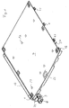
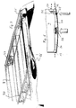
- FIG. 1 and 2 are exemplary embodiments of a perspective view multifunctional fastening device for objects in the trunk or Luggage compartment of a motor vehicle are shown.
- the device is designed as a multi-function carrier device.
- a board-shaped flat loading platform 7 is used as the load carrier.
- the load carrier consists of cross beams 8.
- the respective load carrier (Loading platform 7, cross member 8) is on the side extending in the vehicle longitudinal direction Telescopic carriers 13 stored.
- Each of the two telescopic supports 13 has telescopic support rails, which consist of rail parts inserted into each other, the multifunction carrier installed in the luggage compartment of the vehicle can be pulled out of the vehicle in reverse.
- the loading platform 7 and the Cross members 8 are mounted on the respective outer carrier rail 1.
- the guide grooves 4 of the two support rails 1 are on the inside of the telescopic carrier 13 and face each other in the installed state.
- the loading platform 7 is inserted and stored in the guide grooves 4, such as it is shown in FIG. 1. By means of sliding elements (sliding blocks) 47, the loading platform can 7 can be moved in the grooves 4.
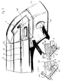
- Fixing means 5, 6, which can be designed as depressions, for example, intended.
- these fixing means 5, 6 are located in the area of the guide groove 4 (FIG. 3).
- FIG. 6 there are at the rear end of the loading platform 7 engaging means 57, which by spring force in the corresponding fixing means 6 (depressions of the carrier rails 1) are pressed in.
- the loading platform 7 becomes fixed to the carrier rails 1 during transport connected.
- each end piece has an engagement means 11, for example in the form of one in the End piece 36 sliding locking element (locking stone).
- the locking element is acted upon by a locking spring 37 and in the locking position (Fig. 4 (A)) pressed.
- the engaging means 11 comes into engagement with a respective fixing means 5 (recess) on the carrier rail 1. This is the respective cross member 8 in the longitudinal direction in certain positions on the support rails 1 fixed.
- Push button 35 disengaged the engagement means 11 from the fixing means 5.
- a release bevel 38 which cooperates with the engagement means 11 in such a way that when the Push button 35 (Fig. 4 (B)) engages the means 11 against the force of the locking spring 37 is brought out of engagement with the fixing means 5 designed as a recess.
- the Cross members 8 can then in the longitudinal direction of the support rails on the support rails 1 are moved along the grooves 4 and detached from the carrier rails 1 or in other positions with the support rails 1, wherein again the corresponding engagement means 11 in the end pieces 36 with the fixing means 5 (depressions) on the support rails.
- Fig. 3 is located the locking of the support rails at the rear end of the telescopic support 13 and has a push button 38.
- the lock can be designed in the same way be like the locking device shown in FIG. 4.
- a locking stone (Locking element) 70 by means of spring force (compression spring 71) in a locking position are pressed in which the carrier rail 1 against pulling out on the telescopic carrier 13 is secured (detailed illustration (A).
- the lock By means of the manually operable Push button 38, the lock can be released so that the support rails 1 together can be pulled out with the platform 7 or the cross members 8 (Detail view (B)).
- the pushbutton 38 can be used to unlock the slope 72, which cooperates with the locking block 70, moved in the manner be that this against the force of the locking spring 71 from the locking position brought.
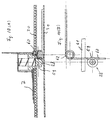
- the unlocking is by means of a manually operated Push button 40 against the restoring force of a restoring spring 67 and the locking force a locking spring 69 causes.
- a locking spring 69 In the locked state, which in the Figures 9 (B) and (C) are shown, engage by the locking spring 9 Locking leg 65 in correspondingly shaped lateral locking grooves a locking bolt 66, which in the locked state in the recess 64 of the Vehicle floor is inserted.
- the locking bolt 66 is about a pivot axis 69 swiveling.
- the locking button 40 is on the locking bolt 66 rotatably connected crank 68 articulated.
- the locking bolt 66 By the force of the return spring 67, which acts on the push button 40, the locking bolt 66 in the in the figures shown position held, in which the two locking legs 65 by the Locking spring 69 are pressed into the corresponding locking grooves.
- the locking bolt 66 pivoted about the pivot axis 69, so that the locking leg 65 are pressed out of the locking grooves and on a smooth the cylindrical surface of the locking bolt.
- the locking bolt can then be pulled out of the recess 64.
- the locking leg 65 by the force of the locking spring 69 snap into the locking grooves so that the rear end of each Telescopic carrier 13 is secured against pulling out.
- At least one attachment element 14 may be provided (FIGS. 5 (A) to (G)).
- the attachment element 14 can in its unlocked or unlocked position along the cross member 8 be moved. By locking or locking it can be in a respective suitable position on the cross member 8 are fixed.
- Located on the attachment element 14 a holding device 16.
- the holding device 16 is around one for longitudinal expansion of the cross member 8 vertically in particular horizontally extending axis 15 mounted on the attachment element 14.
- the pivot axis 15 can from one on the clamping jaw 17 supported journals 76 are formed.
- the holding device can be within an acute swivel angle that is up to about 60 °, in particular about 40 ° can be pivoted.
- the pivoting of the holding device 16 can between a first lower position (Fig. 5 (B)), in which the holding device 16 is essentially a horizontal position, and an upper end position in which the holding device 16 can be pivoted upwards by the acute swivel angle.
- the holding device 16 forms part of the attachment element 14.
- a second part of the Attachment element 14 is a slidable part on the cross member 8, which is essentially is formed by jaws 17 and 18.
- the jaws 17, 18 are used for fixation of the attachment element 14, the clamping jaws being brought into a clamping position become. For moving the attachment element 14 along the cross member 8 this clamping position is released.
- the clamping jaws 18 are in particular horizontal Direction perpendicular to the extension of the cross member 8 movable on the attachment element 14 stored.
- Parallel guide webs 73 formed on the clamping jaws 18 (Fig. 5 (B)) are used to guide the jaws 17.
- To move the jaws 18 serves a manually actuable actuating element 20 in the form of a lever effect having flap.
- the actuating element 20 is pivotable about an axis 22 stored.
- a locking element 19 (Fig. 5 (B)) vertically movable to the longitudinal extent of the cross member 8.
- the locking element 19 also extends through the clamping jaws 18.
- the locking element 19 is preferably designed as a locking pin in the direction of its longitudinal axis 21 is movably mounted on the attachment element or the clamping jaws 17, 18.
- the pen-shaped Locking element 19 can be provided with a locking end 45 via a rear side a circuit board 74 defined locking level 46 (Fig. 5 (G)) beyond and behind this locking level 46 are moved out. In one from the front of the of the holding device 16 attached to the printed circuit board 74 are delimiting surfaces the holding device 16 and the jaw 17 sliding against each other.
- the locking end 45 (Fig. 5 (D)
- the holding device 16 in different Angular positions when pivoting about the pivot axis 15 (Fig. 5 (A), (B)) being held.
- arcuate recess or backdrop 75 may be provided through which the arrester 45 protrudes.
- the upper closed end of the arcuate recess 75 is in the horizontal positioning of the holding device 16 on the through the recess projecting pin-shaped locking element 19. That compared to the slit-shaped Recess 75 widened locking end 45 lies when clamping the clamping jaws 17, 18 on the cross member 8 on the rear side (locking plane 46) of the board 74 so that the clamping force is supported on the back of the board 74. At the same time this allows the holding device 16 in different angular positions when pivoting lock around the pivot axis 15.
- one or both ends of the arcuate recess 75 can also a pivoting of the holding device 16 down against one example provided in the area of the bearing pin 76 provided stop.
- a region that extends beyond the circular arc-shaped region of the recess 75 can also be used Swiveling of the holding device 16 take place when the lower end of this Recess is open.
- the axis 22 can which the actuating element 20 is pivotally mounted.
- the axis 22 can be formed on or attached to the locking element 19 Pen be formed. Due to the pin-shaped design of the locking element 19, this can rotatable about its longitudinal axis 21 on the attachment element or the fixed clamping jaws 17 be stored. This also makes the actuating element pivotable 20 around the longitudinal axis 21 of the locking element 19. Hereby the actuating surface 41 can be detached from the contact surface 43 and detached from it Be held apart.
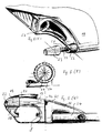
- Holding elements are provided on the holding device 16 in order to hold different objects to be able to attach to the holding device.
- These holding elements can For example, consist of fixing screws 23 (Fig. 5 (E)), which on a fixing pin 50 are stored. It is sufficient if one of the two fixing screws 23 on a thread the fixing pin 50 is screwed on, while the other fixing screw with the Fixing pin is connected. Between the fixing screws 23 and stops 52 on the Holding device 16 can in particular springs wound around the fixing pin 50 Coil springs 51 may be provided. On the fixing pin 50 and between the stops 52 and the fixing screws 23 can fork ends of a front fork one Bicycle used and by tightening one of the two fixing screws 23 on the Holding device 16 are fixed. It is also possible to use support rods 25a for a saddle holder or support rods 25b for holding a handlebar of a bicycle (Fig. 2) on Fixing pin 50 or otherwise to store.
- one or more insertion openings 53 can be provided on the holding device 16 into which one or more support rods 24 for front wheel holders (FIG. 5 (F) and (G)) can be used.
- a front wheel 54 of a bicycle can be attached (Fig. 5 (F))).
- the holding device 16 can be in an upper or lower position the pivot axis 15 are pivoted so that the installation height of the holding device attached bike can be reduced.
- the holding rods can be pivoted, with Using the fixing screws 23, the handrails in any desired pivot position can be fixed.
- the handrails can be designed in such a way that they certain components of a bicycle or other object in the luggage compartment of the vehicle to be transported, can be firmly connected. This ensures safe storage of the object in the luggage compartment of the vehicle guaranteed while driving.
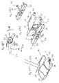
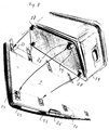
- the loading platform 7 shown in FIGS. 6, 7 and 8 can, as shown in FIG. are stored along their side edges in the mounting rails 1.
- the Side edges are preferably inserted into the longitudinal grooves 4 of the carrier rails 1.
- Means the sliding elements 47 (Fig. 1) is a simple displacement of the platform 7 in the Guide grooves 4 reached.
- the engagement means 57 Fig. 6
- a fixation of the Loading platform 7 achieved on the support rails 1 the engagement means 57 in the corresponding recesses (openings) 6 of the carrier rails 1 (Fig. 2 and 3) intervention.
- This locking of the loading platform 7 takes place by spring force, which on the engagement means 12 acts and they in the corresponding recesses 6 of the support rails presses.
- the engagement means 57 against the force of the locking spring from its engaged position Pulling out of the recesses 6 can be solved so that the loading platform along the guide groove 4 shifted in the carrier rails 1 or out of the carrier rail 1 can be removed.
- the push button movement is via a hinge mechanism 56 on the engagement means 57 on one or both side edges of the loading platform 7 transferred.
- a actuator 26 preferably provided on the rear of the loading platform 7 operated by hand.
- the movement of the flap, which is preferably designed as a manually operable flap Actuator 26 is over rods 34 with laterally protruding Transfer the rod ends 12 to the pushbuttons 38 of the carrier rail lock.
- the push button 38 Fig. 3 for unlocking the carrier rail lock especially operated by indentation.
- the carrier rails 1 released from their locked position with the telescopic supports 13 so that the support rails 1 can be pulled out telescopically from the luggage compartment. It is possible with the help of an actuating device 26 at the end of the loading platform To release carrier rail locks together.
- the carrier rail locks can be designed in the manner related above was described with FIG. 3.
- the loading platform 7 is supported by an upper plate 30 and a lower plate 31, the two plates being separated by spacers 32 kept apart from each other.
- the spacers 32 can be rectangular hollow profiles form.
- the plates 30 and 31 and the spacers 32 can be made in one piece from an extruded profile by cutting to length from an extruded profile be educated.
- the platform 7 preferably consists of light metal in particular Aluminum.
- the loading platform 7 can have fixation adapters, for example in the form of depressions 27 in the surface of the loading platform exhibit.
- Feet 28 (FIG. 8) which fit on the Bottom of containers 29 are arranged.
- the locking elements 60 are under spring tension, so that when inserting the feet 28 in the Indentations 27, the locking elements 60 are automatically pressed into the locking grooves 59.
- four feet 28, which may be sprung are stored (Fig. 10 (A)), may be provided.
Landscapes
- Engineering & Computer Science (AREA)
- Mechanical Engineering (AREA)
- Fittings On The Vehicle Exterior For Carrying Loads, And Devices For Holding Or Mounting Articles (AREA)
Applications Claiming Priority (2)
| Application Number | Priority Date | Filing Date | Title |
|---|---|---|---|
| DE1998103210 DE19803210C2 (de) | 1998-01-28 | 1998-01-28 | Vorrichtung zum Befestigen von Gegenständen im Gepäckraum eines Kraftfahrzeugs |
| DE19803210 | 1998-01-28 |
Publications (1)
| Publication Number | Publication Date |
|---|---|
| EP0939005A1 true EP0939005A1 (fr) | 1999-09-01 |
Family
ID=7855898
Family Applications (1)
| Application Number | Title | Priority Date | Filing Date |
|---|---|---|---|
| EP99101300A Withdrawn EP0939005A1 (fr) | 1998-01-28 | 1999-01-25 | Dispositif pour fixer des articles dans le compartiment à bagages d'un véhicule |
Country Status (2)
| Country | Link |
|---|---|
| EP (1) | EP0939005A1 (fr) |
| DE (1) | DE19803210C2 (fr) |
Cited By (1)
| Publication number | Priority date | Publication date | Assignee | Title |
|---|---|---|---|---|
| EP2338738A2 (fr) | 2009-12-17 | 2011-06-29 | Skoda Auto a.s. | Moyen de fixation excentrique universel |
Families Citing this family (11)
| Publication number | Priority date | Publication date | Assignee | Title |
|---|---|---|---|---|
| DE10117122A1 (de) * | 2001-04-06 | 2001-10-04 | Audi Ag | Kraftfahrzeug mit einem Dachreling-Trägersystem |
| DE10228360A1 (de) * | 2002-06-25 | 2004-01-15 | Volkswagen Ag | Zur Positionierung von Gegenständen in einem Fahrzeuginnenraum ausgelegter Rahmen |
| DE10333630B4 (de) * | 2002-12-11 | 2004-10-21 | Uebler Gmbh | Befestigungseinrichtung für ein Transportgut sowie deren Verwendung insbesondere für ein Fahrrad |
| DE10321890B4 (de) | 2003-05-07 | 2005-10-27 | Bos Gmbh & Co. Kg | Befestigungsvorrichtung für einen Fahrzeugraum |
| DE202004005126U1 (de) * | 2004-04-01 | 2005-08-18 | Hachenburg, Bruno | Fahrradhalter und Pkw mit Fahrradhalter |
| DE102004041583A1 (de) * | 2004-08-26 | 2006-03-02 | Volkswagen Ag | Einrichtung zur Befestigung eines Gegenstandes in Sitzschienen eines Fahrzeugbodens |
| DE102005030386B4 (de) * | 2005-06-29 | 2013-05-29 | Webasto Ag | Fahrzeug mit einer bewegbaren Beladeeinrichtung |
| DE102007048894A1 (de) * | 2007-10-11 | 2009-04-16 | Sortimo Speedwave Gmbh | Lösbares Befestigungssystem für Ladegut |
| FR2941419B1 (fr) * | 2009-01-27 | 2011-04-22 | Peugeot Citroen Automobiles Sa | Dispositif de support d'un moyen de transport a deux roues dans une partie arriere de l'habitacle d'un vehicule |
| DE102009019866B4 (de) * | 2009-05-06 | 2023-05-25 | Rheinmetall Landsysteme Gmbh | Modularer Ausrüstungsträger |
| DE102011112115A1 (de) * | 2011-09-02 | 2013-03-07 | GM Global Technology Operations LLC (n. d. Gesetzen des Staates Delaware) | Schiene zur Lagerung eines Funktionsteils in einem Innenraum eines Kraftfahrzeugs |
Citations (6)
| Publication number | Priority date | Publication date | Assignee | Title |
|---|---|---|---|---|
| US5046913A (en) * | 1990-02-08 | 1991-09-10 | Domek Robert F | Quick install and remove slidable carrying table for vehicles |
| US5161700A (en) * | 1991-01-28 | 1992-11-10 | Prince Corporation | Adjustable storage system for a vehicle |
| DE4132954A1 (de) * | 1991-10-04 | 1993-04-08 | Helmut Walter Sterzel | Vorrichtung zum unterteilen eines kraftfahrzeug-kofferraums |
| EP0681942A1 (fr) * | 1994-05-11 | 1995-11-15 | Framtid Kredit Und Finanz Anstalt | Dispositif d'appui pour une plateforme de chargement d'un véhicule |
| DE29608955U1 (de) * | 1996-05-10 | 1996-09-26 | Jähne, Johannes, 85053 Ingolstadt | Beladevorrichtung |
| EP0899158A2 (fr) * | 1997-08-27 | 1999-03-03 | Prince Corporation | Coffre expansible |
-
1998
- 1998-01-28 DE DE1998103210 patent/DE19803210C2/de not_active Expired - Fee Related
-
1999
- 1999-01-25 EP EP99101300A patent/EP0939005A1/fr not_active Withdrawn
Patent Citations (6)
| Publication number | Priority date | Publication date | Assignee | Title |
|---|---|---|---|---|
| US5046913A (en) * | 1990-02-08 | 1991-09-10 | Domek Robert F | Quick install and remove slidable carrying table for vehicles |
| US5161700A (en) * | 1991-01-28 | 1992-11-10 | Prince Corporation | Adjustable storage system for a vehicle |
| DE4132954A1 (de) * | 1991-10-04 | 1993-04-08 | Helmut Walter Sterzel | Vorrichtung zum unterteilen eines kraftfahrzeug-kofferraums |
| EP0681942A1 (fr) * | 1994-05-11 | 1995-11-15 | Framtid Kredit Und Finanz Anstalt | Dispositif d'appui pour une plateforme de chargement d'un véhicule |
| DE29608955U1 (de) * | 1996-05-10 | 1996-09-26 | Jähne, Johannes, 85053 Ingolstadt | Beladevorrichtung |
| EP0899158A2 (fr) * | 1997-08-27 | 1999-03-03 | Prince Corporation | Coffre expansible |
Cited By (2)
| Publication number | Priority date | Publication date | Assignee | Title |
|---|---|---|---|---|
| EP2338738A2 (fr) | 2009-12-17 | 2011-06-29 | Skoda Auto a.s. | Moyen de fixation excentrique universel |
| EP2338738A3 (fr) * | 2009-12-17 | 2011-12-28 | Skoda Auto a.s. | Moyen de fixation excentrique universel |
Also Published As
| Publication number | Publication date |
|---|---|
| DE19803210C2 (de) | 2000-10-19 |
| DE19803210A1 (de) | 1999-08-05 |
Similar Documents
| Publication | Publication Date | Title |
|---|---|---|
| DE2707893C2 (de) | Spannvorrichtung an einer Werkbank o.dgl. | |
| EP0298382B1 (fr) | Conteneur pour le stockage et le transport, en particulier de matériaux en vrac, comme des gravats, ordures, déchets industriels et analogues | |
| DE60310495T2 (de) | Tragbare Werkbank | |
| EP0754595B1 (fr) | Système variable de fixation rapide d?un coffre de toit sur les transverses d'une galerie de toit | |
| EP1522455B1 (fr) | Dispositif de protection de chargement dans les unités de transport | |
| EP0939005A1 (fr) | Dispositif pour fixer des articles dans le compartiment à bagages d'un véhicule | |
| EP0019873A1 (fr) | Dispositif porte-bagages à fixer sur un toit de véhicule | |
| DE69503672T2 (de) | Trägervorrichtung zum Transportieren, z.B. von Fahrrädern | |
| EP0737601B1 (fr) | Dispositif pour éviter le glissement des objets transportés sur des plate-formes de charge de véhicules | |
| EP2428406B1 (fr) | Support de charge coulissant et basculant | |
| DE4338759A1 (de) | Tragvorrichtung zur Anordnung an einem Fahrzeug | |
| DE10241269B4 (de) | Transportplattform mit variabler Geometrie für motorisierte Zweiräder, welche über ein lineares Führungssystem im eigentlichen Transportmittel bewegt und arretiert wird | |
| DE19838254C2 (de) | Transportchassis | |
| DE102009060366B4 (de) | Lastenträger | |
| DE2908176C2 (fr) | ||
| DE202018104929U1 (de) | Sicherungskeil | |
| DE2944102C2 (de) | Langholzträger | |
| DE102015108555A1 (de) | Fahrradträger | |
| EP2765032B1 (fr) | Support de charge avec pièces porte-charge stockées en mouvement sur un support de base | |
| EP2607176B1 (fr) | Support de charge avec une pièce porte-charge et un élément d'appui | |
| DE102008064332A1 (de) | Transportvorrichtung | |
| DE4137576C2 (de) | Vorrichtung zur lösbaren Halterung von Gegenständen an einem Fahrzeugsitz | |
| DE102021207883B3 (de) | Trägersystem für ein Zweirad | |
| EP0887250A2 (fr) | Support pour récipients en général et en particulier pour serviettes, utilisable pour motorcyclettes ou similaires | |
| DE102004008506B4 (de) | Vorrichtung zum Transport von Teilen im Kraftfahrzeug-Karosseriebau |
Legal Events
| Date | Code | Title | Description |
|---|---|---|---|
| PUAI | Public reference made under article 153(3) epc to a published international application that has entered the european phase |
Free format text: ORIGINAL CODE: 0009012 |
|
| AK | Designated contracting states |
Kind code of ref document: A1 Designated state(s): AT DE ES FR GB IT SE |
|
| AX | Request for extension of the european patent |
Free format text: AL;LT;LV;MK;RO;SI |
|
| 17P | Request for examination filed |
Effective date: 19991015 |
|
| RAP1 | Party data changed (applicant data changed or rights of an application transferred) |
Owner name: HS-PRODUCTS KAROSSERIESYSTEME GMBH |
|
| AKX | Designation fees paid |
Free format text: AT DE ES FR GB IT SE |
|
| 17Q | First examination report despatched |
Effective date: 20020228 |
|
| GRAH | Despatch of communication of intention to grant a patent |
Free format text: ORIGINAL CODE: EPIDOS IGRA |
|
| STAA | Information on the status of an ep patent application or granted ep patent |
Free format text: STATUS: THE APPLICATION IS DEEMED TO BE WITHDRAWN |
|
| 18D | Application deemed to be withdrawn |
Effective date: 20030806 |