EP0086042B1 - Production continue du dioxyde de chrome - Google Patents
Production continue du dioxyde de chrome Download PDFInfo
- Publication number
- EP0086042B1 EP0086042B1 EP83300220A EP83300220A EP0086042B1 EP 0086042 B1 EP0086042 B1 EP 0086042B1 EP 83300220 A EP83300220 A EP 83300220A EP 83300220 A EP83300220 A EP 83300220A EP 0086042 B1 EP0086042 B1 EP 0086042B1
- Authority
- EP
- European Patent Office
- Prior art keywords
- reaction
- pressure
- extruder
- reactor
- reaction zone
- Prior art date
- Legal status (The legal status is an assumption and is not a legal conclusion. Google has not performed a legal analysis and makes no representation as to the accuracy of the status listed.)
- Expired
Links
- AYTAKQFHWFYBMA-UHFFFAOYSA-N chromium(IV) oxide Inorganic materials O=[Cr]=O AYTAKQFHWFYBMA-UHFFFAOYSA-N 0.000 title claims description 21
- 229940090961 chromium dioxide Drugs 0.000 title claims description 8
- IAQWMWUKBQPOIY-UHFFFAOYSA-N chromium(4+);oxygen(2-) Chemical compound [O-2].[O-2].[Cr+4] IAQWMWUKBQPOIY-UHFFFAOYSA-N 0.000 title claims description 8
- 230000015572 biosynthetic process Effects 0.000 title claims description 7
- 238000003786 synthesis reaction Methods 0.000 title claims description 7
- 238000006243 chemical reaction Methods 0.000 claims description 58
- XLYOFNOQVPJJNP-UHFFFAOYSA-N water Substances O XLYOFNOQVPJJNP-UHFFFAOYSA-N 0.000 claims description 31
- 238000000034 method Methods 0.000 claims description 17
- 238000002156 mixing Methods 0.000 claims description 17
- 230000008569 process Effects 0.000 claims description 17
- 239000002002 slurry Substances 0.000 claims description 16
- 239000000203 mixture Substances 0.000 claims description 15
- QVGXLLKOCUKJST-UHFFFAOYSA-N atomic oxygen Chemical compound [O] QVGXLLKOCUKJST-UHFFFAOYSA-N 0.000 claims description 11
- WGLPBDUCMAPZCE-UHFFFAOYSA-N chromium trioxide Inorganic materials O=[Cr](=O)=O WGLPBDUCMAPZCE-UHFFFAOYSA-N 0.000 claims description 11
- 239000001301 oxygen Substances 0.000 claims description 11
- 229910052760 oxygen Inorganic materials 0.000 claims description 11
- 239000000047 product Substances 0.000 claims description 11
- 239000006227 byproduct Substances 0.000 claims description 9
- 238000002347 injection Methods 0.000 claims description 8
- 239000007924 injection Substances 0.000 claims description 8
- 238000013022 venting Methods 0.000 claims description 6
- 239000007795 chemical reaction product Substances 0.000 claims description 5
- 238000001816 cooling Methods 0.000 claims description 5
- 230000003247 decreasing effect Effects 0.000 claims description 4
- 238000007599 discharging Methods 0.000 claims description 4
- 239000013078 crystal Substances 0.000 claims description 3
- 238000005054 agglomeration Methods 0.000 claims 1
- 230000002776 aggregation Effects 0.000 claims 1
- 239000004615 ingredient Substances 0.000 description 15
- 239000000463 material Substances 0.000 description 15
- 230000005294 ferromagnetic effect Effects 0.000 description 7
- 238000010438 heat treatment Methods 0.000 description 7
- 230000005291 magnetic effect Effects 0.000 description 5
- 238000010923 batch production Methods 0.000 description 3
- 238000004519 manufacturing process Methods 0.000 description 3
- XEEYBQQBJWHFJM-UHFFFAOYSA-N Iron Chemical compound [Fe] XEEYBQQBJWHFJM-UHFFFAOYSA-N 0.000 description 2
- PXHVJJICTQNCMI-UHFFFAOYSA-N Nickel Chemical compound [Ni] PXHVJJICTQNCMI-UHFFFAOYSA-N 0.000 description 2
- 230000009471 action Effects 0.000 description 2
- 239000000654 additive Substances 0.000 description 2
- 229910045601 alloy Inorganic materials 0.000 description 2
- 239000000956 alloy Substances 0.000 description 2
- 230000008901 benefit Effects 0.000 description 2
- 239000000919 ceramic Substances 0.000 description 2
- 229910000423 chromium oxide Inorganic materials 0.000 description 2
- 238000010924 continuous production Methods 0.000 description 2
- 238000006073 displacement reaction Methods 0.000 description 2
- 230000010006 flight Effects 0.000 description 2
- 239000007789 gas Substances 0.000 description 2
- 230000005415 magnetization Effects 0.000 description 2
- 230000001590 oxidative effect Effects 0.000 description 2
- BASFCYQUMIYNBI-UHFFFAOYSA-N platinum Chemical compound [Pt] BASFCYQUMIYNBI-UHFFFAOYSA-N 0.000 description 2
- 239000007787 solid Substances 0.000 description 2
- 229910052721 tungsten Inorganic materials 0.000 description 2
- RYGMFSIKBFXOCR-UHFFFAOYSA-N Copper Chemical compound [Cu] RYGMFSIKBFXOCR-UHFFFAOYSA-N 0.000 description 1
- ZOKXTWBITQBERF-UHFFFAOYSA-N Molybdenum Chemical compound [Mo] ZOKXTWBITQBERF-UHFFFAOYSA-N 0.000 description 1
- RTAQQCXQSZGOHL-UHFFFAOYSA-N Titanium Chemical compound [Ti] RTAQQCXQSZGOHL-UHFFFAOYSA-N 0.000 description 1
- 238000005299 abrasion Methods 0.000 description 1
- 238000013019 agitation Methods 0.000 description 1
- 229910052782 aluminium Inorganic materials 0.000 description 1
- XAGFODPZIPBFFR-UHFFFAOYSA-N aluminium Chemical compound [Al] XAGFODPZIPBFFR-UHFFFAOYSA-N 0.000 description 1
- 229940058905 antimony compound for treatment of leishmaniasis and trypanosomiasis Drugs 0.000 description 1
- 150000001463 antimony compounds Chemical class 0.000 description 1
- 239000003795 chemical substances by application Substances 0.000 description 1
- KRVSOGSZCMJSLX-UHFFFAOYSA-L chromic acid Substances O[Cr](O)(=O)=O KRVSOGSZCMJSLX-UHFFFAOYSA-L 0.000 description 1
- -1 chromium (III) compound Chemical class 0.000 description 1
- 238000005056 compaction Methods 0.000 description 1
- 238000010276 construction Methods 0.000 description 1
- 229910052802 copper Inorganic materials 0.000 description 1
- 239000010949 copper Substances 0.000 description 1
- 238000005260 corrosion Methods 0.000 description 1
- 230000007797 corrosion Effects 0.000 description 1
- 238000013461 design Methods 0.000 description 1
- 239000000428 dust Substances 0.000 description 1
- 230000000694 effects Effects 0.000 description 1
- 230000009969 flowable effect Effects 0.000 description 1
- AWJWCTOOIBYHON-UHFFFAOYSA-N furo[3,4-b]pyrazine-5,7-dione Chemical compound C1=CN=C2C(=O)OC(=O)C2=N1 AWJWCTOOIBYHON-UHFFFAOYSA-N 0.000 description 1
- 230000006872 improvement Effects 0.000 description 1
- 229910052742 iron Inorganic materials 0.000 description 1
- 150000002506 iron compounds Chemical class 0.000 description 1
- 229910052751 metal Inorganic materials 0.000 description 1
- 239000002184 metal Substances 0.000 description 1
- 229910044991 metal oxide Inorganic materials 0.000 description 1
- 150000004706 metal oxides Chemical class 0.000 description 1
- 150000002739 metals Chemical class 0.000 description 1
- 238000012986 modification Methods 0.000 description 1
- 230000004048 modification Effects 0.000 description 1
- 229910052750 molybdenum Inorganic materials 0.000 description 1
- 239000011733 molybdenum Substances 0.000 description 1
- 238000012544 monitoring process Methods 0.000 description 1
- 229910052759 nickel Inorganic materials 0.000 description 1
- 239000002245 particle Substances 0.000 description 1
- 229910052697 platinum Inorganic materials 0.000 description 1
- 238000002360 preparation method Methods 0.000 description 1
- 230000035484 reaction time Effects 0.000 description 1
- 238000003756 stirring Methods 0.000 description 1
- 239000000126 substance Substances 0.000 description 1
- 230000002194 synthesizing effect Effects 0.000 description 1
- 229910052715 tantalum Inorganic materials 0.000 description 1
- GUVRBAGPIYLISA-UHFFFAOYSA-N tantalum atom Chemical compound [Ta] GUVRBAGPIYLISA-UHFFFAOYSA-N 0.000 description 1
- 238000005979 thermal decomposition reaction Methods 0.000 description 1
- 239000010936 titanium Substances 0.000 description 1
- 229910052719 titanium Inorganic materials 0.000 description 1
- WFKWXMTUELFFGS-UHFFFAOYSA-N tungsten Chemical compound [W] WFKWXMTUELFFGS-UHFFFAOYSA-N 0.000 description 1
- 239000010937 tungsten Substances 0.000 description 1
Images

Classifications
-
- C—CHEMISTRY; METALLURGY
- C01—INORGANIC CHEMISTRY
- C01G—COMPOUNDS CONTAINING METALS NOT COVERED BY SUBCLASSES C01D OR C01F
- C01G37/00—Compounds of chromium
- C01G37/02—Oxides or hydrates thereof
- C01G37/027—Chromium dioxide
-
- G—PHYSICS
- G11—INFORMATION STORAGE
- G11B—INFORMATION STORAGE BASED ON RELATIVE MOVEMENT BETWEEN RECORD CARRIER AND TRANSDUCER
- G11B5/00—Recording by magnetisation or demagnetisation of a record carrier; Reproducing by magnetic means; Record carriers therefor
- G11B5/62—Record carriers characterised by the selection of the material
- G11B5/68—Record carriers characterised by the selection of the material comprising one or more layers of magnetisable material homogeneously mixed with a bonding agent
- G11B5/70—Record carriers characterised by the selection of the material comprising one or more layers of magnetisable material homogeneously mixed with a bonding agent on a base layer
- G11B5/706—Record carriers characterised by the selection of the material comprising one or more layers of magnetisable material homogeneously mixed with a bonding agent on a base layer characterised by the composition of the magnetic material
- G11B5/70626—Record carriers characterised by the selection of the material comprising one or more layers of magnetisable material homogeneously mixed with a bonding agent on a base layer characterised by the composition of the magnetic material containing non-metallic substances
- G11B5/70636—CrO2
-
- C—CHEMISTRY; METALLURGY
- C01—INORGANIC CHEMISTRY
- C01P—INDEXING SCHEME RELATING TO STRUCTURAL AND PHYSICAL ASPECTS OF SOLID INORGANIC COMPOUNDS
- C01P2006/00—Physical properties of inorganic compounds
- C01P2006/42—Magnetic properties
Definitions
- This invention is directed to an improvement in the process of manufacturing ferromagnetic chromium dioxide.
- ferromagnetic chromium dioxide possesses many desirable characteristics which make it useful for certain applications in the manufacture of magnetic recording tapes, magnetic memory recorders, computers and other applications.
- the preparation of ferromagnetic chromium dioxide is described in U.S. Pats. 2,956,955; 3,117,093; and 3,278,263 (Cox), among others.
- the Cox patent discloses a batch process for the manufacture of ferromagnetic chromium dioxide through thermal decomposition of a chromium (III) compound combined with oxygen, or a hydrated form thereof; with modifying agents including antimony compounds and iron compounds.
- the process is carried out in an oxidizing environment using a paste with a water content of from 5 to 30%, pressures of 50 to 3000 bar and temperatures of 250 to 500°C.
- One disadvantage of this process is that the synthesis is a lengthy batch process, in which the ferromagnetic chromium oxide product forms as a solid block which is fused to the interior of the reaction vessel. This block must be mechanically drilled out in order to recover the product.
- a process which consists essentially of feeding through an extruder screw, while preheating to just below the temperature at which incipient reaction occurs and pressurizing to reaction pressure, a viscous paste mixture comprising Cr0 3 , Cr 2 0 3 and H 2 0 at elevated pressure to a reaction zone in the form of an intermeshing twin-screw reactor; advancing the paste mixture in a starved (non-flooded) mode through the reactor at elevated pressure while progressively increasing the temperature in the reactor to a value at which the paste mixture reacts to form Cr0 2 crystals, continuously venting byproduct oxygen and steam, thereafter injecting water at high pressures into the reaction product to form a viscous Cr0 2 -H 2 0 slurry; and discharging the slurry from the reactor into a separate pressure let down zone, wherein the slurry is cooled and depressurized to atmospheric pressure.
- the viscous paste mixture may comprise additives, such as Sb 2 0 3 and Fe 2 0 3 , as well as water.
- the reactor temperature preferably is progressively increased to a temperature such that the reaction will occur in less than 60 minutes to produce Cr0 2 crystals suitable for magnetic recordings.
- Byproduct oxygen, gas and steam are preferably continuously vented to maintain a reaction pressure above 5.2 MPa gauge (750 psig).
- Water is continuously injected at high pressure into an intermediate portion of the reactor to form a viscous Cr0 2 -water slurry, which can be cooled, for example, while passing through a pressure letdown extruder and control valve. Advantages are better product quality and uniformity, lower mill cost, and improved safety by eliminating can handling and dust exposure.
- the invention provides a continuous chromium dioxide synthesis process which comprises continuously mixing a viscous paste comprising Cr0 3 , Cr 2 0 3 and H 2 0 in a mixing zone; continuously feeding the paste through an extruder screw to a first reaction zone in the form of an intermeshing, twin-screw reactor, while preheating to just below the reaction temperature and pressurizing to reaction pressure; continuously advancing the viscous paste through said reaction zone in a starved mode for a time sufficient for the Cr0 3 , Cr 2 0 3 and H 2 0 to partially react; discharging the contents of the first reaction zone into a second reaction zone; holding the contents therein at a temperature and pressure analogous to that in the first reaction zone; venting byproduct oxygen and steam; thereafter passing the contents of the second reaction zone into a separate reaction and pressure letdown extruder; advancing said contents in a starved mode in the first section of the extruder while maintaining the reaction temperature and pressure; thereafter injecting water at high pressures into the reaction
- Feeding extruder 12 serves as a vessel in which to preheat the ingredients and pressurize them to reaction pressure.
- these ingredients are in the form of a paste comprising Cr0 2 , Cr 2 0 3 , and water, as well as minor amounts of Sb 2 0 3 and Fe 2 0 3 , with other conventional additives and is introduced to feeding extruder 12 through conduit 16.
- Preheating in the feeding extruder 12 is achieved through a heating system 17 which increases the temperature of the paste material from essentially ambient room temperature to just below the reaction temperature, which in the preferred embodiment is about 250°C.
- the main reactor 15 comprises a twin screw extruder having two co-rotating intermeshed, fully wiped screws 24 and 26 preferably of two lobe design driven through shafts 30 and 32 by motor 28.
- the pitch of the screws is such that in the early portion of the reactor the pitch is greater than that in the later portion.
- Inlet 13 is provided for the introduction of the ingredients from feeding extruder 12. Additionally, there is provided a vent 34 having a control valve 36 for the venting of reaction byproducts, and a water injection port 40.
- a number of individually controlled heating elements 23, 25, 27, 29 and 31 are provided along the length of the reactor vessel 15 to control the temperature of the materials during reaction. In FIG. 1 five such temperature control zones are indicated, however, more or fewer zones may be used. These heating elements have controllers 33 with which the temperature in the reactor may be adjusted within a range from the incipient reaction temperature to a temperature sufficient to complete the reaction to form Cr0 2 . Such temperatures may vary from below 300°C to 400°C. From the point where the paste is introduced into the main reactor 15 until the point at which water is introduced into the vessel, the pitch of the twin screw is such as to maintain a "starved" zone, meaning that the space between screw flights is not completely filled with paste or reacted materials. Starved flow is used to prevent compaction of the reacted material, which would otherwise form a hard substance and stop the flow. The length of this section of the extruder determines the residence time of the paste for ' eaction to form Cr0 2 .
- venting means 34 allow -eaction byproducts in the form of oxygen and water vapor to be continuously vented to the atmosphere in a controlled manner through valve 36. This is needed to maintain reaction pressure n the preferred range, i.e., between 13.8 and 41.4 vIPa (2000 to 6000 psi).
- injection port 40 is provided for the introduction of water.
- a positive displacement piston pump (not shown) is preferably used to inject carefully metered amounts of water under high pressure at controlled rates.
- viscosity is shear rate sensitive and control is obtained through adjustment of the rotational speed of the screw of the letdown extruder 48. Close viscosity control is needed to maintain the pressure drop through the letdown extruder 48.
- mixing elements 47 are provided as part of the reactor screws to mix the reacted material and water to form a flowable viscous slurry.
- the pitch of the twin screw reactor blades is decreased to provide a compacting action and flood the discharge section 46 of the twin screw extruder.
- the slurry is then discharged through opening 39 into a pressure let- down extruder 48 for depressurizing.
- Pressure letdown extruder 48 comprises a single screw 50 driven through a motor 54 and a shaft 52.
- the pressure letdown extruder terminates at valve 56, which controls the discharge of the viscous mixture of water and finished product, and may be further equipped with a cooling system 51 to reduce the temperature of the viscous slurry prior to discharge.
- the pressure letdown extruder 48 is needed to bring the reaction material from the very high reaction pressure preferably of 13.8 to 41.4 MPa (2000 to 6000 psi) to atmospheric in a continuous operation. This requires maintaining a flooded condition through the length of the letdown extruder.
- the pressure letdown extruder screw 50 is designed so as to produce a high degree of flow resistance per unit length, by the use of very shallow flights, short screw pitch and tight clearances between the tips of the flight and the inside surface of the extruder barrel.
- the extruder is designed with a very high length-to- diameter ratio which acts to increase the path length of the material prior to discharge.
- FIG. 2 there is depicted an alternative feeding embodiment as an integral part of the reactor, which allows continuously mixing the ingredients to make an ingredient paste.
- An elongated mixing vessel 60 is connected to the feeding extruder 12 at the point where the paste 11 was previously injected thereto.
- Mixing vessel 60 houses a twin element mixer, the mixing blades 62 of which (see FIG. 2A for front view) serve to mix the ingredients 70 fed to vessel 60 through funnel opening 68.
- Ingredients 70 are the metal oxides needed for the reaction to form ferromagnetic Cr0 2 , typically a dry mixture of Cr20 3 , Cr0 3 , Sb 2 0 3 , and Fe 2 0 3 .
- a motor 66 and shafts 64 serve to drive mixing blades 62.
- an injection port 72 through which water is injected to mix with the dry ingredients and form a paste.
- precision gravimetric feeders (not shown) are used for feeding the solid components.
- an accurate metering pump (also not shown) is used to inject the water. The remainder of the operation remains the same as previously described above.
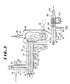
- FIG. 3 utilizes the same feed arrangement as that indicated in FIG. 1 comprising a feeding extruder 12 having an inlet 16 through which a paste 11 of the desired ingredients is introduced, a motor drive 18, and a shaft 20 driving a single screw 14 for injecting the paste into the reaction vessel 15' through opening 13'. Preheating is again provided through a heating system 17 to heat the ingredients prior to the reaction.
- the reaction occurs in two different reaction vessels, 15' and 82, rather than the single reaction vessel depicted in FIG. 1.
- the first portion of the reactor vessel 15' is identical to that of reactor 15 shown in FIG. 1 up to the point at which oxygen and vapor are vented through vent 34.
- reactor 15' comprises an extruder having co-rotating, intermeshing, fullywiped twin screws depicted by numerals 24' and 26' driven through two shafts 30' and 32' powered through motor 28', and heated by heating elements 23', 25', 27', each equipped with a controller 33'.
- holding tank 82 which is analogous to reactor 15' in that it is a high temperature, high pressure vessel. Both reactor 15' and tank 82 are maintained at essentially the same high pressure and temperature.
- Holding tank 82 is heated by heating element 29', and is equipped with vent 84 through which reaction byproducts such as oxygen and steam are vented via a control valve 86.
- holding tank 82 may be equipped with a stirring device, generally depicted by numeral 90, to provide for the agitation of the reaction ingredients during the residence time in the tank.
- the holding tank terminates in opening 92 which discharges into a combination reaction and pressure letdown extruder 98.
- Extruder 98 differs from the pressure letdown extruder shown in FIG. 1. It comprises two sections, a dry feed section which receives the material from the holding vessel 82, and a mixing and letdown section. An injection port 106 is provided at the end of the dry section through which water is injected. Following the point of water injection, a mixing section comprising mixing elements 102 is provided to thoroughly mix the dry reactive product with the injected water. Following mixing section 102 the pitch of the extruder screw is decreased to flood the remainder section 104 of the extruder and provide a plug seal for the eventual discharge of the product under atmospheric pressure. Valve 112 may be used to control this discharge and to release the product to a receiving container not indicated in this drawing.
- Extruder 98 further includes a motor drive 94 which operates the extruder screw through shaft 96.
- Heating means 31', with controller 33', are also provided in the dry section of this extruder.
- cooling means 110 are provided in the flooded section 104 of the extruder to reduce the temperature of the reacted material prior to discharge.
- Reaction temperature and pressure is maintained in the early section of the extruder and reacted product is advanced in a starved mode until the point where water is introduced to again produce the slurry necessary for the letdown process which occurs in the latter section of this extruder.
- cooling means 110 are provided for this latter section of the let- down extruder to bring the reaction material temperature close to room temperature at the discharge point.
- the continuous synthesis process of this invention is designed to operate continuously at a pressure of up to 41.4 MPa (6000 psi) and temperatures in excess of 350°C in a highly corrosive oxygen and chromic acid environment, with oxygen being a byproduct.
- the equipment must withstand such conditions, but also it must resist the abrasive action of the Cr0 2 product particles. Therefore, the selection of materials of construction, especially for the twin screw extruder, must be made with the above in mind.
- alloys containing nickel, molybdenum, aluminum or copper must be avoided as these elements tend to contaminate and lower the magnetic properties of the Cr0 2 .
- platinum, titanium, tantalum and iron are safe to use in the process. The following show good corrosion and abrasion resistance: Fe-14% Si, Ta-10%W (tungsten) alloys.
- a paste comprising a major amount of Cr0 3 /Cr 2 0 3 /H 2 0, and small amounts of Sb0 3 and Fe 2 0 3 was fed to a twin screw reactor extruder at the rate of 17 g/min at a temperature of 260°C and a pressure of 30.0 MPa (4350 psi).
- the paste was advanced through the reactor with a residence time of about 12 min at 29.6 MPa (4300 psi) (gas pressure).
Landscapes
- Chemical & Material Sciences (AREA)
- Organic Chemistry (AREA)
- Inorganic Chemistry (AREA)
- Inorganic Compounds Of Heavy Metals (AREA)
- Hard Magnetic Materials (AREA)
- Mixers Of The Rotary Stirring Type (AREA)
- Physical Or Chemical Processes And Apparatus (AREA)
Claims (8)
Applications Claiming Priority (2)
| Application Number | Priority Date | Filing Date | Title |
|---|---|---|---|
| US06/340,302 US4428852A (en) | 1982-01-18 | 1982-01-18 | Continuous synthesis of chromium dioxide |
| US340302 | 1982-01-18 |
Publications (2)
| Publication Number | Publication Date |
|---|---|
| EP0086042A1 EP0086042A1 (fr) | 1983-08-17 |
| EP0086042B1 true EP0086042B1 (fr) | 1986-03-26 |
Family
ID=23332765
Family Applications (1)
| Application Number | Title | Priority Date | Filing Date |
|---|---|---|---|
| EP83300220A Expired EP0086042B1 (fr) | 1982-01-18 | 1983-01-17 | Production continue du dioxyde de chrome |
Country Status (4)
| Country | Link |
|---|---|
| US (1) | US4428852A (fr) |
| EP (1) | EP0086042B1 (fr) |
| JP (1) | JPS58125615A (fr) |
| DE (1) | DE3362637D1 (fr) |
Families Citing this family (6)
| Publication number | Priority date | Publication date | Assignee | Title |
|---|---|---|---|---|
| US5342589A (en) * | 1992-09-22 | 1994-08-30 | Minnesota Mining And Manufacturing Company | Process for converting chromium dioxide magnetic pigment particles into nonmagnetic chromium (III) oxide |
| TW409383B (en) * | 1998-12-31 | 2000-10-21 | World Wiser Electronics Inc | Apparatus of plug hole process and the method thereof |
| GB2354471A (en) * | 1999-09-24 | 2001-03-28 | Univ Brunel | Producung semisolid metal slurries and shaped components therefrom |
| EP1534634A2 (fr) * | 2002-08-29 | 2005-06-01 | Tata Institute of Fundamental Research | Dioxyde de chrome (cro sb 2 /sb ), composites de dioxyde de chrome et d'autres oxydes de chrome, tels que cro sb 2 /sb /cr sb 2 /sb o sb 3 /sb et cro sb 2 /sb /cr sb 2 /sb o sb 5 /sb , et procede de production correspondant |
| US10624464B2 (en) * | 2019-07-11 | 2020-04-21 | Mohammed Shuaib | Double mattress connecting system |
| RU2754864C1 (ru) * | 2020-11-23 | 2021-09-08 | Акционерное общество «Обнинское научно-производственное предприятие «Технология» им. А.Г.Ромашина» | Способ получения неиспаряемого геттера и композитный геттер для рентгеновской трубки |
Family Cites Families (11)
| Publication number | Priority date | Publication date | Assignee | Title |
|---|---|---|---|---|
| US1379187A (en) | 1921-05-24 | Aiifonse kaufman | ||
| US2021991A (en) | 1933-06-19 | 1935-11-26 | American Zinc Lead & Smelting | Apparatus for the treatment of pigments |
| CH349583A (de) | 1956-03-06 | 1960-10-31 | Basf Ag | Einrichtung zur kontinuierlichen Umsetzung fester Stoffe |
| US3111394A (en) | 1959-03-13 | 1963-11-19 | Nuclear Materials & Equipment | Apparatus for treating chemical compounds |
| FR1294516A (fr) * | 1961-07-07 | 1962-05-26 | Hydrocarbon Mineralol G M B H | Procédé et dispositif pour produire des échanges de matière, des échanges d'énergie et des réactions |
| US3278263A (en) | 1964-11-27 | 1966-10-11 | Du Pont | Ferromagnetic chromium dioxide and preparation thereof |
| CH437217A (de) * | 1965-12-20 | 1967-06-15 | Buss Ag | Einrichtung zum kontinuierlichen Herstellen von Lösungen und Suspensionen |
| DE1542016A1 (de) * | 1966-06-27 | 1970-04-16 | Buss Ag | Verfahren zur Durchfuehrung von Hochtemperaturprozessen insbesondere bei Temperaturen ueber 300 deg. und Einrichtung zur Ausuebung des Verfahrens |
| US3991153A (en) | 1975-06-24 | 1976-11-09 | American Cyanamid Company | Single phase extrusion of acrylic polymer and water |
| US4045544A (en) | 1976-08-31 | 1977-08-30 | E. I. Du Pont De Nemours And Company | Process for the preparation of ferromagnetic chromium dioxide |
| DE2942646A1 (de) * | 1979-10-22 | 1981-04-30 | Basf Ag, 6700 Ludwigshafen | Verfahren zur herstellung von ferromagnetischem chromdioxid |
-
1982
- 1982-01-18 US US06/340,302 patent/US4428852A/en not_active Expired - Lifetime
-
1983
- 1983-01-17 DE DE8383300220T patent/DE3362637D1/de not_active Expired
- 1983-01-17 EP EP83300220A patent/EP0086042B1/fr not_active Expired
- 1983-01-17 JP JP58004283A patent/JPS58125615A/ja active Granted
Also Published As
| Publication number | Publication date |
|---|---|
| US4428852A (en) | 1984-01-31 |
| EP0086042A1 (fr) | 1983-08-17 |
| DE3362637D1 (en) | 1986-04-30 |
| JPS58125615A (ja) | 1983-07-26 |
| JPS6212175B2 (fr) | 1987-03-17 |
Similar Documents
| Publication | Publication Date | Title |
|---|---|---|
| US5114630A (en) | Continuous manufacture and casting | |
| US4275967A (en) | Method for the continuous production of explosive mixtures | |
| US6436326B1 (en) | Forming slurry of reactive components and continuously feeding into continuous reactor | |
| RU1780523C (ru) | Устройство дл непрерывного получени резиновой смеси | |
| US2733051A (en) | R street | |
| US4314963A (en) | Method and a device for producing shaped articles from a multi-component reaction mixture | |
| US9908261B2 (en) | Mixer, method of mixing raw material for powder metallurgy binder for injection moulding composition | |
| US4275033A (en) | Apparatus for producing a reaction mixture containing fillers from at least two components which are capable of flowing | |
| EP0086042B1 (fr) | Production continue du dioxyde de chrome | |
| US4861615A (en) | Methods for preparing chocolate mixtures | |
| CN101835584B (zh) | 用于制造聚合物颗粒的方法和装置 | |
| DE3537729C2 (de) | Vorrichtung zum Mischen und Pumpen einer spritzfähigen, feuerfesten Aufschlämmung | |
| CN112757642A (zh) | 螺杆式送料装置、用于3d打印的物料挤出系统和方法 | |
| EP4069486B1 (fr) | Methode et appareil pour produire en lots et appliquer en continu une composition refractaire sur une surface | |
| IE41241B1 (en) | Process for the production of elastomeric polyurethane ureas | |
| US2915299A (en) | Apparatus for controlling temperatures | |
| JPS62227909A (ja) | 合成物質製造方法及び装置 | |
| JPS61502784A (ja) | 合成樹脂の粘度測定方法および本法の実施装置 | |
| US4765745A (en) | Apparatus for dosing and mixing solids and liquids to form a low viscosity suspension | |
| JPS60120839A (ja) | テレフタル酸とエチレングリコ−ルとのスラリ−の連続供給法 | |
| US20010028937A1 (en) | Process for the preparation of a magnetic dispersion for magnetic recording media and magnetic recording media produced therewith | |
| CN120842119A (zh) | 一种连续动态管式反应工艺制备硝酸胍的方法 | |
| CA1099064A (fr) | Moulage de produits plastiques | |
| EP0264938B1 (fr) | Procédé pour préparer un matériau d'étanchéité de type monocomposant | |
| US4474957A (en) | Process for producing cyanuric acid from urea |
Legal Events
| Date | Code | Title | Description |
|---|---|---|---|
| PUAI | Public reference made under article 153(3) epc to a published international application that has entered the european phase |
Free format text: ORIGINAL CODE: 0009012 |
|
| AK | Designated contracting states |
Designated state(s): DE FR IT |
|
| 17P | Request for examination filed |
Effective date: 19831229 |
|
| GRAA | (expected) grant |
Free format text: ORIGINAL CODE: 0009210 |
|
| AK | Designated contracting states |
Kind code of ref document: B1 Designated state(s): DE FR IT |
|
| ITF | It: translation for a ep patent filed | ||
| REF | Corresponds to: |
Ref document number: 3362637 Country of ref document: DE Date of ref document: 19860430 |
|
| ET | Fr: translation filed | ||
| PLBE | No opposition filed within time limit |
Free format text: ORIGINAL CODE: 0009261 |
|
| STAA | Information on the status of an ep patent application or granted ep patent |
Free format text: STATUS: NO OPPOSITION FILED WITHIN TIME LIMIT |
|
| 26N | No opposition filed | ||
| ITTA | It: last paid annual fee | ||
| PGFP | Annual fee paid to national office [announced via postgrant information from national office to epo] |
Ref country code: FR Payment date: 19921210 Year of fee payment: 11 |
|
| PG25 | Lapsed in a contracting state [announced via postgrant information from national office to epo] |
Ref country code: FR Effective date: 19940930 |
|
| REG | Reference to a national code |
Ref country code: FR Ref legal event code: ST |
|
| PGFP | Annual fee paid to national office [announced via postgrant information from national office to epo] |
Ref country code: DE Payment date: 19991206 Year of fee payment: 18 |
|
| PG25 | Lapsed in a contracting state [announced via postgrant information from national office to epo] |
Ref country code: DE Free format text: LAPSE BECAUSE OF NON-PAYMENT OF DUE FEES Effective date: 20011101 |