EP0087091A2 - Petit meuble du type armoire - Google Patents
Petit meuble du type armoire Download PDFInfo
- Publication number
- EP0087091A2 EP0087091A2 EP83101364A EP83101364A EP0087091A2 EP 0087091 A2 EP0087091 A2 EP 0087091A2 EP 83101364 A EP83101364 A EP 83101364A EP 83101364 A EP83101364 A EP 83101364A EP 0087091 A2 EP0087091 A2 EP 0087091A2
- Authority
- EP
- European Patent Office
- Prior art keywords
- cover plate
- small
- furniture
- support column
- furniture according
- Prior art date
- Legal status (The legal status is an assumption and is not a legal conclusion. Google has not performed a legal analysis and makes no representation as to the accuracy of the status listed.)
- Withdrawn
Links
- 239000011521 glass Substances 0.000 abstract description 5
- 230000007704 transition Effects 0.000 description 3
- 238000003780 insertion Methods 0.000 description 2
- 230000037431 insertion Effects 0.000 description 2
- 238000004140 cleaning Methods 0.000 description 1
- 230000002093 peripheral effect Effects 0.000 description 1
- 230000000284 resting effect Effects 0.000 description 1
- 230000001960 triggered effect Effects 0.000 description 1
Images

Classifications
-
- A—HUMAN NECESSITIES
- A47—FURNITURE; DOMESTIC ARTICLES OR APPLIANCES; COFFEE MILLS; SPICE MILLS; SUCTION CLEANERS IN GENERAL
- A47B—TABLES; DESKS; OFFICE FURNITURE; CABINETS; DRAWERS; GENERAL DETAILS OF FURNITURE
- A47B69/00—Cocktail cabinets
-
- A—HUMAN NECESSITIES
- A47—FURNITURE; DOMESTIC ARTICLES OR APPLIANCES; COFFEE MILLS; SPICE MILLS; SUCTION CLEANERS IN GENERAL
- A47B—TABLES; DESKS; OFFICE FURNITURE; CABINETS; DRAWERS; GENERAL DETAILS OF FURNITURE
- A47B51/00—Cabinets with means for moving compartments up and down
-
- A—HUMAN NECESSITIES
- A47—FURNITURE; DOMESTIC ARTICLES OR APPLIANCES; COFFEE MILLS; SPICE MILLS; SUCTION CLEANERS IN GENERAL
- A47B—TABLES; DESKS; OFFICE FURNITURE; CABINETS; DRAWERS; GENERAL DETAILS OF FURNITURE
- A47B2200/00—General construction of tables or desks
- A47B2200/0035—Tables or desks with features relating to adjustability or folding
- A47B2200/004—Top adjustment
- A47B2200/0048—Concealable top fixed on a bedside table or similar
Definitions
- the invention relates to a box-shaped small piece of furniture with a cover plate closing the top of the furniture body.
- the known small pieces of furniture of this type are preferably used as occasional pieces of furniture in which the cover plate is firmly connected to the furniture body and the furniture body accommodates drawers or has lockable furniture compartments which can be operated or accessed from the front of the small piece of furniture.
- the upper region of the furniture body is designed as an upwardly open receiving compartment and in that the cover plate is attached to a vertical support column so that it can be adjusted in height.
- the cover plate on the furniture body can be raised so far that the storage compartment is easily accessible.
- the storage compartment can accommodate glasses, bottles and the like, which can be placed on the raised cover plate and are available at a height that enables easy removal and re-storage.
- Access to the storage compartment in the furniture body is improved in one embodiment in that the cover plate can be pivoted relative to the furniture body, at least in the extended position.
- the design can be such that the cover plate at the upper end of the support column is pivotable about a vertical axis of rotation, or that the cover plate is fixedly attached to the upper end of the support column and that the support column is vertically adjustable and rotatably mounted in the furniture body. In any case, the cover plate can be swung out so far that the storage compartment is exposed.
- the structural design of the small piece of furniture has advantageously shown a configuration which is characterized in that the support column is connected in a corner area to the underside of the cover plate and that the support column is arranged outside the storage compartment in a corner area of the furniture body. Moving the support column into a corner area of the furniture body makes it easier to accommodate and store the support column in the furniture body.
- An adjustment in the height of the adjusted cover plate allows an embodiment, which is characterized in that the support column is continuously extendable and lockable in any extension position by means of a locking device.
- the support column can be fixed in the extended end position by means of a latching device.
- a locking device is preferably used, which engages automatically when the pull-out end position is reached, but which must be triggered by means of a trigger member if the support column is to be pushed back into the furniture body.
- the receiving compartment is designed as a separate insert part, which is from the upper side can be inserted into the furniture body, then the storage compartment can be easily removed from the furniture body for cleaning.
- a further development of the small piece of furniture according to the invention is characterized in that the cover plate has a circumferential, raised plug-in edge on its top and that a tray can be plugged onto the cover plate, which carries a correspondingly recessed plug-in heel or plug-in web on its underside.
- the tray placed on the cover plate can first hold the glasses, bottles and the like removed from the storage compartment, then detached from the cover plate and placed in any place separate from the small furniture.
- the handling of the tray is facilitated in that the tray has recessed grips on its underside on two opposite sides, which are open towards the bottom and towards the outside. The recessed grips are delimited by means of sections of the plug-in web drawn in correspondingly to the middle of the tray.
- the tray is provided on its upper side with a circumferential raised edge which prevents the glasses, bottles and the like from slipping off the tray.
- cover plate has a shoulder on the underside which is circumferentially evenly set back relative to the outer contour of the cover plate and that The top of the furniture body has a raised heel that is flush with the outer contour of the heel on the underside of the cover plate in the inserted end position of the support column.
- the utilization of the space enclosed by the furniture body is improved in that drawers are arranged in the furniture body below the receiving compartment.
- the cross section of the furniture body is square with rounded corners. This configuration has the advantage that the tray can be connected to the cover plate in any position.
- Another expedient embodiment is characterized in that the furniture body is provided with rollers or the like and is designed to be mobile. The small piece of furniture can then easily be brought to the cheapest place.
- the furniture body 10 of the small piece of furniture according to FIG. 1 has a square cross section, the corners being rounded.
- the side parts 11 and 13 are partially led around the corners, so that 12 vertical, recessed grooves 14 are formed to the front wall, which strongly influence the aesthetic appearance.
- the two drawers 17 and 18 are accommodated, which are provided with lobed handles 19.
- the base 25, which is set back on all sides, closes the furniture body 10 at the bottom.
- a receiving compartment 16 is introduced, which is open towards the top.
- This storage compartment 16 is preferably formed by an insert part 15 which can be inserted into the furniture body 10 from the top and can be easily removed.
- the receiving compartment 16 leaves enough space in the corner areas of the furniture body 10 that a support column 20 can be installed which carries the cover plate 21 at the upper end.
- the support column 20 can be firmly connected to the cover plate 21, while the support column 20 is mounted in the furniture body 10 adjustable in height.
- the support column 20 can also be rotatably supported at the same time, so that the cover plate 21 can be pivoted out in the region of the receiving compartment 16, as shown in FIG. 1. It may be entirely sufficient if the cover plate 21 with the support column 20 is raised to the extended end position shown.
- a latching device can determine the final pull-out position. In this case, a latching device is preferred, which engages automatically, but has a separate, manually actuatable release member.
- the support column 20 can be rotated in the extended end position.
- the cover plate 21 at the upper end of the support column 20, which is only adjustable in height, so that it can itself pivot about a vertical axis of rotation.
- the support column 20 can be fixed in any pull-out position by means of a locking device of a known type and the height of the cover plate 21 can thus be adjusted.
- the cover plate 21 has a shoulder 24 on the underside, which is recessed all around uniformly with respect to the outer contour of the cover plate 21. This creates a recessed transition between the furniture body 10 and the cover plate 21 lowered onto the top of the furniture body 10, as shown in FIG. 2. This transition can be emphasized by the fact that the top of the furniture body 10 also carries a raised heel which is flush with the outer contour of the heel 24 on the underside of the cover plate 21 in the inserted position of the support column 20. It can be advantageous if the support column 20 can only be brought into the insertion position with the cover plate 21 when the cover plate 21 is pivoted in via the receiving compartment 16.
- the cover plate 21 has a circumferential raised plug edge 22 on the top, which delimits the storage area 23.
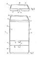
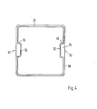
- the tray 30 according to FIGS. 3 and 4 can be connected to the cover plate 21.
- the tray 30 carries on its underside a plug-in web 31, the outer contour of which is adapted to the inner contour of the plug-in edge 22 of the cover plate 21, so that the tray 30 can be plugged onto the cover plate 21.
- the shelf 34 of the tray 20 is limited by the raised peripheral edge 33.
- the tray 30 On two sides opposite each other, the tray 30 has, on its underside, recessed grips 32 and 37 which are open to the outside and to the bottom. 4, the plug-in web 31 is drawn in toward the center of the tray 30, as can be seen in the sections 35, 36, 39 and 40 of the plug-in web 31. The edge 38 of the tray 30 remaining outside the plug-in web 31 limits the pushing-on movement of the tray 30 onto the cover plate 21, since this comes to rest on the plug-in edge 22 of the cover plate 21.
- the recessed grips 32 and 37 remain accessible so that the tray 30 can be easily lifted off the cover plate 21 again.
- the plug-in edge 22 of the cover plate 21 and the plug-in web 33 of the tray 30 are matched to a snug fit or press fit, so that the tray 30 is held sufficiently firmly on the cover plate 21.
- the tray 30 can also carry a shoulder with a corresponding outer contour on its underside, which can be inserted into the plug-in receptacle delimited by the plug-in rim 22 of the cover plate 21.
- the tray 30 is an independent component, the dimensions of which are matched to uniformly designed cover plates 21 of various small pieces of furniture, such as side cupboards, side tables or the like.
- the tray 30 can therefore be brought from one of these small pieces of furniture to another of these small pieces of furniture and placed or plugged there.
Landscapes
- Tables And Desks Characterized By Structural Shape (AREA)
- Legs For Furniture In General (AREA)
- Combinations Of Kitchen Furniture (AREA)
Applications Claiming Priority (2)
| Application Number | Priority Date | Filing Date | Title |
|---|---|---|---|
| DE19828204950 DE8204950U1 (de) | 1982-02-23 | 1982-02-23 | Kastenfoermiges kleinmoebel |
| DE8204950U | 1982-02-23 |
Publications (1)
| Publication Number | Publication Date |
|---|---|
| EP0087091A2 true EP0087091A2 (fr) | 1983-08-31 |
Family
ID=6737346
Family Applications (1)
| Application Number | Title | Priority Date | Filing Date |
|---|---|---|---|
| EP83101364A Withdrawn EP0087091A2 (fr) | 1982-02-23 | 1983-02-12 | Petit meuble du type armoire |
Country Status (3)
| Country | Link |
|---|---|
| EP (1) | EP0087091A2 (fr) |
| JP (1) | JPS58155808A (fr) |
| DE (1) | DE8204950U1 (fr) |
Cited By (4)
| Publication number | Priority date | Publication date | Assignee | Title |
|---|---|---|---|---|
| EP0252307A1 (fr) * | 1986-06-23 | 1988-01-13 | Linde Aktiengesellschaft | Meuble frigorifique |
| DE3738255C1 (en) * | 1987-11-11 | 1989-05-24 | Werner Schwienhorst | House bar |
| GB2262085A (en) * | 1991-12-04 | 1993-06-09 | Gary Singleton | Tool box |
| EP3226723A1 (fr) * | 2014-12-03 | 2017-10-11 | Grass GmbH & Co. KG | Dispositif de contrôle de déplacement d'une partie de meuble logée mobile sur un corps de meuble ainsi que meuble avec un tel dispositif |
-
1982
- 1982-02-23 DE DE19828204950 patent/DE8204950U1/de not_active Expired
-
1983
- 1983-02-12 EP EP83101364A patent/EP0087091A2/fr not_active Withdrawn
- 1983-02-18 JP JP2495583A patent/JPS58155808A/ja active Pending
Cited By (5)
| Publication number | Priority date | Publication date | Assignee | Title |
|---|---|---|---|---|
| EP0252307A1 (fr) * | 1986-06-23 | 1988-01-13 | Linde Aktiengesellschaft | Meuble frigorifique |
| DE3738255C1 (en) * | 1987-11-11 | 1989-05-24 | Werner Schwienhorst | House bar |
| GB2262085A (en) * | 1991-12-04 | 1993-06-09 | Gary Singleton | Tool box |
| GB2262085B (en) * | 1991-12-04 | 1995-07-19 | Gary Singleton | Improvements in and relating to a tool box |
| EP3226723A1 (fr) * | 2014-12-03 | 2017-10-11 | Grass GmbH & Co. KG | Dispositif de contrôle de déplacement d'une partie de meuble logée mobile sur un corps de meuble ainsi que meuble avec un tel dispositif |
Also Published As
| Publication number | Publication date |
|---|---|
| DE8204950U1 (de) | 1982-07-29 |
| JPS58155808A (ja) | 1983-09-16 |
Similar Documents
| Publication | Publication Date | Title |
|---|---|---|
| EP0222788B1 (fr) | Table a ecran de visualisation | |
| EP3294501A1 (fr) | Dispositif de rangement | |
| DE3506381C2 (fr) | ||
| EP0087091A2 (fr) | Petit meuble du type armoire | |
| DE1810003C3 (de) | Gehäuse für einen Plattenspieler | |
| DE4103786C2 (fr) | ||
| DE4108379C2 (de) | Schaltschrank mit Druckerauszug | |
| DE8204949U1 (de) | Bett mit ablageplatte | |
| DE4330926C2 (de) | Schaltschrank mit einem Schrankfach | |
| DE69104894T2 (de) | Bewegliches Gestell für Bauelemente. | |
| DE102005017701B3 (de) | Möbel | |
| DE3620016A1 (de) | Sammelbehaelter-kommode oder -einbauschrank | |
| DE19837725C1 (de) | Abfallsammler zum Einbau in ein Schrankmöbel | |
| DE20214166U1 (de) | Modularer Nachtschrank | |
| EP0284833A1 (fr) | Pupitre de lecture pliant | |
| DE2946681C2 (fr) | ||
| DE3742810C1 (en) | Cabinet compartment for accommodating implements | |
| DE3217269A1 (de) | Einbau-nachtkaestchen | |
| DE8505172U1 (de) | Schrankartiges Beistellmöbel, insbesondere für Computer-Arbeitsplätze | |
| DE661819C (de) | Ausziehtisch mit im Zargenrahmen oder in der Fusssaeule angeordneten Schubladen oderFaechern | |
| DE718283C (de) | Naehmaschinenschrankmoebel | |
| DE8331779U1 (de) | Kuechenschrank mit ausziehbarer tischplatte | |
| DE8900622U1 (de) | Gargerät mit Beschickungseinrichtung | |
| EP1253279A1 (fr) | Escabeau associé à un élément d'armoire | |
| DE6902391U (de) | Schreibmaschine mit koffer. |
Legal Events
| Date | Code | Title | Description |
|---|---|---|---|
| PUAI | Public reference made under article 153(3) epc to a published international application that has entered the european phase |
Free format text: ORIGINAL CODE: 0009012 |
|
| AK | Designated contracting states |
Designated state(s): BE DE FR IT NL SE |
|
| 17P | Request for examination filed |
Effective date: 19830906 |
|
| STAA | Information on the status of an ep patent application or granted ep patent |
Free format text: STATUS: THE APPLICATION IS DEEMED TO BE WITHDRAWN |
|
| 18D | Application deemed to be withdrawn |
Effective date: 19850828 |