EP0087307A2 - Temperaturüberwachungssysteme - Google Patents
Temperaturüberwachungssysteme Download PDFInfo
- Publication number
- EP0087307A2 EP0087307A2 EP19830300894 EP83300894A EP0087307A2 EP 0087307 A2 EP0087307 A2 EP 0087307A2 EP 19830300894 EP19830300894 EP 19830300894 EP 83300894 A EP83300894 A EP 83300894A EP 0087307 A2 EP0087307 A2 EP 0087307A2
- Authority
- EP
- European Patent Office
- Prior art keywords
- temperature
- signal
- conductors
- value
- cable
- Prior art date
- Legal status (The legal status is an assumption and is not a legal conclusion. Google has not performed a legal analysis and makes no representation as to the accuracy of the status listed.)
- Withdrawn
Links
Images

Classifications
-
- G—PHYSICS
- G08—SIGNALLING
- G08B—SIGNALLING SYSTEMS, e.g. PERSONAL CALLING SYSTEMS; ORDER TELEGRAPHS; ALARM SYSTEMS
- G08B17/00—Fire alarms; Alarms responsive to explosion
- G08B17/06—Electric actuation of the alarm, e.g. using a thermally-operated switch
Definitions
- This invention relates to temperature monitoring systems.
- a known type of temperature monitoring system particularly (but not exclusively) useful for detecting fires, includes a cable arrangement comprising at least two conductors, two at least of the conductors being separated by elongate temperature-sensitive means, and detection means for monitoring the shunt impedance (or a component thereof) between the conductors separated by the temperature-sensitive means.
- a cable arrangement comprising at least two conductors, two at least of the conductors being separated by elongate temperature-sensitive means, and detection means for monitoring the shunt impedance (or a component thereof) between the conductors separated by the temperature-sensitive means.
- Such systems may be of two types, depending upon whether the cable arrangement comprises what is known in the art as a "digital cable” or what is known in the art as an "analogue cable".
- the temperature-sensitive means comprises an electrically insulative material that melts (liquifies or softens) in the event of a fire or other overheat situation to allow contact of the conductors, whereby the above-mentioned impedance is subjected to a large abrupt change from one value to another in response to the overheat.
- the temperature-sensitive means has an impedance that varies in an analogue manner with temperature whereby monitoring of the impedance can produce a signal that is representative of the temperature of the cable arrangement.
- the ambient temperature of the cable arrangement generally has a significant effect on the operation of the system and it is thus often desirable reliably to monitor the ambient temperature, e.g. to provide a continuous indication of such temperature or to indicate to supervisory or operating personnel and/or equipment that the temperature has gone beyond a predetermined limit or limits. Reliable monitoring of the ambient temperature may be difficult, bearing in mind in particular that it may vary along the length of the cable arrangement.
- a temperature monitoring system comprising:
- the ambient temperature can be monitored by using the cable arrangement itself as a sensor.
- the ambient temperature can thus be monitored reliably and accurately, in contrast for example to the case in which one or more point measurements are relied upon.
- the second-mentioned means for monitoring is.preferably operative to monitor - wholly or predominantly - the resistance between the ends of the series circuit.
- the second-mentioned monitoring means may be operative to monitor, at one end of the cable arrangement, the series resistance of a series circuit comprising two conductors connected together at the other end of the cable arrangement to form a looped conductor.
- the second-mentioned monitoring means may be operative to monitor the resistance of a series circuit comprising one conductor and an earth return.
- the first-mentioned monitoring means is operative to indicate a fire or other overheat situation and the second-mentioned monitoring means is operative separately to indicate when the ambient temperature exceeds a value - e.g. a permitted maximum ambient - somewhat less than the value necessary to cause the first-mentioned monitoring means to indicate a fire or other overheat.
- the detection and monitoring means use output signals that' are employed interactively.
- the means for monitoring the shunt impedance is generally operative to provide an output signal if the impedance of the temperature sensitive means achieves a threshold value indicative of the cable being at a predetermined temperature.
- the elongate temperature-sensitive means may for example comprise polyvinyl chloride (PVC) which has a negative temperature coefficient such that at room temperature it acts as an insulator and such that its impedance drops with increasing temperature in a known manner.
- PVC polyvinyl chloride
- the impedance between the conductors, for a given length of cable will decrease as the temperature increases. Looking at the matter in another way, the impedance between the conductors, for a given temperature, will decrease as the length of the cable increases.
- the impedance of a short piece of cable at a given temperature is the same as that of a longer piece of cable at a lower temperature.
- the system is designed to provide an output signal (hereinafter also referred to as 'an alarm') if the impedance is such that any one metre length of the cable is at 100°C, for example due to the cable being heated by a fire.
- 'an alarm' an output signal
- the limit could in principle be increased by making the monitoring means respond to a lower threshold shunt impedance, e.g. to provide an alarm only if one metre of the cable is heated to an operating or trip temperature of greater than 100°C.
- increasing the limit in this way is not acceptable since to do so to any substantial extent would mean that the temperature value to which a short length of the cable has to be heated to cause an alarm would be unacceptably high.
- the maximum length of the cable that can be employed in the known system if both spurious alarms due to ambient temperature rises and an unacceptably high operating or trip temperature for heating of a short length of the cable are to be avoided.
- the maximum length of cable that can be employed is dictated by the differential between the required operating or trip temperature and the maximum ambient temperature.
- the differential between the required operating or trip temperature and the maximum ambient temperature it might be necessary to split that length into several sub-lengths each provided with its own detection means and associated circuitry thereby increasing cost and complexity.
- a trade-off or compromise must be made between the maximum length of cable that can be employed and the differential between the maximum ambient temperature and the operating or trip temperature.
- the elongate temperature-sensitive means has an impedance that varies with temperature
- the system comprises:
- the at least partial compensation for ambient temperature changes provided by such a system relaxes the above-described constraint on the maximum cable length in that the differential between the ambient temperature and the operating or trip temperature is constrained and is in fact preferably held constant at least over a certain range of ambient temperatures.
- This advantage is achieved in essence by monitoring and suitably compensating for the ambient temperature by monitoring the impedance (or a component thereof) of the series circuit comprising the at least one conductor.
- the ambient temperature is measured reliably and accurately, in marked contrast to what might be the case if, for example, an attempt was made to provide compensation for ambient temperature changes by means of one or more point measurements of ambient temperature.
- the second signal is preferably wholly or predominantly representative of the resistance of the conductor or conductors concerned.
- the second signal thus reacts in a totally different way to local heating than does the first signal, in that the first signal is representative of the shunt impedance (or a component thereof) between the conductors separated by the temperature-sensitive means and will thus vary markedly in response to local overheating since local overheating can be considered to change markedly the impedance of what can be considered to be one of a plurality of incremental impedors connected in parallel. That is . to say, the second signal can be considered, at least approximately, to vary only with general heating of the cable arrangement due to ambient changes, taking little or no notice of local changes due to a localised fire or the like, whereby the second signal provided in such a case is very well suited to compensate for ambient temperature changes.
- the above-mentioned compensation means may include means operative to vary the relationship between the second signal and the reference value in a sense complementary to that in which the first signal varies with temperature, assuming that both such signals do not vary with temperature in the same way.
- the compensation means may comprise a converter that provides a generally logarithmic transfer function between the second signal and the reference value.
- the ambient temperature of the cable arrangement could rise gradually to a dangerous value.
- the temperature monitoring system could conceivably not respond at all to the fire but instead treat the slowly rising temperature as a slowly rising permissible ambient temperature and do nothing to provide an output signal.
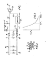
- the temperature monitoring system shown in Figure 1 includes an "analogue" temperature monitoring cable 10 comprising four wires 12 that are twisted together and, preferably, enclosed within a sheath (not shown). (The cable 10 could however be of coaxial construction). The cable 10 is disposed in proximity to an object or an area whose temperature is to be monitored, e.g. above a conveyor belt or on a ceiling, in particular to detect a fire.
- the wires 12 comprise respective conductors 14, 16, 18 and 20 having respective sheaths 22.
- the sheaths 22 are of a material of which the impedance (or a component thereof) has a temperature coefficient, for example a negative temperature coefficient.
- the material can be silicone rubber or a form of rubber known in the art as "EP rubber".
- the material is polyvinyl chloride (PVC), which may or may not be doped with a material that enhances its conductivity.
- PVC polyvinyl chloride
- the resistance of PVC whether doped or undoped, drops from a very high value at room temperature, in a substantially logarithmic value, as its temperature increases.
- the wires 12 having the conductors 14,16 are joined at one end of the cable 10 (the left hand end as shown in Figure 1) - or comprise a single wire folded back on itself - thereby to form a single looped conductor 24 whose ends are accessible at the other end of the cable 10.
- the wire ⁇ 12 having the conductors 18,20 are joined - or integral - at the left hand end of' the cable 10 as shown in Figure 1 to form another looped conductor 26.
- the looped conductors 24, 26 are useful for a number of reasons, especially in that they enable the continuity of the wiring to be checked by checking that the loops are not broken. However, at least one of the loops is used for a further purpose, the nature of which will be explained below.
- the wires 12 are shown in Figure 2 as being so arranged that the conductors forming each of the looped conductors 24, 26 are diagonally opposite each other. They could instead be arranged with such conductors adjacent each other.
- the looped conductors 24 and 26 are separated by the temperature-sensitive material constituting the sheaths 22.
- the distributed shunt impedance of the sheaths 22 between the conductors 24 and 26 is shown in Figure 1 as comprising a plurality of discrete resistors connected in parallel, the total resistance thereof as viewed at the ends of the cable being R s .
- Figure 1 should, strictly speaking, show further discrete resistors connected between the conductors 14 and 18 and the conductors 16 and 20. However, for convenience, these are omitted.
- a resistor R is connected between a +V rail 30 and the looped conductor 24. An 0V rail is connected to the conductor 26.
- the resistor R and the resistance R are connected in series across a d.c. voltage source +V whereby the voltage on a line 32 connected to the junction of the resistor R and the resistance R constitutes a signal representing the value of the shunt resistance R s .
- This voltage is applied to one input of a comparator 34.
- a reference value or signal is applied on a line 36 to another input of the comparator 34 and the comparator 34 is operative to produce an output signal on an output terminal 38 when the resistance R drops to a value indicating that the temperature of the cable 10 has exceeded a predetermined trip or threshold value.
- the resistance R can be considered as being constituted by a multiplicity of incremental resistance elements connected in parallel, the resistance R s could drop to the value causing the generation of an output signal either by general heating of the whole cable 10 or by more intense localised heating of a part of the cable 10.
- a current source 40 is connected as shown to the looped conductor 26 and to the +V rail 30 and OV rail such that a predetermined d.c. current is sent through the looped conductor 26.
- the current source 40 could be a constant current source, but preferably comprises simply a resistor whose resistance is high with respect to that of the looped conductor 26 whereby the predetermined d.c.current is substantially unaffected by changes in the resistance of the conductor 26).
- the looped conductor 26 is of a material whose resistance changes in known manner with temperature. The material may for example be copper, whose resistance changes by approximately 0.4% per deg C and in fact increases by a factor of only about two between normal ambient temperature and its melting point.
- the voltage (with respect to the OV rail) on a line 42 will be representative of the resistance of the looped conductor 26. That is to say, such voltage will vary with changes in the ambient temperature of the cable 10. Note, however, that since the resistance of the loop 26 can be considered to be the series combination of a multiplicity of incremental resistance elements, the overall resistance of the looped conductor 26 will be subjected only to a small change if the cable 10 is subject to intense local heating as a result of a localised fire.
- the relationship between R s and temperature is approximately linear, there being typically a 17 deg C change in temperature per decade of resistance or, in other words, a doubling or halving of resistance for a change in temperature typically of about 5 deg C.
- the magnitude of the signal on the line 32 representing the parameter R will vary in similar manner, though not in exactly the same manner because R forms a potential divider chain with the resistor R.
- the signal on the line 42 which represents the series resistance of the looped conductor, is processed by a converter or amplifier 44 which has a logarithmic characteristic or transfer function such as to produce from the signal on the line 42 a modified (reference) signal on the line 36 which varies with temperature in similar manner to that on the line 32.
- the signal on the line 36 provides a degree of ambient temperature compensation for the signal on the line 32, in that both signals vary in a similar manner with changes in the ambient temperature of the cable 10, but does not preclude the generation of an output signal on the terminal 38 in the event of a fire situation in that the reference signal on the line 36, unlike that on the line 32, does not respond substantially to le g alised heating, for the reasons explained above.
- sample and hold units may be incorporated in the converter 44 and in the line 32 to sample the lines 42 and 32 at the appropriate times.
- d.c. energisation of both the resistance R and the conductor 26 is employed.
- a form of pulse energisation described below may also be used.
- the converter 44 can be arranged so that it does not continue to alter the reference value if the signal on the line 42 goes beyond a value equivalent to a limit temperature value of, say, 32 deg C greater than a predetermined temperature value equal, for example, to a normal ambient temperature value. Looking at the matter another way, the converter 44 causes the system to cease to preserve the fixed differential between the ambient temperature and alarm temperature - i.e. to stop the alarm temperature tracking the ambient temperature - once the ambient temperature exceeds said limit temperature value.
- the converter 44 may in fact be designed so that it does not provide a continuously varying output but instead provides an output which can adopt only one of (say) eight discrete values each corresponding to the signal on the line 42 indicating a respective step in temperature of (say) 4 deg C above said predetermined temperature value (e.g. normal ambient temperature value).
- a predetermined temperature value e.g. normal ambient temperature value
- FIG. 4 A modified temperature monitoring system embodying the invention will now be described with reference to Figure 4.
- the system of Figure 4 is closely based upon that of Figure 1 and will only be described in so far as it differs therefrom.
- the system of Figure 4 incudes a feature, more fully described in our co-pending UK Patent Application No. 8205338 and in our co-pending European patent application of even date herewith, which avoids certain disadvantages that may be incurred if the resistance R is energised with direct current.
- an electronic switch arrangement 50 is provided in the system of Figure 4.
- the switch arrangement 50 is operative so that the current sent through the resistance R is periodically reversed at a frequency corresponding to the frequency of switching thereby to reduce the net d.c.current, preferably to zero.
- operation of the switching arrangement 50 would have no affect on the signal on the line 32.
- the cable 10 has considerable capacitance, there is in fact a spike on the signal on the line 32 each time the current is reversed due to the capacitance of the cable being charged.
- the resultant waveform on the line 32 is as shown in Figure 4.
- the switching frequency of the switching arrangement 50 which is determined by control logic 52 driven by a clock 54, is chosen to be sufficiently slow that the cable capacitance charges in good time for the signal on the line 32 to reach a steady state value before the next current reversal.
- the necessary frequency will of course vary with different materials and different applications, though a typical frequency will be about 1/6 or 1/7 Hz, that is to say the period of the waveform will about 6 or 7 seconds in such a typical application.
- a sample and hold unit 56 is provided in the line 32 to sample the waveform during each 'plateau' portion, i.e. after the end of each spike.
- the control logic 52 also controls and synchronises a gate 58 such that current is sent through the looped conductor 26 towards the end of each plateau of the waveform on the line 32, i.e. shortly before the next spike.
- the converter 44 will include a sample and hold unit or the like to sample the resultant voltage on the line 42 at the appropriate times, but may otherwise be of the same construction decribed above.
- the circuit of Figure 4 in fact operates in much the same manner as that of Figure 1, as regards the feature of temperature compensation, the only substantial difference being that, as mentioned above, the resistance R s is periodically energised by d.c. of opposite polarity whereby problems associated with continuous energisation with the same polarity can be avoided or at least reduced.
- control logic 52 may comprise an edge-triggered counter/divider driven by the clock 54 to produce an output switching waveform whose two halves are of exactly equal time span.
- the invention can of course be embodied in various different ways than those described above by way of example.
- a.c. energisation can in principle be used instead of d.c. energisation.
- the parameter measured instead of measuring R , the parameter measured might be the impedance of the sheaths 22. Over a large range of frequencies the impedance would in fact be largely or predominately resistive, in particular if the PVC is doped with a conductivity-enhancing material. However, the capacitive component may have some affect at high frequencies, in particular if undoped PVC is used.
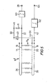
- FIG. 5 Another temperature monitoring system embodying the invention is shown in Figure 5.
- the system of Figure 5 resembles that of Figure 1 to some extent and will therefore be described only in so far as it differs therefrom.
- the system of Figure 5 includes a cable 10 * which, for convenience, is illustrated as having a like configuration to the cable 10, though it should be appreciated that - as explained below - other forms of cable can readily be employed.
- the cable 10' differs from the cable 10 in that it is a digital rather than an analogue cable.
- the material of the wire sheaths 22, represented by the resistance R does not necessarily have a temperature coefficient of resistance, since in this embodiment the arrangement is such that, in the event of a fire or the like, the material melts (liquefies or softens) to allow contact of the at least one of the conductors 14, 16 with at least one of the conductors 18, 20, the resultant short circuit resulting in R s dropping from a very high to a low value.
- Means is provided to provide an alarm output signal on the output terminal 38 when the resistance R drops to a low value as a result of a fire or the like.
- the resistance R and the resistor R are connected in series as a potential divider across the +V d.c. supply and their junction is connected to an input of a trigger circuit 60, the circuit 60 being operative to provide an alarm output signal when it detects that the voltage on the line 32 has dropped from a relatively high level to a relatively low level as a result of the resistance R s having done likewise.
- the signal on the line 42 is representative (in an analogue sense) of the resistance of the looped conductor 26 and therefore of the ambient temperature of the cable 10'.
- Such signal is applied to an input of a trigger circuit 62 set to switch and provide a warning output signal on an output terminal 64 if the ambient temperature exceeds a predetermined value, e.g. maximum permitted value.
- the parameter of the loop 26 that is monitored may not be its resistance. It is contemplated that a cable might be provided in which the inductance of the loop 26 might vary with temperature, in which case the inductance could be monitored and used to provide an indication of the ambient temperature.
- a device having a different characteristic for positive and negative polarities e.g. a diode
- This can enable different properties of the cable arrangement to be measured by reversing the polarity of energisation.
- the shunt-impedance detection means in effect monitors the shunt impedance (or a component thereof) between the two conductors when the polarity is such that the diode does not conduct.
- the diode With the opposite polarity, the diode is forward-biased whereby the diode effectively short-circuits the remote ends of the conductors together and enables their continuity to be checked by measuring the resistance presented to the detection means. If the conductors monitored by the shunt-impedance detection means and the series-circuit impedance monitoring means are common, e.g. if there are only two conductors, the continuity check can be carried out by the monitoring means monitoring the impedance (e.g. resistance) of the two conductors. That is to say, the impedance of the temperature-sensitive means is monitored when the energisation is of one polarity (e.g.
Landscapes
- Business, Economics & Management (AREA)
- Emergency Management (AREA)
- Physics & Mathematics (AREA)
- General Physics & Mathematics (AREA)
- Fire-Detection Mechanisms (AREA)
Applications Claiming Priority (2)
| Application Number | Priority Date | Filing Date | Title |
|---|---|---|---|
| GB8205339 | 1982-02-23 | ||
| GB8205339 | 1982-02-23 |
Publications (1)
| Publication Number | Publication Date |
|---|---|
| EP0087307A2 true EP0087307A2 (de) | 1983-08-31 |
Family
ID=10528554
Family Applications (1)
| Application Number | Title | Priority Date | Filing Date |
|---|---|---|---|
| EP19830300894 Withdrawn EP0087307A2 (de) | 1982-02-23 | 1983-02-21 | Temperaturüberwachungssysteme |
Country Status (1)
| Country | Link |
|---|---|
| EP (1) | EP0087307A2 (de) |
Cited By (4)
| Publication number | Priority date | Publication date | Assignee | Title |
|---|---|---|---|---|
| FR2598239A1 (fr) * | 1986-05-01 | 1987-11-06 | Gen Electric | Dispositif de detection de chaleur et/ou de fumee |
| US4707686A (en) * | 1986-04-03 | 1987-11-17 | General Electric Company | Over temperature sensing system for power cables |
| US5015958A (en) * | 1983-06-30 | 1991-05-14 | Raychem Corporation | Elongate sensors comprising conductive polymers, and methods and apparatus using such sensors |
| CN113196023A (zh) * | 2018-12-21 | 2021-07-30 | 诺沃皮尼奥内技术股份有限公司 | 具有saw或baw装置的涡轮机、测量布置结构和安装方法 |
-
1983
- 1983-02-21 EP EP19830300894 patent/EP0087307A2/de not_active Withdrawn
Cited By (4)
| Publication number | Priority date | Publication date | Assignee | Title |
|---|---|---|---|---|
| US5015958A (en) * | 1983-06-30 | 1991-05-14 | Raychem Corporation | Elongate sensors comprising conductive polymers, and methods and apparatus using such sensors |
| US4707686A (en) * | 1986-04-03 | 1987-11-17 | General Electric Company | Over temperature sensing system for power cables |
| FR2598239A1 (fr) * | 1986-05-01 | 1987-11-06 | Gen Electric | Dispositif de detection de chaleur et/ou de fumee |
| CN113196023A (zh) * | 2018-12-21 | 2021-07-30 | 诺沃皮尼奥内技术股份有限公司 | 具有saw或baw装置的涡轮机、测量布置结构和安装方法 |
Similar Documents
| Publication | Publication Date | Title |
|---|---|---|
| US4453159A (en) | Self-monitoring heat tracing system | |
| CN102037338B (zh) | 在空间检测范围内的地点分辨的温度测量 | |
| US4361799A (en) | Over-temperature sense and locate device | |
| US11733276B2 (en) | Power line sag monitoring device | |
| HU211049B (en) | Method and arrangement for measuring internal impedance of alternative current power supply unit | |
| EP1777671A1 (de) | Überwachung der Verdrahtung eines Alarmsystems | |
| EP2704267A2 (de) | Schiebering- und elektrisches Schieberingsystem | |
| EP0076586A1 (de) | In Kaskade geschaltete Überwachungseinrichtung | |
| SE462244B (sv) | Elektrodlinjeskydd foer detektering av jordfel | |
| CN107545692B (zh) | 不可恢复式缆式线型感温火灾探测器 | |
| AU2024202610B2 (en) | Cable network power unit for surge protector release | |
| EP0087307A2 (de) | Temperaturüberwachungssysteme | |
| EP0530012B1 (de) | Anordnung für Wärme-Sensorkabel und Kabel dafür | |
| EP3548855A1 (de) | Verkürzte thermoelementdiagnostik | |
| US4639719A (en) | Apparatus for monitoring circuit integrity | |
| EP0418321B1 (de) | System und verfahren zur detektierung und lokalisierung von flüssigkeits-leckstellen | |
| EP0087308A2 (de) | Temperaturüberwachungssysteme | |
| EP0656533B1 (de) | Vorrichtungen und Verfahren zur Temperaturdetektion | |
| JP7724293B2 (ja) | 電気ケーブル間のコネクタにおける発熱を検出するシステム | |
| CN210777039U (zh) | 一种短路时报火警的缆式线型感温火灾探测器 | |
| US4172252A (en) | Monitoring arrangement for monitoring a change from a normal condition of any one of a plurality of condition sensing devices | |
| CN201203924Y (zh) | 一种不可恢复式缆式线型感温火灾探测器 | |
| US4411536A (en) | Bi-directional temperature excursion sensing and locating apparatus | |
| EP0011461A1 (de) | Ein verbessertes Feuerdetektionssystem | |
| EP0160440A1 (de) | Vorrichtung zur Feststellung und zum Erhalt von Information über Änderungen von Variablen |
Legal Events
| Date | Code | Title | Description |
|---|---|---|---|
| PUAI | Public reference made under article 153(3) epc to a published international application that has entered the european phase |
Free format text: ORIGINAL CODE: 0009012 |
|
| AK | Designated contracting states |
Designated state(s): CH DE FR GB IT LI NL |
|
| STAA | Information on the status of an ep patent application or granted ep patent |
Free format text: STATUS: THE APPLICATION HAS BEEN WITHDRAWN |
|
| 18W | Application withdrawn |
Withdrawal date: 19840924 |
|
| RIN1 | Information on inventor provided before grant (corrected) |
Inventor name: SANDERS, PAUL OWEN Inventor name: NAILOR, ROY FREDERICK |