EP0076586A1 - In Kaskade geschaltete Überwachungseinrichtung - Google Patents
In Kaskade geschaltete Überwachungseinrichtung Download PDFInfo
- Publication number
- EP0076586A1 EP0076586A1 EP82304906A EP82304906A EP0076586A1 EP 0076586 A1 EP0076586 A1 EP 0076586A1 EP 82304906 A EP82304906 A EP 82304906A EP 82304906 A EP82304906 A EP 82304906A EP 0076586 A1 EP0076586 A1 EP 0076586A1
- Authority
- EP
- European Patent Office
- Prior art keywords
- transducer
- logic
- module
- wire
- section
- Prior art date
- Legal status (The legal status is an assumption and is not a legal conclusion. Google has not performed a legal analysis and makes no representation as to the accuracy of the status listed.)
- Withdrawn
Links
- 238000012544 monitoring process Methods 0.000 title claims abstract description 38
- 238000012546 transfer Methods 0.000 claims description 6
- 230000004044 response Effects 0.000 claims description 3
- 230000003213 activating effect Effects 0.000 abstract description 2
- 238000005259 measurement Methods 0.000 description 23
- 230000001419 dependent effect Effects 0.000 description 4
- 238000010586 diagram Methods 0.000 description 4
- 238000000034 method Methods 0.000 description 4
- 230000008569 process Effects 0.000 description 4
- 230000008901 benefit Effects 0.000 description 3
- 230000004913 activation Effects 0.000 description 2
- 238000004891 communication Methods 0.000 description 2
- 230000005669 field effect Effects 0.000 description 2
- 230000006870 function Effects 0.000 description 2
- 230000035945 sensitivity Effects 0.000 description 2
- 230000001133 acceleration Effects 0.000 description 1
- 239000004020 conductor Substances 0.000 description 1
- 230000003247 decreasing effect Effects 0.000 description 1
- 230000002262 irrigation Effects 0.000 description 1
- 238000003973 irrigation Methods 0.000 description 1
- 238000013021 overheating Methods 0.000 description 1
- 238000012545 processing Methods 0.000 description 1
- 230000000087 stabilizing effect Effects 0.000 description 1
- 230000000153 supplemental effect Effects 0.000 description 1
- 230000002123 temporal effect Effects 0.000 description 1
- 230000007704 transition Effects 0.000 description 1
- 238000009966 trimming Methods 0.000 description 1
Images

Classifications
-
- H—ELECTRICITY
- H04—ELECTRIC COMMUNICATION TECHNIQUE
- H04L—TRANSMISSION OF DIGITAL INFORMATION, e.g. TELEGRAPHIC COMMUNICATION
- H04L12/00—Data switching networks
- H04L12/28—Data switching networks characterised by path configuration, e.g. LAN [Local Area Networks] or WAN [Wide Area Networks]
- H04L12/40—Bus networks
- H04L12/40006—Architecture of a communication node
- H04L12/40013—Details regarding a bus controller
-
- H—ELECTRICITY
- H04—ELECTRIC COMMUNICATION TECHNIQUE
- H04L—TRANSMISSION OF DIGITAL INFORMATION, e.g. TELEGRAPHIC COMMUNICATION
- H04L12/00—Data switching networks
- H04L12/28—Data switching networks characterised by path configuration, e.g. LAN [Local Area Networks] or WAN [Wide Area Networks]
- H04L12/40—Bus networks
- H04L12/403—Bus networks with centralised control, e.g. polling
-
- H—ELECTRICITY
- H04—ELECTRIC COMMUNICATION TECHNIQUE
- H04Q—SELECTING
- H04Q9/00—Arrangements in telecontrol or telemetry systems for selectively calling a substation from a main station, in which substation desired apparatus is selected for applying a control signal thereto or for obtaining measured values therefrom
-
- H—ELECTRICITY
- H04—ELECTRIC COMMUNICATION TECHNIQUE
- H04Q—SELECTING
- H04Q2209/00—Arrangements in telecontrol or telemetry systems
- H04Q2209/10—Arrangements in telecontrol or telemetry systems using a centralized architecture
-
- H—ELECTRICITY
- H04—ELECTRIC COMMUNICATION TECHNIQUE
- H04Q—SELECTING
- H04Q2209/00—Arrangements in telecontrol or telemetry systems
- H04Q2209/70—Arrangements in the main station, i.e. central controller
- H04Q2209/75—Arrangements in the main station, i.e. central controller by polling or interrogating the sub-stations
Definitions
- Pipelines are often heated to keep the contents from solidifying, so knowledge of the pipe temperature at a large number of points is quite useful.
- Telephone cables are often pressurized to keep moisture out, so knowledge of the pressure at a number of locations within the cable is of great value.
- Land is often fenced for security measures and knowledge of the fence motion at a large number of points can indicate the presence of intruders.
- Proper ground moisture is important for the growth of agricultural crops and knowledge of the ground moisture level at numerous locations is important for intelligent control of irrigation equipment. Of course there are many other examples of extended or spatially distributed structures or equipment where knowledge of physical parameters measured at a great many location is useful.
- Remote sensors typically utilize one or more wire pairs for connection to a central control room.
- the result is a great many wire pairs with attendant harnessing, connectors, conduit, expense, etc.
- Recent electronic advances have sought to alleviate excessive wiring through the use of multiplexing whereby one wire pair or co-axial cable connects numerous remote sensors, but these systems have disadvantages in terms of the size and cost of the addressable modules.
- the present invention utilizes a relatively small number of conductors (wires) to connect a large number of relatively small, inexpensive, remote monitoring modules without multiplex address module circuitry or individual module wire pairs or electromechanical module components or voltage operated module components.
- the present invention provides an apparatus for monitoring a value of at least one physical parameter at a plurality of points, comprising:
- the apparatus of this invention can thus be used for monitoring one or more physical parameters at a number of locations and utilizing the values of the parameters for monitoring purposes at a common location, and can be arranged with advantage to be economical and to provide a monitoring apparatus which is easily modified, spliced, branched, or repaired in the field, which can be used in great lengths and is relatively insensitive to electromagnetic interference and other extraneous influences, and which utilizes remote monitoring modules of relatively small size and low cost.
- the apparatus may be arranged to monitor a desired physical parameter with a series of identical modules, or monitor different physical parameters wherein each physical parameter is monitored by a set of identical modules.
- the apparatus of the present invention may be arranged to produce alarm and control signals when the value of the physical parameter measured at any remote location extends beyond preset levels.
- Each monitoring module includes a logic section and a transducer section which converts the value of the sensed physical parameter at that location to an electrical signal.
- the master electronics reads the output of all the transducer sections sequentially. The master electronics sends a logic signal to the first monitoring module. The logic section receives the logic signal and subsequently activates its associated transducer section. The activated transducer communicates its signal to the master electronics. The electrical signal is utilized by the master electronics for monitoring purposes and the master electronics may correct the measurement for known transducer errors and perform computations and comparisons as well as display the information.
- subsequent clock pulses transfer the logic signal to the next module.
- each logic section sequentially receives the logic signal, thereby repeating the above-described process.
- the logic signal is received by the master electronics and the process begins again.
- two clock pulses may be utilized to transfer the logic signal between adjacent modules. This is done to create a zero output dead band on the measurement wire between the electrical output of each of the transducer. This enables the master electronics to count dead bands and keep a running count of which module is activated. Counting dead bands provides a means of identifying which module is activated without relying solely on counting clock pulses.
- the master electronics includes a clock which sends a clock pulse to all modules simultaneously.
- the clock pulse causes the high or low logic signal at the input to every module to advance to within the module and causes the high or low logic signal within the module to advance to the output of the module and hence to the input of the succeeding module.
- Use of a clock is desirable because the rate of propagation of the logic signal down the cable is controlled by the master electronics and can be changed as required.
- the clock frequency is determined by a trade-off between the need to measure the electrical output of the transducer for a long enough time to get an accurate value (independent of electrical noise) and still interrogate all modules quickly enough to detect significant temporal changes in the parameters of interest. Counting clock pulses and dividing by two also gives the location of the module containing the activated transducer.
- the invention may include an additional wire called a branch line to aid in branching and otherwise modifying the monitoring apparatus in the field.
- the transducer signal will preferably be of such form that it may be received along the same wire by the master electronics, but it will be appreciated that a number of different lines could be used if the electrical signals from the transducer were of incompatible forms.
- the monitoring apparatus in accordance with this invention may use relatively low cost transducers which have a wide tolerance range. It is not necessary for the carrying out of this invention that the transducers be particularly accurate or within a narrowly defined tolerance range because the structure of the apparatus provides for the use of wide tolerance, low cost transducers.
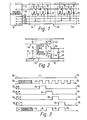
- figure 1 illustrates in schematic form, a six wire embodiment of the monitoring apparatus in accordance with this invention generally denoted by the numeral 10.
- the cable includes a voltage wire 12, a data wire 14, a clock wire 16, a measurement wire 18, a common wire 20 and a branch wire 22.
- the apparatus 10 further includes a plurality of modules 24, each having logic sections generally denoted by the numeral 26, which in this embodiment comprises two type D flip-flops 28 and 30 and a transducer section 32.
- the module 24 is typical of many such modules attached to the six wire cable embodiment to provide the monitoring function of the instant invention. All of the wires are continuous except the data wire 14 which is broken at each module 24 so that the information on the data wire 14 must traverse the module itself.
- the flip-flops 28 and 30 are commercially available as a single dual-in-line package integrated circuit such as Motorola MC14013. Where temperature is the physical parameter of interest, integrated circuit transducer 32 preferably passes a current in direct proportion to the temperature, such as the Analog Devices AD590. This transducer is relatively insensitive to applied voltage over the range 4-30V and does not pass current in the reverse direction.
- An electrical voltage is applied between voltage wire 12 and common wire 20 with wire 12 being made positive relative to common wire 20. This supplies electrical power to all modules 24 along the apparatus simultaneously. Segment 34 of data wire 14 is shown only to assist in understanding the invention.
- Clock wire 16 provides electrical impulses to all flip-flops 28 and 30 in the apparatus simultaneously.
- Measurement wire 18 is connected to the negative end of all the transducers 32 in the cable.
- the branch wire 22 is not electrically connected to the module and its operation , will be explained hereinafter.
- Normal operation of a type D flip-flop causes the logic level at the D input to be copied to the Q output slightly after receipt of a clock pulse.
- a single high logic level on one segment of the data wire is caused to propagate down the cable at a rate determined by the clock frequency.
- the first clock pulse transfers the logic low from 34 to 36 and the logic high from 14 to 34.
- a second clock pulse makes 36 logic high and 34 logic low because 14 has returned to logic low prior to this pulse. The desired logic level propagation is thus accomplished.
- the transducer section is activated by its associated logic section. In the embodiment shown, this occurs when the output data wire segment 36 is in a logic high state.
- Figure 2 illustrates the output stage of the second flip-flop 30 in a monitoring module 24. Data wire segment 36 is switched to a logic high state by activating field effect transistor 42 and deactivating field effect transistor 44, thereby effectively connecting 36 to voltage wire 12 which provides power to operate the transducer section 32.
- the current flowing through transducer section 32 is a measure of the physical parameter at that location.
- the current is converted to a voltage by resistor 46 at the input to the master control electronics 8. Subsequently, transistor 44 is switched on and transistor 42 is switched off thereby deactivating transducer section 32.
- the data wire 14 is returned to a logic low and remains low until the entire apparatus is interrogated.
- the first clock pulse 62 moves the logic high to data wire segment 34 of the first module of Figure 1 shown in Figure 3 at 64.
- the second clock pulse moves the logic high to data wire segment 36 of first module 24 which correlates to 66 of Figure 3.
- the transducer 32 in the first module is now activated and puts a current on the measurement wire in proportion to the value of the physical parameter being monitored.
- the third clock pulse moves the logic high to data wire segment 34 of the second module which correlates to 68 of Figure 3.
- the fourth clock pulse moves the logic high to data wire segment 36 of the second module 24 which correlates to 70 in Figure 3.
- the transducer 32 of the second module is then activated and the process as described above continues.
- the transducer in each module is in an indeterminate output state initially, as shown at 72.
- the transducers 32 of each module are sequentially activated as described above, they transmit an electrical signal, indicated at 74 and 76 for the first and second modules, respectively.
- every alternate clock pulse produces a zero current period on the measurement wire 18.
- Counting zero current periods is a convenient way to detemine which module's transducer is to be activated at the next clock pulse. This provides a cross check with a count of every other clock pulse to determine location. As shown in Figure 4, when the logic high reaches the output of the last module, a logic high is placed on the branch wire 22 which may be connected at the end of the cable 10 to the data wire 14 by wire 58. This provides a third check whereby the master electronics can verify that it has received a signal from each of the modules known to be present in the apparatus.
- the branch wire 22 is also useful in applying the cable to complex, branched pipelines or structures according to the teachings of a recent patent application by Howard Kroymann entitled “Bi-Directional Temperature Execursion Sensing and Locating Apparatus” Serial Number 269,933, which is specifically incorporated herein by reference and which has been commonly assigned to the assignor of this patent application, Raychem Corporation.
- the branch cable 80 is spliced to the mainline cable 10 with a one-to-one correlation betweeen six wires except the data wire 14 is broken just after the branch point 84 and connected to branch wire 22.
- both the branch and main cables are shown without modules attached.
- a block diagram of the master electronics generally denoted by the numeral 8 is shown in Figure 5.
- Microprocessor unit 90 is interfaced with program and data memory 92 through data bus 94 and address bus 96. Buses 94 and 96 also connect the microprocessor unit 90 to analog interface 98 and digital interface 100.
- Analog interface 98 accepts analog data from the measurement wire 18 and converts the analog data to digital form suitable for processing by the microprocessor.
- the analog interface 98 also accepts additional miscellaneous inputs such as power supply voltages, temperature of the master electronics package, etc., and converts them to digital form for monitoring by the microprocessor.
- Digital interface 100 supplies data and clock waveforms to the apparatus, accepts input from the branch wire 22 to determine end of apparatus condition, and interfaces the operator keyboard and display 102.
- Power supply 104 supplies power to all parts of the system.
- the spatial resolution of the sensing cable is dependent on the spacing of the monitoring modules.
- the spacing is determined through a trade-off between the advantage of larger spacing (lower cost) and the disadvantages of larger spacing (decreased spatial sensitivity and resolution).
- monitoring modules spaced at intervals of three feet are sufficient for critical applications with intervals of ten or more feet being generally adequate.
- temperature is the monitored parameter
- the objects being monitored often exhibit substantial thermal conduction in the axial direction.
- a short hot or cold length will be cooled or heated respectively by adjacent regions such that a localized thermal excursion will expand to a longer length before stabilizing. For example, consider a one inch diameter pipe of infinite extent being heated by a strip heater along its length.
- the cable is used to monitor the condition of discrete pieces of equipment.
- the undercarriage of a mass transit rail vehicle has six to ten critical pieces of equipment susceptible to overheating.
- the spacing of the equipment is the same for all vehicles so a standard cable with variable spacing monitoring modules may be used where each module is located adjacent to the piece of. equipment to be monitored.
- the cable serves as a communication system whereby discrete monitors, located at specific pieces of equipment, are connected together in a cost-effective way.
- the transducer section of each module may be calibrated for accuracy of the measurement. To achieve the highest accuracy, it is the ordinary course to choose the highest accuracy transducers available. However, it is necessary to minimize the cost of the monitoring modules and hence the transducer section because many modules may be used per cable. There are two alternatives for achieving high overall sensing accuracy with low cost transducers having only moderate accuracy.
- the first alternative includes sorting transducers upon receipt according to their calibration offset and building one particular cable out of transducers with the same offset. Final 'trimming is done by adjusting a resistor or other component in the master electronics. Using temperature as an example, integrated circuit temperature transducers can be purchased with an initial calibration offset at 25°C of + 10°C or + 1°C, the latter costing perhaps ten times the former.
- Another alternative makes use of microprocessor- based master electronics. Instead of sorting transducers prior to cable assembly, the moderate accuracy transducers are utilized without any calibration check. Once the cable is manufactured, it is brought to a known, uniform temperature over its length. The microcomputer then reads the indicated temperature at each module as is done during normal operation. The error between the known temperature and the measured temperature is measured, stored in memory, and used thereafter to correct the readings.
- transducer it is not necessary to restrict the choice of transducer to one which passes a current in proportion to the value of the physical parameter being measured.
- Many types of transducers can be utilized for the measurement of many kinds of parameters such as moisture, pressure, acceleration, gas concentration, etc.
- Transducers in general utilize many different physical quantities such as variable voltage (EMF), resistance, capacitance, inductance, and the like.
- EMF variable voltage
- the current in the measurement wire will be related to the temperature at the thermistor because the voltage placed on the thermistor is equivalent to the voltage on wire 12 of Figure 1 is known.
- a diode can be placed in series with the thermistor.
- transducers which produce electrical outputs of varying form (e.g. current, voltage, frequency) it is necessary to convert the outputs of each transducer to a common form if a single measurement circuit in the master electronics is to be utilized.
- multiple measurement wires may be utilized, one for all transducers product ing an output of common form 61, one for all transducers producing an output of common form £2 and so on, and utilizing different measurement circuits in the master electronics for each measurement wire.
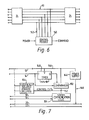
- FIG. 6 shows the connection between a control module 140 and the six wire cable embodiment 10 at a location between two monitoring modules 24.
- the control module 140 may be physically spaced away from the six wire embodiment 10 by means of an extension cable 142 and located in a convenient place, close to auxiliary power and equipment controls.
- Auxiliary power is preferred for the control module because it may require more power for its operation than is conveniently available from the embodiment 10.
- FIG. 7 is a diagram of control module 140. Cable power, available between wires 12 and 20 is not utilized. Instead, a separate power supply 144, isolated from the local power source, is employed and referenced to the complete system by connecting common wire 20 to the negative output. Positive power supply voltage is then available on wire 146.
- timer 148 activates on the positive transition of data wire 14 towards a logic high.
- Timer 148 provides a logic high to comparator 150 for the duration of a characteristic time To determined by the RC network connected to timer 148.
- Comparator 150 activates control wire 152 when data wire 14 has remained in the logic high condition for a time T greater than T.
- control wire 152 causes a relay closure which activates or deactivates equipment or machinery. This is accomplished by means of electrically isolated control circuitry 154 to insure that local power transients or ground loops are not coupled into the electrical system of the instant invention. More sophisticated control is possible by providing a control signal which is dependent on the length of time that data wire 14 remains in the logic high state, dependent on the voltage on wire 12, etc.
- Status communication logic 156 places an output on measurement wire 18 which is superimposed on the output already on the measurement wire due to the transducer at monitoring module 24 on the master electronics side of the connection of the control module 140 to apparatus 10. This additional output measured by the master electronics 8 confirms that the control activation signal did indeed occur. More sophisticated means of status monitoring are possible. Rather than just indicating that a control signal has been issued, the status of the controlled equipment or machinery could be monitored by use of a supplemental transducer which measures the controlled function and electronics which converts the transducer output to an output signal of suitable form which is superimposed on the existing output on the measurement wire.
- control apparatus There are many other alternatives to the control apparatus described above. One would be to add another control wire to the cable which is connected to all control modules. Any control module is then activated when the data wire and the control wire are logic high simultaneously. Since the data wire is logic high only at one location at a time and that location is known, any desired control modules can be activated during a normal cable read-out sequence.
Landscapes
- Engineering & Computer Science (AREA)
- Computer Networks & Wireless Communication (AREA)
- Signal Processing (AREA)
- Arrangements For Transmission Of Measured Signals (AREA)
Applications Claiming Priority (2)
| Application Number | Priority Date | Filing Date | Title |
|---|---|---|---|
| US303327 | 1981-09-18 | ||
| US06/303,327 US4413259A (en) | 1981-09-18 | 1981-09-18 | Cascade monitoring apparatus |
Publications (1)
| Publication Number | Publication Date |
|---|---|
| EP0076586A1 true EP0076586A1 (de) | 1983-04-13 |
Family
ID=23171558
Family Applications (1)
| Application Number | Title | Priority Date | Filing Date |
|---|---|---|---|
| EP82304906A Withdrawn EP0076586A1 (de) | 1981-09-18 | 1982-09-17 | In Kaskade geschaltete Überwachungseinrichtung |
Country Status (5)
| Country | Link |
|---|---|
| US (1) | US4413259A (de) |
| EP (1) | EP0076586A1 (de) |
| JP (1) | JPS5862795A (de) |
| CA (1) | CA1184267A (de) |
| GB (1) | GB2106291A (de) |
Cited By (1)
| Publication number | Priority date | Publication date | Assignee | Title |
|---|---|---|---|---|
| EP0088067A1 (de) * | 1982-02-25 | 1983-09-07 | CIFCO Société Anonyme | Verfahren zur Fernmessung, Fernmeldung und Fernsteuerung, insbesondere anwendbar auf die Erkennung von Feuer und unbefugtem Eindringen, sowie auf Beleuchtungsanlagen |
Families Citing this family (18)
| Publication number | Priority date | Publication date | Assignee | Title |
|---|---|---|---|---|
| NO149868C (no) * | 1981-04-15 | 1984-07-04 | Bjoern R Hope | Anordning for distribusjon og/eller ekstraksjon av signaler |
| CH664637A5 (de) * | 1982-04-28 | 1988-03-15 | Cerberus Ag | Verfahren zur uebertragung von messwerten in einem ueberwachungssystem. |
| US4546649A (en) * | 1982-09-27 | 1985-10-15 | Kantor Frederick W | Instrumentation and control system and method for fluid transport and processing |
| JPS6073799A (ja) * | 1983-09-29 | 1985-04-25 | 工業技術院長 | 自律的信号伝送方式による多数検出器の接続方法 |
| US4603318A (en) * | 1983-11-14 | 1986-07-29 | Philp Robert J | Telemetry and like signaling systems |
| US4617566A (en) * | 1983-12-15 | 1986-10-14 | Teleplex Corporation | Addressable-port, daisy chain telemetry system with self-test capability |
| US4723120A (en) * | 1986-01-14 | 1988-02-02 | International Business Machines Corporation | Method and apparatus for constructing and operating multipoint communication networks utilizing point-to point hardware and interfaces |
| USRE33807E (en) * | 1987-02-09 | 1992-01-28 | Sentrol, Inc. | Self-powered sensor for use in closed-loop security system |
| US4745398A (en) * | 1987-02-09 | 1988-05-17 | Sentrol, Inc. | Self-powered sensor for use in closed-loop security system |
| GB8804340D0 (en) * | 1988-02-24 | 1988-03-23 | Marconi Electronic Devices | Signalling systems |
| US5292127C1 (en) | 1992-10-02 | 2001-05-22 | Arcade Planet Inc | Arcade game |
| US5418934A (en) * | 1993-09-30 | 1995-05-23 | Intel Corporation | Synchronizing chained distributed digital chronometers by the use of an echo signal |
| JP3465263B2 (ja) * | 1996-09-04 | 2003-11-10 | オムロン株式会社 | 動作統括制御装置 |
| JPH11353986A (ja) * | 1998-06-09 | 1999-12-24 | Keyence Corp | 複数エリアセンサ用制御器 |
| US6212457B1 (en) | 1999-08-05 | 2001-04-03 | Trw Inc. | Mixed parallel and daisy chain bus architecture in a vehicle safety system |
| DE102008057474B4 (de) * | 2008-11-14 | 2012-08-02 | Kg Transmitter Components Gmbh | Meßumformer |
| WO2011012146A1 (en) * | 2009-07-30 | 2011-02-03 | Prysmian S.P.A. | Method and system for monitoring a cable system of an electric power transmission system |
| CA2769228C (en) | 2009-07-30 | 2017-02-14 | Prysmian S.P.A. | Apparatus and method for generating electric energy in an electric power transmission system |
Citations (4)
| Publication number | Priority date | Publication date | Assignee | Title |
|---|---|---|---|---|
| NL7201886A (de) * | 1971-02-12 | 1972-08-15 | ||
| FR2214385A5 (de) * | 1973-01-16 | 1974-08-09 | Honeywell Bull Soc Ind | |
| FR2436401A1 (fr) * | 1978-09-13 | 1980-04-11 | Bendix Corp | Systeme de multiplexage a ligne unique pour dispositifs de detection et d'actionnement |
| EP0035277A1 (de) * | 1980-03-05 | 1981-09-09 | Georg Prof. Dr. Färber | Sequentielles Übertragungssystem zum adressenlosen Anschliessen mehrerer Teilnehmer an eine Zentrale |
Family Cites Families (5)
| Publication number | Priority date | Publication date | Assignee | Title |
|---|---|---|---|---|
| US3403379A (en) * | 1965-05-27 | 1968-09-24 | Eg & G Int | Measurement apparatus employing long-line call-up system |
| US3988730A (en) * | 1974-12-31 | 1976-10-26 | Motorola, Inc. | Multiple parameter monitoring and readout system with sampling of parameters of higher priority than the highest parameter which is out of tolerance |
| US4114138A (en) * | 1976-08-23 | 1978-09-12 | Bell Telephone Laboratories, Incorporated | Selective calling circuit |
| US4290055A (en) * | 1979-12-05 | 1981-09-15 | Technical Development Ltd | Scanning control system |
| JPS56127294A (en) * | 1980-03-12 | 1981-10-05 | Tarou Ueda | Method of measuring multipoint electric characteristic values |
-
1981
- 1981-09-18 US US06/303,327 patent/US4413259A/en not_active Expired - Lifetime
-
1982
- 1982-09-17 GB GB08226484A patent/GB2106291A/en not_active Withdrawn
- 1982-09-17 CA CA000411697A patent/CA1184267A/en not_active Expired
- 1982-09-17 EP EP82304906A patent/EP0076586A1/de not_active Withdrawn
- 1982-09-18 JP JP57163058A patent/JPS5862795A/ja active Pending
Patent Citations (4)
| Publication number | Priority date | Publication date | Assignee | Title |
|---|---|---|---|---|
| NL7201886A (de) * | 1971-02-12 | 1972-08-15 | ||
| FR2214385A5 (de) * | 1973-01-16 | 1974-08-09 | Honeywell Bull Soc Ind | |
| FR2436401A1 (fr) * | 1978-09-13 | 1980-04-11 | Bendix Corp | Systeme de multiplexage a ligne unique pour dispositifs de detection et d'actionnement |
| EP0035277A1 (de) * | 1980-03-05 | 1981-09-09 | Georg Prof. Dr. Färber | Sequentielles Übertragungssystem zum adressenlosen Anschliessen mehrerer Teilnehmer an eine Zentrale |
Cited By (1)
| Publication number | Priority date | Publication date | Assignee | Title |
|---|---|---|---|---|
| EP0088067A1 (de) * | 1982-02-25 | 1983-09-07 | CIFCO Société Anonyme | Verfahren zur Fernmessung, Fernmeldung und Fernsteuerung, insbesondere anwendbar auf die Erkennung von Feuer und unbefugtem Eindringen, sowie auf Beleuchtungsanlagen |
Also Published As
| Publication number | Publication date |
|---|---|
| JPS5862795A (ja) | 1983-04-14 |
| US4413259A (en) | 1983-11-01 |
| CA1184267A (en) | 1985-03-19 |
| GB2106291A (en) | 1983-04-07 |
Similar Documents
| Publication | Publication Date | Title |
|---|---|---|
| EP0076586A1 (de) | In Kaskade geschaltete Überwachungseinrichtung | |
| US4613848A (en) | Multiple-zone intrusion detection system | |
| EP0254142B1 (de) | Ein- oder Mehrfachtransduktor zum Messen einer oder mehrerer physikalischen oder elektrischen Grössen | |
| EP0806751B1 (de) | Automatische Adressierung in einer Gefahrenmeldeanlage | |
| JPH03501557A (ja) | アドレス処理機構 | |
| GB2211329A (en) | Event detection system | |
| US4628315A (en) | Addressable transducer with improved address signal processing | |
| US5007042A (en) | Method and apparatus for transmitting analog data embedded in a digital pulse train | |
| EP0023105A1 (de) | System und Verfahren zur Verarbeitung von Multiplexinformation | |
| US5168273A (en) | Sequential analog/digital data multiplexing system and method | |
| JPS58181200A (ja) | 汎用入出力装置 | |
| ATE23759T1 (de) | Gleichstrommeldeanlage. | |
| CN201057569Y (zh) | 基于总线技术的数字量线型感温火灾探测器 | |
| US4872007A (en) | Transducer for measuring pressure in gas-filled cables | |
| WO1989007874A1 (en) | Addressable transducer with improved response signal processing | |
| BR8303565A (pt) | Procesos e instalacao para o rastreamento automatico do valor de medida do alarme e da identificacao do alarme em uma instalacao de alarme | |
| US3796993A (en) | Analog input device for data transmission systems | |
| GB2173330A (en) | Monitoring system | |
| US4746911A (en) | Alarm device for isolated pipe systems | |
| EP0330448A1 (de) | Meldesysteme | |
| DE3362119D1 (en) | Method and device for automatically demanding signal measure values and signal identification in an alarm installation | |
| GB2173618A (en) | Alarm monitoring installation | |
| JPS5821039Y2 (ja) | 2 センシキデンソウキ | |
| EP0087307A2 (de) | Temperaturüberwachungssysteme | |
| RU2115098C1 (ru) | Способ измерения среднего значения параметра, в частности температуры, неоднородной среды |
Legal Events
| Date | Code | Title | Description |
|---|---|---|---|
| PUAI | Public reference made under article 153(3) epc to a published international application that has entered the european phase |
Free format text: ORIGINAL CODE: 0009012 |
|
| 17P | Request for examination filed |
Effective date: 19821007 |
|
| AK | Designated contracting states |
Designated state(s): AT BE CH DE FR IT LI NL SE |
|
| STAA | Information on the status of an ep patent application or granted ep patent |
Free format text: STATUS: THE APPLICATION IS DEEMED TO BE WITHDRAWN |
|
| 18D | Application deemed to be withdrawn |
Effective date: 19841023 |
|
| RIN1 | Information on inventor provided before grant (corrected) |
Inventor name: LUTZ, MICHAEL ALAN Inventor name: KROYMANN, HOWARD BRETT Inventor name: SOFTKY, EDWARD HARVEY Inventor name: TAYEB, ABDUL MOHAMED |