EP0087357A2 - Schneller Rechenkreis einer diskreten Fouriertransformation eines Signals, insbesondere für ein Foucaultstrom-Kontrollgerät - Google Patents
Schneller Rechenkreis einer diskreten Fouriertransformation eines Signals, insbesondere für ein Foucaultstrom-Kontrollgerät Download PDFInfo
- Publication number
- EP0087357A2 EP0087357A2 EP83400308A EP83400308A EP0087357A2 EP 0087357 A2 EP0087357 A2 EP 0087357A2 EP 83400308 A EP83400308 A EP 83400308A EP 83400308 A EP83400308 A EP 83400308A EP 0087357 A2 EP0087357 A2 EP 0087357A2
- Authority
- EP
- European Patent Office
- Prior art keywords
- memory
- output
- circuit
- coefficients
- samples
- Prior art date
- Legal status (The legal status is an assumption and is not a legal conclusion. Google has not performed a legal analysis and makes no representation as to the accuracy of the status listed.)
- Ceased
Links
Images


Classifications
-
- G—PHYSICS
- G01—MEASURING; TESTING
- G01N—INVESTIGATING OR ANALYSING MATERIALS BY DETERMINING THEIR CHEMICAL OR PHYSICAL PROPERTIES
- G01N27/00—Investigating or analysing materials by the use of electric, electrochemical, or magnetic means
- G01N27/72—Investigating or analysing materials by the use of electric, electrochemical, or magnetic means by investigating magnetic variables
- G01N27/82—Investigating or analysing materials by the use of electric, electrochemical, or magnetic means by investigating magnetic variables for investigating the presence of flaws
- G01N27/90—Investigating or analysing materials by the use of electric, electrochemical, or magnetic means by investigating magnetic variables for investigating the presence of flaws using eddy currents
- G01N27/9046—Investigating or analysing materials by the use of electric, electrochemical, or magnetic means by investigating magnetic variables for investigating the presence of flaws using eddy currents by analysing electrical signals
-
- G—PHYSICS
- G06—COMPUTING OR CALCULATING; COUNTING
- G06F—ELECTRIC DIGITAL DATA PROCESSING
- G06F17/00—Digital computing or data processing equipment or methods, specially adapted for specific functions
- G06F17/10—Complex mathematical operations
- G06F17/14—Fourier, Walsh or analogous domain transformations, e.g. Laplace, Hilbert, Karhunen-Loeve, transforms
- G06F17/141—Discrete Fourier transforms
Definitions
- the present invention relates to a circuit for rapidly calculating the discrete Fourier transform of a signal. It finds an application in the analysis of measurement signals, in particular in the analysis of the voltage delivered by a non-destructive control probe by eddy currents.
- this type of control consists in creating a variable magnetic field using a primary winding, in subjecting a part to be controlled to this field and in taking samples at the terminals of a secondary winding disposed near the controlled part. tension and analyze it.
- the primary and secondary windings are arranged in a probe whose structure can take different forms (they can be confused, arranged in a bridge, etc.). Any defect in the controlled part (change in size, variation in electrical conductivity, variation in magnetic permeability, cracks, etc.) changes the phase and intensity of the eddy currents induced in the part and, correspondingly, changes the voltage taken from the terminals of the probe.
- the processing of the measurement signal consists of in the determination of the harmonics of this signal.
- it is a Fourier transformation.
- the amplitude of harmonic 3 which fairly well reflects the structure of the room, but which remains sensitive to the weight of the room, can be weighted by the phase or the amplitude of the fundamental term which is a function precisely the weight of the part, to obtain a result that is substantially independent of the weight.
- the first harmonic component plays a privileged role. It can be represented, in an impedance plane by a point which, in the event of the part scrolling in a so-called "differential" sensor, describes an 8-shaped curve whose amplitude and orientation make it possible to determine the defects in the part checked.
- the circuit of the in - vention is used at the output of a measuring apparatus as illustrated in Figure 1.
- a measurement apparatus any 110 provides at an output 111, a measurement signal analog.
- a signal processing circuit 120 has an input 121 which is connected to the output 111, and an output 122 which delivers information relating to the harmonics of the measurement signal.
- the present invention is preferably placed in the context of non-destructive testing by eddy currents.
- the app reil 110 includes an alternating current generator 112 followed by an amplifier circuit 113 supplying a probe 114.
- the parts to be checked 116 pass near the probe 114.
- the measurement signal taken by the probe is amplified by a circuit 118 and appears on the output 111. It is this signal which is applied to the analysis circuit 120 ..
- a circuit 124 for processing the results can complete the analysis circuit in order to act on a sorting member 125 suitable, for example , to eject the defective parts.
- the analysis circuit 120 performs a Fourier transformation of the signal applied to it.
- analog type analysis circuits are possible, today it is preferred to work in digital, which allows better precision and greater flexibility of analysis.
- the signals to be processed are therefore first converted into digital samples and then undergo the transformation in question. As this operation is no longer carried out on a continuous quantity, but on sequences of samples, it is traditionally called “discrete” Fourier transformation, or abbreviated as TFD (in English terminology DFT for "Discrete Fourier Transform”).
- the object of the present invention is to further accelerate the calculation of harmonics.
- the invention renounces the rapid Fourier transformation which has just been mentioned to retain the elementary process mentioned above and which is deemed inappropriate.
- the invention therefore goes against current prejudices in the field which always recommend the search for fast algorithms with passage through intermediate states.
- the invention results from a fine analysis carried out by the inventors on the specific nature of the discrete Fourier transformation in the case of non-destructive testing by eddy currents.
- the particularity of this technique is that it requires, in fact, only the first harmonics of the signal and not all of the N harmonics that the usual fast Fourier transformation gives. The question that arises is therefore to know how many operations require the rapid Fourier transformation when the development is limited to the first harmonics.
- the first inventive idea on which the present invention is based is therefore to actually work on the following expressions: that is to say to actually perform products of samples x (n) by coefficients and and make sums on the products obtained.
- the invention recommends another solution which is the use of a particular wired circuit, essentially constituted by a multiplier followed by an accumulator.
- the advantage of such a solution is to be able to use circuits operating in wired logic, which are much faster than program circuits.
- the calculation time of these circuits can be of the order of a hundred nanoseconds.
- An additional advantage of the invention is to be able to use certain circuits which are found today in the trade and which are capable of carrying out simultaneously multiplications, additions and an accumulation, in a very short time.
- the sine and cosine coefficients necessary for the calculations could be generated by program.
- the invention also prefers to use a circuit, in this case a memory, where all the useful coefficients are stored.
- This memory is of the programmable read only memory type (abbreviated as PROM for "Programmable Read Only Memory”). It is divided into as many blocks as there are harmonic components to be calculated, the block of rank k containing the coefficients of index k necessary for the calculation of the k th harmonic.
- the addressing of the two memories where the samples and the coefficients are stored could be done by instructions from a control microprocessor. This solution would require approximately 100 ⁇ s of preparation and would ruin the advantage of using a multiplier working in 100 ns. According to the invention, on the contrary, the reading of the two memories is carried out using the same counter which very quickly delivers the successive addresses of the samples and of the coefficients.
- the entire structure of the computer of the invention is determined by the desire to obtain a high speed of calculation and this despite the apparent slowness of the calculation process chosen.
- the invention can be applied whenever it is desired to rapidly calculate the first harmonic components of a measurement signal. It is however in the case of non-destructive testing by eddy currents that it finds a privileged application, as explained above and this is the reason why the description which follows will be based on this example.
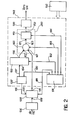
- FIG. 2 The general diagram of the circuit of the invention is illustrated in FIG. 2 where we recognize elements already represented in the previous figure, namely the analog-digital converter 126, and the acquisition memory 118.
- FIG. 2 more specifically illustrates the structure of the assembly 140 which makes it possible to calculate the real and imaginary parts of the first harmonics, from the N samples stored in the acquisition memory 128.
- this assembly 140 essentially comprises a read-only memory 152, a counter 132, a multiplier 160, an accumulator 170 and a sequencer 178. These various elements will be described in detail.
- the read-only memory 152 is of the PROM type. It has an address input 154 and a data output 156. This memory is divided into as many blocks as there are harmonics to be calculated (in the example taken in three blocks).
- the k th block contains the coefficients and where N is the number of samples contained in the acquisition memory 128 and where n takes all the values going from 0 to Nl. In the first block, we therefore find the coefficients and in the second the coefficients and and in the third the coefficients and
- the counter 132 has two outputs each carrying a set of addresses: the first output 136 is connected to an address input 130 of the acquisition memory 128 and the second, 137, to the address input 154 of the coefficient memory 152.
- the addresses delivered by the counter 132 respectively determine a sample in the acquisition memory 128 and a coefficient in one of the blocks of the coefficient memory 132.
- To select a block among three, 2 more addressing bits are required and to select either the sine series or the cosine series, 1 more addressing bit is required, i.e. 9 + 2 + 1 12 bits for addressing memory 152.
- the multiplier circuit 160 has two inputs, 161 and 162, the first connected to the output 131 of the acquisition memory 128, the second to the output 156 of the coefficient memory 152.
- the multiplier also has an output 163.
- the accumulator circuit 170 has an input 171 which is connected to the output 163 of the multi folder 160 and an output 172 which conveys the real and imaginary parts of the harmonics sought.
- the sequencer circuit 178 is connected by a connection 180 to the counter, by a connection 181 to the acquisition memory 128, by a connection 182 to the coefficient memory 152, by a connection 183 to the multiplier 1.60 and by a connection 184 to the 'accumulator 170.
- the assembly shown also comprises a microprocessor 150 which is connected to all the elements mentioned above (by connections not shown in FIG. 3 for simplification, but which will appear in the following figures).
- the sequencer circuit 178 addresses counting pulses to the counter 132 by the connection 180. By the connection 181, it controls the reading in the acquisition memory 128, and simultaneously, the reading of the coefficients in the memory 152.
- Reading of the samples and coefficients in their respective memories is obtained by means of the counter 132, the content of which changes from 0 to 511 under the control of the pulses which it receives from the sequencer.
- the sequencer first controls the reading of the cosine samples. At each pulse a sample and a cosine coefficient appear simultaneously on the inputs 161 and 162 of the multiplier. The sequencer then commands, by connection 183, to the multiplier 160 to carry out the product of the two data. Then, by connection 184, the sequencer controls the accumulator 170, which takes into account the partial product delivered by the multiplier.
- the sequencer signals to the microprocessor 150 that a complete calculation has just been carried out and that there is at the output 172 of the accumulator 170 the real part of the first harmonic.
- the microprocessor 150 then reads the result and orders the sequencer to carry out the following sequence making it possible to obtain the imaginary part.
- the sequencer selects, by an appropriate signal conveyed by the connection 182, the series of sine coefficients, always in the first block of the memory of coefficients. After 512 new read-multiply and accumulate operations, the accumulator delivers the imaginary part of the first harmonic. The microprocessor 150 reads this result and orders the sequencer to proceed to the calculation phase of the second harmonic.
- the invention recommends the use of an auxiliary microprocessor referenced 190 in FIG. 2 and which, taking into account the particular task, which can be wired and can be therefore, very fast. It is a so-called "mathematical" microprocessor capable of carrying out the operations of squaring (to obtain R 2 and I 2 ), of addition (to obtain R 2 + I 2 ), of root extraction square (to obtain the modulus of the harmonic), calculating a quotient (of I by R) and calculating the arctangent of the quotient obtained (to obtain the argument of the harmonic considered).
- multiplier circuit 160 and the accumulator 170 on a single integrated circuit symbolically represented by the block 200.
- Such circuits exist commercially. It may be, for example, the TDC 1010J circuit marketed by the American company TRW.
- One of the advantages of the invention is precisely to allow the use of such high performance circuits, in particular with regard to the speed of calculation.
- the central microprocessor 150 is linked to the acquisition memory 128, the coefficient memory 152, the multiplier 160 and the accumulator 170, so that it is possible to use these components for other tasks than those required by the harmonic analysis described above. These connections appear better in FIG. 3 where groups of connections or buses are represented, with the necessary interface circuits.
- This figure shows: an interface circuit 210 allowing the microprocessor to write and read in the acquisition memory 128, an interface circuit 212 allowing the microprocessor to read the calculation results in circuit 200, another interface circuit 213 giving access to the coefficient memory 152, an interface circuit 214 which gives access to the counter 132, a locking circuit 216 ("latch" circuit in angosaxon, which is transparent vis-à-vis the signal applied to it or which stores the latter), bidirectional buffer circuits 218 and 220 arranged at the output of the memory 128 and at the input of the circuit 200, a unidirectional buffer circuit 222 disposed on the data bus coming from the converter 126 and allowing the writing data into memory 128, a unidirectional buffer circuit 224 disposed on the bus and giving the microprocessor access to the calculation circuit 200, finally, an interface circuit 226 allowing the introduction by the control and data microprocessor in circuit 200.
- the advantage of allowing the microprocessor to be able to read from the memories is that it becomes possible to choose from them a set of coefficients or samples from among several.
- the microprocessor determines which game is best suited to the problem to be solved.
- access to the counter 132 makes it possible to load the latter to a selected initial content.
- FIGS. 4 to 6 illustrate more specifically specific embodiments of the circuit of the invention in the following specific case: the calculations are carried out with 512 samples; the multiplication-accumulation circuit 200 operates with numbers of 16 binary elements (or bits); the result is given with 35 bits; the acquisition memory works with 12-bit words and the coefficient memory with 15-bit words (we could strictly use 16-bit words since circuit 200 accepts them, but there would be risks of overflow in the accumulator).
- the locking circuit (latch") 216 (constituted for example by a circuit 74 LS 373 for the last eight connections IA4 to IAll and a circuit 74 LS 75 for the connection IA3).
- the 9 addressing outputs intended for the acquisition memory are referenced B0, Bl, ... B8.
- the coefficient memory 152 can be composed of two memory circuits (for example of the type 2732) each addressed by the 12 connections IAO to IA11.
- the 12 address bits are divided into two bits defining one of the three coefficient blocks, 1 bit defining the cosine or sine sequence in the chosen block, and 9 bits defining a coefficient from 512 in the chosen sequence.
- the output connections are referenced PO to P15.
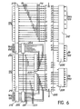
- FIG. 5 represents the environment of the acquisition memory 12'8 in an embodiment which uses three storage circuits (for example of the type 2114) with 4 outputs each.
- This memory is addressed by the 9 inputs B0, Bl, ..., B8.
- the 3x4 12 inputs-outputs are connected to a buffer circuit 218 formed of bidirectional circuits (a type 8286 with 4 inputs-outputs and one of the type 81LS95 with 8 inputs-outputs).
- the output of the samples read is carried out by the 12 outputs IDO, IDl, ..., IDll.
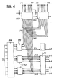
- FIG. 6 represents the calculation circuit 200 and its inputs-outputs.
- This circuit which is the centerpiece of the assembly, is for example constituted by the TDC 1010J circuit from TRW.
- This circuit includes 64 accesses referenced from 1 to 64. Accesses 1 to 7 and 56 to 64 operate either as inputs, in which case they receive the coefficients by the connections PO, ..., P15, or as outputs, in which case they deliver the most significant bits of the result to the interface circuit 213 connected to the microprocessor. Access 8 to 15 and 17 to 24 also work as inputs or outputs. As inputs they receive the samples, via the IDO, ..., ID11 connections through the buffer circuit 220 (which can be made up of two types 81 LS 95 circuits). As output they deliver the least significant bits of the result through buffer 224 then through interface 212 to the microprocessor. The other accesses (right side) allow the microprocessor to access the components. sants of circuit 200. All interface circuits can be of type 8255.
- the sequencer is not shown because it is a known circuit. It includes a high stability oscillator (quartz) followed by dividers which generate pulses at various frequencies.
- the oscillator can be a 74 LS 124 circuit and the dividers of the 74 LS 123 circuits.
- the analog-digital converter As for the analog-digital converter, it also works with 512 samples per period, on 12 bits. For a working frequency between 3 and 3000 Hz, this conversion can cause problems at the top of the range, since it is then necessary to convert 3000x512 samples per second. It is possible to resolve this difficulty by taking the samples no longer over a single period, but over several, which is possible since the signal is periodic.
- the number of periods used for conversion can be programmed and determined by the microprocessor.
Landscapes
- Physics & Mathematics (AREA)
- General Physics & Mathematics (AREA)
- Mathematical Physics (AREA)
- Engineering & Computer Science (AREA)
- Theoretical Computer Science (AREA)
- Data Mining & Analysis (AREA)
- Pure & Applied Mathematics (AREA)
- Chemical & Material Sciences (AREA)
- Mathematical Optimization (AREA)
- Mathematical Analysis (AREA)
- Computational Mathematics (AREA)
- Analytical Chemistry (AREA)
- Health & Medical Sciences (AREA)
- Pathology (AREA)
- Immunology (AREA)
- General Health & Medical Sciences (AREA)
- Biochemistry (AREA)
- Life Sciences & Earth Sciences (AREA)
- Discrete Mathematics (AREA)
- Algebra (AREA)
- Electrochemistry (AREA)
- Databases & Information Systems (AREA)
- Software Systems (AREA)
- General Engineering & Computer Science (AREA)
- Chemical Kinetics & Catalysis (AREA)
- Complex Calculations (AREA)
- Investigating Or Analyzing Materials By The Use Of Magnetic Means (AREA)
Applications Claiming Priority (2)
| Application Number | Priority Date | Filing Date | Title |
|---|---|---|---|
| BE0/207387A BE892241A (fr) | 1982-02-23 | 1982-02-23 | Circuit de calcul rapide de la transformee de fourier discrete d'un signal, destine notamment a un appareil de controle par courants de foucault. |
| BE892241 | 1982-02-23 |
Publications (2)
| Publication Number | Publication Date |
|---|---|
| EP0087357A2 true EP0087357A2 (de) | 1983-08-31 |
| EP0087357A3 EP0087357A3 (de) | 1985-08-28 |
Family
ID=3843501
Family Applications (1)
| Application Number | Title | Priority Date | Filing Date |
|---|---|---|---|
| EP83400308A Ceased EP0087357A3 (de) | 1982-02-23 | 1983-02-14 | Schneller Rechenkreis einer diskreten Fouriertransformation eines Signals, insbesondere für ein Foucaultstrom-Kontrollgerät |
Country Status (8)
| Country | Link |
|---|---|
| US (1) | US4630229A (de) |
| EP (1) | EP0087357A3 (de) |
| JP (1) | JPS58158768A (de) |
| BE (1) | BE892241A (de) |
| CA (1) | CA1199118A (de) |
| FR (1) | FR2522157B1 (de) |
| IE (1) | IE830317L (de) |
| TR (1) | TR21801A (de) |
Cited By (2)
| Publication number | Priority date | Publication date | Assignee | Title |
|---|---|---|---|---|
| CN105973272A (zh) * | 2016-07-28 | 2016-09-28 | 深圳市康必达控制技术有限公司 | 一种提高电能计量精度的方法 |
| RU2647701C1 (ru) * | 2017-03-07 | 2018-03-16 | Акционерное общество "Уральское проектно-конструкторское бюро "Деталь" | Устройство дискретного преобразования Фурье |
Families Citing this family (39)
| Publication number | Priority date | Publication date | Assignee | Title |
|---|---|---|---|---|
| US4965761A (en) * | 1988-06-03 | 1990-10-23 | General Dynamics Corporation, Pomona Div. | Fast discrete fourier transform apparatus and method |
| US5091875A (en) * | 1990-03-23 | 1992-02-25 | Texas Instruments Incorporated | Fast fourier transform (FFT) addressing apparatus and method |
| US5144565A (en) * | 1990-03-26 | 1992-09-01 | K. J. Law Engineers, Inc. | Measurement of metallurgical properties in ferromagnetic test parts |
| JPH0431965A (ja) * | 1990-05-28 | 1992-02-04 | Nec Corp | 数値演算装置 |
| US5375250A (en) * | 1992-07-13 | 1994-12-20 | Van Den Heuvel; Raymond C. | Method of intelligent computing and neural-like processing of time and space functions |
| US6563589B1 (en) | 1996-04-19 | 2003-05-13 | Kvh Industries, Inc. | Reduced minimum configuration fiber optic current sensor |
| US6891622B2 (en) | 1999-02-11 | 2005-05-10 | Kvh Industries, Inc. | Current sensor |
| US6539134B1 (en) | 1999-02-11 | 2003-03-25 | Kvh Industries, Inc. | Polarization transformer |
| US7209844B2 (en) * | 2003-09-19 | 2007-04-24 | Automotive Systems Laboratory, Inc. | Magnetic crash sensor |
| US7388370B2 (en) * | 2005-07-29 | 2008-06-17 | Automotive Systems Laboratory Systems, Inc. | Magnetic crash sensor |
| US20070188168A1 (en) * | 1999-08-26 | 2007-08-16 | Stanley James G | Magnetic sensor |
| US20080109177A1 (en) * | 2003-09-19 | 2008-05-08 | Cech Leonard S | Magnetic crash sensor |
| US7514917B2 (en) * | 2003-09-19 | 2009-04-07 | Automotive Systems Laboratory, Inc. | Magnetic crash sensor |
| US8180585B2 (en) * | 1999-08-26 | 2012-05-15 | Tk Holdings, Inc. | Magnetic crash sensor |
| US7212895B2 (en) * | 2003-12-21 | 2007-05-01 | Automotive Systems Laboratory, Inc. | Magnetic sensor |
| EP1250695A4 (de) | 1999-12-20 | 2003-07-23 | Henry Moncrieff O'connor | Verfahren zur herstellung und anzeige von komplexen daten mittels farbkodesignalen |
| US6370289B1 (en) | 2000-01-12 | 2002-04-09 | Kvh Industries, Inc. | Apparatus and method for electronic RIN reduction in fiber-optic sensors |
| US6703821B2 (en) | 2000-02-28 | 2004-03-09 | Kvh Industries, Inc. | Faraday-effect current sensor with improved vibration response |
| US6429939B1 (en) * | 2000-07-13 | 2002-08-06 | Kvh Industries, Inc. | DSP signal processing for open loop fiber optic sensors |
| US6594020B2 (en) | 2000-07-13 | 2003-07-15 | Kvh Industries, Inc | Method for controlling fiber optic sensor scale factor using amplitude modulation |
| WO2002010813A2 (en) * | 2000-08-02 | 2002-02-07 | Kvh Industries, Inc. | Reduction of linear birefringence in circular-core single-mode fiber |
| US6707558B2 (en) | 2000-08-02 | 2004-03-16 | Kvh Industries, Inc. | Decreasing the effects of linear birefringence in a fiber-optic sensor by use of Berry's topological phase |
| GB0027556D0 (en) * | 2000-11-10 | 2000-12-27 | Secretary Trade Ind Brit | Testing of electrical apparatus |
| US6836334B2 (en) * | 2001-10-31 | 2004-12-28 | Kvh Industries, Inc. | Angle random walk (ARW) noise reduction in fiber optic sensors using an optical amplifier |
| US6763153B2 (en) * | 2002-04-17 | 2004-07-13 | Kvh Industries, Inc. | Apparatus and method for electronic RIN reduction in fiber-optic sensors utilizing filter with group delay |
| US7839143B2 (en) * | 2003-09-19 | 2010-11-23 | Tk Holdings Inc. | Eddy current magnetic crash sensor |
| US7839142B2 (en) * | 2003-09-19 | 2010-11-23 | Tk Holdings, Inc. | Magnetic crash sensor |
| US7664612B2 (en) * | 2003-09-19 | 2010-02-16 | T K Holdings, Inc. | Signal processing system and method |
| US7570068B2 (en) * | 2003-09-19 | 2009-08-04 | Tk Holdings, Inc. | Signal processing system and method |
| US7772839B2 (en) | 2003-09-19 | 2010-08-10 | Tk Holdings, Inc. | Eddy current magnetic crash sensor |
| US7463987B2 (en) * | 2003-09-19 | 2008-12-09 | Takata Holdings, Inc. | Magnetic sensing system and method |
| EP1663732A2 (de) * | 2003-09-19 | 2006-06-07 | Automotive Systems Laboratory Inc. | Verfahren zur magnetischen aufprallerfassung |
| US7564249B2 (en) * | 2003-12-21 | 2009-07-21 | Tk Holdings, Inc. | Signal processing system and method |
| US11710489B2 (en) | 2004-06-14 | 2023-07-25 | Wanda Papadimitriou | Autonomous material evaluation system and method |
| US11680867B2 (en) | 2004-06-14 | 2023-06-20 | Wanda Papadimitriou | Stress engineering assessment of risers and riser strings |
| US7312607B2 (en) * | 2004-07-20 | 2007-12-25 | General Inspection Llc | Eddy current part inspection system |
| US7508190B2 (en) * | 2004-10-20 | 2009-03-24 | Electro Industries/Gauge Tech. | Test pulses for enabling revenue testable panel meters |
| US7633635B2 (en) * | 2006-08-07 | 2009-12-15 | GII Acquisitions, LLC | Method and system for automatically identifying non-labeled, manufactured parts |
| GB2457496B (en) * | 2008-02-15 | 2010-10-20 | Ge Inspection Technologies Ltd | A method and apparatus for phase sensitive detection of eddy current measurements |
Family Cites Families (15)
| Publication number | Priority date | Publication date | Assignee | Title |
|---|---|---|---|---|
| US3636333A (en) * | 1970-01-28 | 1972-01-18 | Us Navy | Fourier coefficient generator |
| US3617719A (en) * | 1970-03-11 | 1971-11-02 | Us Air Force | Staggered processing in digital or hybrid signal processors |
| US3754128A (en) * | 1971-08-31 | 1973-08-21 | M Corinthios | High speed signal processor for vector transformation |
| US3903401A (en) * | 1974-06-27 | 1975-09-02 | Bell Telephone Labor Inc | Spectrum analyzer using delta modulation encoding |
| US4084251A (en) * | 1976-03-10 | 1978-04-11 | Harris Corporation | Fourier transform generator for bi-level samples |
| US4084136A (en) * | 1976-10-21 | 1978-04-11 | Battelle Memorial Institute | Eddy current nondestructive testing device for measuring variable characteristics of a sample utilizing Walsh functions |
| US4117541A (en) * | 1977-11-07 | 1978-09-26 | Communications Satellite Corporation | Configurable parallel arithmetic structure for recursive digital filtering |
| US4138730A (en) * | 1977-11-07 | 1979-02-06 | Communications Satellite Corporation | High speed FFT processor |
| US4199660A (en) * | 1977-11-07 | 1980-04-22 | Communications Satellite Corporation | FDM/TDM Transmultiplexer |
| US4266279A (en) * | 1979-03-29 | 1981-05-05 | Motorola, Inc. | Memory system for a Doppler radar incorporating a fast Fourier transform computer |
| US4334273A (en) * | 1979-04-24 | 1982-06-08 | Kokusai Denshin Denwa Co., Ltd. | Signal processing system using a digital technique |
| FR2461304A1 (fr) * | 1979-07-12 | 1981-01-30 | Ibm France | Appareil de calcul de transformee de fourier discrete bidimensionnelle |
| US4298985A (en) * | 1979-12-31 | 1981-11-03 | The United States Of America As Represented By The Secretary Of The Army | Digital filter bank detector |
| US4467281A (en) * | 1980-02-29 | 1984-08-21 | Electric Power Research Institute, Inc. | Multi frequency eddy current test apparatus with intermediate frequency processing |
| NL8200051A (nl) * | 1982-01-08 | 1983-08-01 | Philips Nv | Inrichting en werkwijze voor het detecteren van multifrequentie tooncodesignalen. |
-
1982
- 1982-02-23 BE BE0/207387A patent/BE892241A/fr not_active IP Right Cessation
- 1982-05-10 FR FR8208071A patent/FR2522157B1/fr not_active Expired
-
1983
- 1983-02-14 EP EP83400308A patent/EP0087357A3/de not_active Ceased
- 1983-02-16 IE IE830317A patent/IE830317L/xx unknown
- 1983-02-18 US US06/467,761 patent/US4630229A/en not_active Expired - Fee Related
- 1983-02-21 CA CA000421990A patent/CA1199118A/en not_active Expired
- 1983-02-22 TR TR21801A patent/TR21801A/xx unknown
- 1983-02-23 JP JP58027864A patent/JPS58158768A/ja active Pending
Cited By (3)
| Publication number | Priority date | Publication date | Assignee | Title |
|---|---|---|---|---|
| CN105973272A (zh) * | 2016-07-28 | 2016-09-28 | 深圳市康必达控制技术有限公司 | 一种提高电能计量精度的方法 |
| CN105973272B (zh) * | 2016-07-28 | 2018-01-19 | 深圳市康必达控制技术有限公司 | 一种提高电能计量精度的方法 |
| RU2647701C1 (ru) * | 2017-03-07 | 2018-03-16 | Акционерное общество "Уральское проектно-конструкторское бюро "Деталь" | Устройство дискретного преобразования Фурье |
Also Published As
| Publication number | Publication date |
|---|---|
| BE892241A (fr) | 1982-06-16 |
| EP0087357A3 (de) | 1985-08-28 |
| US4630229A (en) | 1986-12-16 |
| CA1199118A (en) | 1986-01-07 |
| TR21801A (tr) | 1985-07-18 |
| FR2522157B1 (fr) | 1985-10-11 |
| FR2522157A1 (fr) | 1983-08-26 |
| IE830317L (en) | 1983-08-23 |
| JPS58158768A (ja) | 1983-09-21 |
Similar Documents
| Publication | Publication Date | Title |
|---|---|---|
| EP0087357A2 (de) | Schneller Rechenkreis einer diskreten Fouriertransformation eines Signals, insbesondere für ein Foucaultstrom-Kontrollgerät | |
| EP0642683B1 (de) | Verfahren und testanlage zur entwicklung einer integrierten schaltung. | |
| EP0198729B1 (de) | System zur Simulation einer elektronischen Schaltung | |
| CN113593594B (zh) | 语音增强模型的训练方法和设备及语音增强方法和设备 | |
| FR2568698A1 (fr) | Simulateur logique ayant une capacite de memoire aussi reduite que possible | |
| FR2705155A1 (fr) | Dispositif et méthode pour générer une fonction d'approximation. | |
| EP0546624A1 (de) | Datenverarbeitungssystem mit teilweise nicht-linearer Funktion | |
| EP0511095B1 (de) | Verfahren und Vorrichtung zur Kodierung und Dekodierung eines numerischen Signals | |
| EP0088652B1 (de) | Wirbelstrom-Prüfapparat mit elektronischen Ausgleichvorrichtungen | |
| FR2776093A1 (fr) | Circuit processeur programmable muni d'une memoire reconfigurable, pour realiser un filtre numerique | |
| EP0901637B1 (de) | Testverfahren für elektronische bauteile | |
| FR2634084A1 (fr) | Circuit integre et dispositif de traitement d'images | |
| EP0568424A1 (de) | Verfahren zur automatischen Erzeugung einer implizierten Darstellung der Primimplikanten einer Funktion | |
| EP0022513B1 (de) | Gerät zur Berechnung der zweidimensionalen diskreten Fouriertransformation | |
| EP0924627A1 (de) | Pipelineprozessor für die schnelle Fourier-Transformation | |
| EP0310485A1 (de) | Laufendes Guthaben-Registrierungsverfahren in einem elektronischen Speicher und System zur Verwirklichung dieses Verfahrens | |
| FR2641631A1 (fr) | Montage de transformation de fourier rapide en temps reel | |
| EP0034956A1 (de) | Synchronisier- und Prüfsignalgenerator und einen solchen Generator enthaltendes Fernsehsystem | |
| FR2658933A1 (fr) | Systeme de commande du deroulement de sequences de tests dans un appareil de traitement de l'information. | |
| EP0242258B1 (de) | Vorrichtung zur Durchführung eines Algorithmus (Leroux-Gueguen) zum Codieren eines Signals durch Linearvorhersage | |
| FR2551575A1 (fr) | Transformateur polyphonique de doigte pour instruments a cordes | |
| FR2459524A1 (fr) | Synthetiseur numerique polyphonique de signaux periodiques et instrument de musique comportant un tel synthetiseur | |
| EP2028622A2 (de) | Bearbeiten von Vektorgrafiken, insbesondere von geographischen Karten | |
| EP0897153A1 (de) | Verfahren zum Feststellen der Startzeit eines Informationssystems | |
| EP0190514B1 (de) | On-line-Testeinrichtung für einen Rechnerkreis der diskreten Fouriertransformation und Kreis der eine solche Einrichtung enthält |
Legal Events
| Date | Code | Title | Description |
|---|---|---|---|
| PUAI | Public reference made under article 153(3) epc to a published international application that has entered the european phase |
Free format text: ORIGINAL CODE: 0009012 |
|
| AK | Designated contracting states |
Designated state(s): AT CH DE GB IT LI LU NL SE |
|
| PUAL | Search report despatched |
Free format text: ORIGINAL CODE: 0009013 |
|
| AK | Designated contracting states |
Designated state(s): AT CH DE GB IT LI LU NL SE |
|
| 17P | Request for examination filed |
Effective date: 19860201 |
|
| 17Q | First examination report despatched |
Effective date: 19880210 |
|
| STAA | Information on the status of an ep patent application or granted ep patent |
Free format text: STATUS: THE APPLICATION HAS BEEN REFUSED |
|
| 18R | Application refused |
Effective date: 19880804 |
|
| RIN1 | Information on inventor provided before grant (corrected) |
Inventor name: D'HONDT, JEAN-PIERRE |