EP0087572A1 - Parois latérale de compartiment de charge ayant un dispositif d'accumulation de force - Google Patents
Parois latérale de compartiment de charge ayant un dispositif d'accumulation de force Download PDFInfo
- Publication number
- EP0087572A1 EP0087572A1 EP83100520A EP83100520A EP0087572A1 EP 0087572 A1 EP0087572 A1 EP 0087572A1 EP 83100520 A EP83100520 A EP 83100520A EP 83100520 A EP83100520 A EP 83100520A EP 0087572 A1 EP0087572 A1 EP 0087572A1
- Authority
- EP
- European Patent Office
- Prior art keywords
- side board
- side wall
- upper side
- board portion
- wall part
- Prior art date
- Legal status (The legal status is an assumption and is not a legal conclusion. Google has not performed a legal analysis and makes no representation as to the accuracy of the status listed.)
- Granted
Links
- 238000013459 approach Methods 0.000 abstract 1
- 238000010276 construction Methods 0.000 description 2
- 230000000694 effects Effects 0.000 description 2
- 238000009434 installation Methods 0.000 description 2
- 230000002093 peripheral effect Effects 0.000 description 1
- 238000005096 rolling process Methods 0.000 description 1
Images
Classifications
-
- B—PERFORMING OPERATIONS; TRANSPORTING
- B60—VEHICLES IN GENERAL
- B60J—WINDOWS, WINDSCREENS, NON-FIXED ROOFS, DOORS, OR SIMILAR DEVICES FOR VEHICLES; REMOVABLE EXTERNAL PROTECTIVE COVERINGS SPECIALLY ADAPTED FOR VEHICLES
- B60J5/00—Doors
- B60J5/04—Doors arranged at the vehicle sides
- B60J5/0497—Doors arranged at the vehicle sides for load transporting vehicles or public transport, e.g. lorries, trucks, buses
- B60J5/0498—Doors arranged at the vehicle sides for load transporting vehicles or public transport, e.g. lorries, trucks, buses with rigid panels pivoting about a horizontal axis
Definitions
- the invention relates to a closed structure for a truck or trailer with one or more open side walls, each consisting of a lower and an upper side wall part, of which the lower side wall part is pivotable at its lower edge about a horizontal axis and the upper side wall part at its
- the lower end is guided by a link attached to fixed structural parts and at its upper end by a horizontal guide arranged under the roof and is connected to the lower side of the side wall by a cable that engages the upper end of the upper side of the side wall so that when the lower side of the side wall is folded down a horizontal position is pulled under the roof, with a support roller being attached to both sides of the upper side wall part in the central area of the upper half thereof, against which the inner surface of the upper side wall part bears at least in the closed state, and that the pivot pins of the handlebars in the plane of the g closed side wall.
- a spring one end of which is attached to the vehicle and the other end is attached to the side surface of the upper side wall part by means of a pull rope and a pulley, so that the spring is biased in the open or closed state of the side wall parts.
- the structure according to the invention is advantageously characterized in that the cable pull acting at the upper end of the upper side wall part is guided via a deflection roller through a loose roller to a fastening point is guided on the vehicle, with the continuation of the cable extending from the loose roller via deflection rollers to the attachment point on the lower part of the side wall.
- the advantages of the construction according to the invention are that the opening or closing movement of the upper shelf wall part is supported especially in the initial phase by a spring force acting in the same direction.
- the design of the cable pull with a loose roller means that the lower side wall part exerts a greater force on the upper side wall part by means of a cheaper cable fastening. The structure can thus be operated with little effort.
- the structure according to the invention for a truck or a trailer for such consists of walls, at least one of which is designed as a tail lift.
- either both longitudinal walls or the rear wall and, in the case of a trailer, the front wall can also be designed as a tail lift.
- the known tail lift consists of a lower and an upper side wall part, the lower side wall and the lower side wall part being pivotally connected to the vehicle body at the lower edge and by pivoting the opening of the lower side wall part, the upper side wall part is acted upon by an upper edge thereof Cable pulled under the roof of the superstructure, where it occupies approximately the horizontal position.
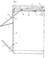
- the known upper side wall part 2 has at its upper edge a fulcrum which can be pulled inwards by means of wheels 12 in a guide rail 11 and is connected to the free end of a link 3 articulated between the upper and the lower fulcrum on the body.
- the one between the upper loading platform wall 1 and the stanchions 19 or these corresponding wall parts freely pivotable handlebar 3 has a pivot on both sides, one being inserted in a bearing which is mounted within the stanchion 19, the other engaging in a pivot bearing which engages in the double wall the upper tail lift 2 is inserted at the lower edge with a lateral opening.
- the upper side wall part 2 itself is designed so that the double wall have at their upper and lower edges a U-profile with an attached web, which forms a stop at the bottom of the lower tail lift 2 and above on a longitudinal box section.
- the ends of the cable pulls 13 are fastened to the axes, provided that these are not attached in the center.
- the construction according to the invention is now characterized in that in the middle, depending on the distribution of force but also below or above the center of the side surface of the upper side wall part 2, a pull cable 14 is fastened on both sides, which from the fastening point 15 via a deflection roller 8 to End of a spring 9 leads, the other end is attached to the vehicle.
- the cable 13, which transmits the movement of the lower to the upper side wall part, is attached at one end to the upper edge of the upper side wall part. From here it is guided via a deflection roller 10 through a loose roller 7 to an attachment point 16 on the vehicle. From the loose roller 7, the cable is deflected from the horizontal downwards by a deflection roller 6 and runs in the rings 19 of the structure via another Rope pulley 18 to the fastening point 4 on the lower side wall part 1. This fastening point is shifted from the center towards the pivot point of the lower side wall part. Within the stanchion 19, the rope pulleys 6 and 18 take over the guidance of the cable 13, the rope pulley 6 protruding with its circumference into a slot within the stanchion 19.
- the stanchions 19 or functionally corresponding parts of the walls have slots for the entry or exit of the cable 13, in which an additional web is used to increase the strength.
- the opening or closing movement of the upper side wall part influences the deflection of the spring 9 in such a way that the spring 9 has its greatest pretension when the tail lift is closed or fully open. In between, a state is run through in which the spring 9 is relaxed.
- the loading of the upper side wall part 2 by the spring 9 takes place in the first area of its path when swiveling and swiveling and is aligned with these movements. This significantly reduces the amount of force required, especially at the beginning of opening and closing of the tail lift.
- Installation also contributes to reducing the required leverage when opening the tail lift a loose roller 7 in the cable guide.
- the force acting on the lower side wall part 1 can be doubled by this measure by moving the attachment point 4 of the cable 13 from the center of the lower side wall part 1 in the direction of its pivot point. This leads to a higher drop weight of the lower side wall part 1, which now additionally facilitates the opening of the tail lift by the greater leverage effect.
Landscapes
- Engineering & Computer Science (AREA)
- Mechanical Engineering (AREA)
- Closing And Opening Devices For Wings, And Checks For Wings (AREA)
Applications Claiming Priority (2)
| Application Number | Priority Date | Filing Date | Title |
|---|---|---|---|
| DE19823206320 DE3206320A1 (de) | 1982-02-22 | 1982-02-22 | Ladebordwand mit einer kraftspeichernden einrichtung |
| DE3206320 | 1982-02-22 |
Publications (2)
| Publication Number | Publication Date |
|---|---|
| EP0087572A1 true EP0087572A1 (fr) | 1983-09-07 |
| EP0087572B1 EP0087572B1 (fr) | 1986-07-23 |
Family
ID=6156383
Family Applications (1)
| Application Number | Title | Priority Date | Filing Date |
|---|---|---|---|
| EP83100520A Expired EP0087572B1 (fr) | 1982-02-22 | 1983-01-21 | Parois latérale de compartiment de charge ayant un dispositif d'accumulation de force |
Country Status (2)
| Country | Link |
|---|---|
| EP (1) | EP0087572B1 (fr) |
| DE (2) | DE3206320A1 (fr) |
Cited By (2)
| Publication number | Priority date | Publication date | Assignee | Title |
|---|---|---|---|---|
| EP0346652A3 (en) * | 1988-06-14 | 1990-11-22 | Peki-Anhaenger Karosseriebau | Lorry with a plank bedding and a superstructure |
| US5577793A (en) * | 1993-04-21 | 1996-11-26 | Kobasic; Richard A. | Multipurpose highway vehicle |
Citations (3)
| Publication number | Priority date | Publication date | Assignee | Title |
|---|---|---|---|---|
| DE7312685U (de) * | 1973-04-04 | 1973-07-26 | Boese H Kg | Anordnung der mechanischen einstellbarkeit und verschiebung von bordwaenden |
| DE2710141A1 (de) * | 1977-03-09 | 1978-09-14 | Heinz Boese Kg | Aufbau fuer einen lastkraftwagen oder anhaenger mit ladebordwaenden |
| DE7904009U1 (de) * | 1979-02-14 | 1980-01-10 | Heinz Boese Kg, 5779 Eslohe | Aufbau fuer einen lastkraftwagen oder anhaenger mit ladebordwaenden |
Family Cites Families (4)
| Publication number | Priority date | Publication date | Assignee | Title |
|---|---|---|---|---|
| DE7409720U (de) * | 1974-10-24 | Duenschede E | Vorrichtung zum Öffnen und Führen einer Rollklappe am Aufbau von Lastkraftwagen | |
| DE7136470U (de) * | 1971-09-25 | 1972-02-24 | Koestner G | Ladeklappe fuer den wagenaufbau von fahrzeugen |
| DE2638972C2 (de) * | 1976-08-28 | 1987-04-02 | F.X. Kögel GmbH & Co, 7900 Ulm | Kofferaufbau für Lastfahrzeuge, wie Lastwagen, Anhänger, Sattelaufbauten usw. |
| DE2809375A1 (de) * | 1978-03-04 | 1979-09-13 | Guenter Peters | Lastkraftwagen mit ladepritsche und aufbau |
-
1982
- 1982-02-22 DE DE19823206320 patent/DE3206320A1/de not_active Ceased
-
1983
- 1983-01-21 EP EP83100520A patent/EP0087572B1/fr not_active Expired
- 1983-01-21 DE DE8383100520T patent/DE3364565D1/de not_active Expired
Patent Citations (3)
| Publication number | Priority date | Publication date | Assignee | Title |
|---|---|---|---|---|
| DE7312685U (de) * | 1973-04-04 | 1973-07-26 | Boese H Kg | Anordnung der mechanischen einstellbarkeit und verschiebung von bordwaenden |
| DE2710141A1 (de) * | 1977-03-09 | 1978-09-14 | Heinz Boese Kg | Aufbau fuer einen lastkraftwagen oder anhaenger mit ladebordwaenden |
| DE7904009U1 (de) * | 1979-02-14 | 1980-01-10 | Heinz Boese Kg, 5779 Eslohe | Aufbau fuer einen lastkraftwagen oder anhaenger mit ladebordwaenden |
Cited By (2)
| Publication number | Priority date | Publication date | Assignee | Title |
|---|---|---|---|---|
| EP0346652A3 (en) * | 1988-06-14 | 1990-11-22 | Peki-Anhaenger Karosseriebau | Lorry with a plank bedding and a superstructure |
| US5577793A (en) * | 1993-04-21 | 1996-11-26 | Kobasic; Richard A. | Multipurpose highway vehicle |
Also Published As
| Publication number | Publication date |
|---|---|
| EP0087572B1 (fr) | 1986-07-23 |
| DE3206320A1 (de) | 1983-09-08 |
| DE3364565D1 (en) | 1986-08-28 |
Similar Documents
| Publication | Publication Date | Title |
|---|---|---|
| CH638731A5 (de) | Schienenfahrzeug. | |
| DE4007280C2 (fr) | ||
| EP0936119A1 (fr) | Porte pivotante coulissante pour véhicules | |
| DE19504700C2 (de) | Tor, insbesondere Deckensektionaltor | |
| DE3236424C2 (de) | Vorrichtung zum Entladen an einem Behälter für Schüttgut | |
| EP1227022B1 (fr) | Téléphérique | |
| DE2710141C2 (de) | Geschlossener Aufbau für einen Lastkraftwagen oder Anhänger mit einer oder mehreren öffenbaren Bordwänden | |
| CH645580A5 (de) | Lastkraftwagen mit einer ladepritsche und einem aufbau. | |
| DD207883A1 (de) | Gedeckter gueterwagen, dessen seitenwaende aus jeweils mindestens zwei beweglichen wandteilen besteht | |
| EP0087572B1 (fr) | Parois latérale de compartiment de charge ayant un dispositif d'accumulation de force | |
| DE10303508A1 (de) | Separiereinrichtung einer Rollenbahn für Stückgüter | |
| DE8204871U1 (de) | Geschlossener Aufbau für einen Lastkraftwagen oder Anhänger | |
| DE2414642B2 (de) | Seitenwand fuer kastenaufbauten von lastkraftwagen | |
| DE3222697C2 (de) | Mobiler Schienenaufzug mit neigungsverstellbarer Teleskopschiene | |
| DE102017006344B4 (de) | Laufschiene und Rollenträger für Seitenvorhang | |
| DE4427518C1 (de) | Fahrzeugaufbau, insbesondere für Lastkraftwagen und Anhänger, mit einer öffenbaren Seitenwand | |
| DE966679C (de) | Stahlgliederband | |
| DE3046178A1 (de) | "aufbau eines lastkraftwagens oder anhaengers" | |
| DE1963641A1 (de) | Fahrzeug zum Transport von Erde und anderen Materialien | |
| AT369501B (de) | Kipptor, insbesondere garagentor | |
| AT380917B (de) | Kippbare und schiebbare verschlusskonstruktion | |
| DE1804953C3 (de) | Mehrstufiger, im Fahrzeugprofil befindlicher Einstieg für Fahrzeuge, insbesondere Schienenfahrzeuge | |
| DE202021105561U1 (de) | Nutzfahrzeug mit einem schwenkbaren Unterfahrschutz | |
| DE102019101032B3 (de) | Fahrzeugdach mit einer Abstützkulisse für ein verfahrbares Deckelelement | |
| CH683516A5 (de) | Sicherheitsvorrichtung für einen Laufwagen an einer Seilkran-Anlage. |
Legal Events
| Date | Code | Title | Description |
|---|---|---|---|
| PUAI | Public reference made under article 153(3) epc to a published international application that has entered the european phase |
Free format text: ORIGINAL CODE: 0009012 |
|
| AK | Designated contracting states |
Designated state(s): BE CH DE FR LI NL |
|
| 17P | Request for examination filed |
Effective date: 19840306 |
|
| GRAA | (expected) grant |
Free format text: ORIGINAL CODE: 0009210 |
|
| AK | Designated contracting states |
Kind code of ref document: B1 Designated state(s): BE CH DE FR LI NL |
|
| PG25 | Lapsed in a contracting state [announced via postgrant information from national office to epo] |
Ref country code: FR Free format text: THE PATENT HAS BEEN ANNULLED BY A DECISION OF A NATIONAL AUTHORITY Effective date: 19860723 |
|
| REF | Corresponds to: |
Ref document number: 3364565 Country of ref document: DE Date of ref document: 19860828 |
|
| EN | Fr: translation not filed | ||
| PLBE | No opposition filed within time limit |
Free format text: ORIGINAL CODE: 0009261 |
|
| STAA | Information on the status of an ep patent application or granted ep patent |
Free format text: STATUS: NO OPPOSITION FILED WITHIN TIME LIMIT |
|
| 26N | No opposition filed | ||
| PGFP | Annual fee paid to national office [announced via postgrant information from national office to epo] |
Ref country code: NL Payment date: 19980130 Year of fee payment: 16 Ref country code: BE Payment date: 19980130 Year of fee payment: 16 |
|
| PGFP | Annual fee paid to national office [announced via postgrant information from national office to epo] |
Ref country code: CH Payment date: 19980428 Year of fee payment: 16 |
|
| PG25 | Lapsed in a contracting state [announced via postgrant information from national office to epo] |
Ref country code: LI Free format text: LAPSE BECAUSE OF NON-PAYMENT OF DUE FEES Effective date: 19990131 Ref country code: CH Free format text: LAPSE BECAUSE OF NON-PAYMENT OF DUE FEES Effective date: 19990131 Ref country code: BE Free format text: LAPSE BECAUSE OF NON-PAYMENT OF DUE FEES Effective date: 19990131 |
|
| BERE | Be: lapsed |
Owner name: HEINZ BOSE K.G. Effective date: 19990131 |
|
| PG25 | Lapsed in a contracting state [announced via postgrant information from national office to epo] |
Ref country code: NL Free format text: LAPSE BECAUSE OF NON-PAYMENT OF DUE FEES Effective date: 19990801 |
|
| REG | Reference to a national code |
Ref country code: CH Ref legal event code: PL |
|
| PGFP | Annual fee paid to national office [announced via postgrant information from national office to epo] |
Ref country code: DE Payment date: 20020325 Year of fee payment: 20 |